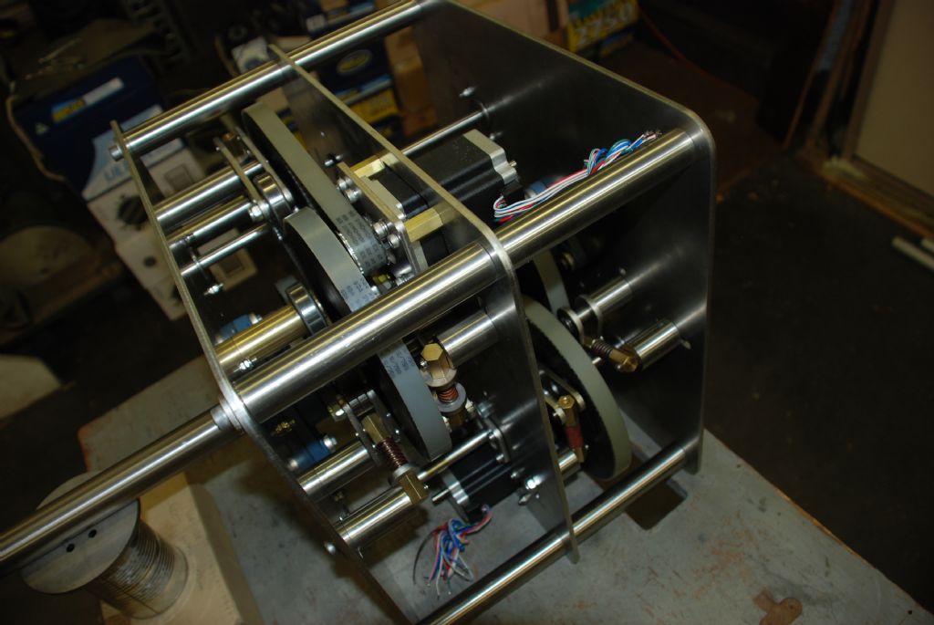
Tower clock with epoxy composite timing gears.

Advert

Tower clock with epoxy composite timing gears.

Home Forums Clocks and Scientific Instruments Tower clock with epoxy composite timing gears.

Viewing 25 posts - 1 through 25 (of 32 total)
  • Author
    Posts
  • #3663
    John McNamara
    Participant
      @johnmcnamara74883

      Step motor driven and linked to GPS time Universal time

      Advert
      #118778
      John McNamara
      Participant
        @johnmcnamara74883

        Hi All

        An electronics whiz mate and and I more on the mechanical side, designed and built this clock mechanism, the face is about 1.8 metres in diameter mounted a three of floors up. The face is not yet completed.

        The machanism was designed in Autocad 3D.

        The clock frame was made from laser cut stainless steel farmed out to a local contractor. Note the inserted circlip and groove type ball bearings supporting the idler shafts, and the larger universal ball bearings and housings for the main shafts, the fit was extremely good, better than .01mm. Very little cleaning up as received from the laser cutter.

        The rest of the mechanism was made from SS bar 25mm for the posts 20mm for the minute hand and 45mm for the hour hand. The minute hand runs on Oil-lite sintered Bronze bearings double sealed into the hour hand shaft to keep out the rain. The hands not yet fitted will be attached with stainless steel taper lock hubs. A little Brass and Nylon completes the materials list.

        The timing pulleys are made from cast epoxy as detailed re a prototype here (On the MEW forum): **LINK** a pleasing result. 

        The timing pulleys are tensioned by spring loaded ball bearing tensioners to reduce backlash and give a little in high wind.

        The mechanism uses two step motors to drive the hands separately. This was done to enable quick adjustment of the time rather than cycling through 24 hours. It also reduces the complexity and number of gears required. The time is set by extracting Universal time from the GPS system, it is re set nightly at midnight. The rest of the time the clock is driven by a battery backed up local time base. The electronics using an Arduino microprocessor (apart from the stepper drivers) remarkably sits on a tiny board less than 100mmm square, it has been test running for nearly a year and never misses a beat perfect time to the Milisecond or better.

        We are still working on the LED face display including lit hands hence the slip ring in the photos. In the end it will be quite a light show.

        More photos are in my album.

        Cheers

        John McNamara and Leo Solosy

        dsc_6135.jpg

        Edited By John McNamara on 08/05/2013 13:43:07

        #118789
        John McNamara
        Participant
          @johnmcnamara74883

          Hi All

          An electronics whiz mate and and I more on the mechanical side, designed and built this clock mechanism, the face is about 1.8 metres in diameter mounted a three of floors up. The face is not yet completed.

          The machanism was designed in Autocad 3D.

          The clock frame was made from laser cut stainless steel farmed out to a local contractor. Note the inserted circlip and groove type ball bearings supporting the idler shafts, and the larger universal ball bearings and housings for the main shafts, the fit was extremely good, better than .01mm. Very little cleaning up as received from the laser cutter.

          The rest of the mechanism was made from SS bar 25mm for the posts 20mm for the minute hand and 45mm for the hour hand. The minute hand runs on Oil-lite sintered Bronze bearings double sealed into the hour hand shaft to keep out the rain. The hands not yet fitted will be attached with stainless steel taper lock hubs. A little Brass and Nylon completes the materials list.

          The timing pulleys are made from cast epoxy as detailed re a prototype here (On the MEW forum): **LINK** a pleasing result. 

          The timing pulleys are tensioned by spring loaded ball bearing tensioners to reduce backlash and give a little in high wind.

          The mechanism uses two step motors to drive the hands separately. This was done to enable quick adjustment of the time rather than cycling through 24 hours. It also reduces the complexity and number of gears required. The time is set by extracting Universal time from the GPS system, it is re set nightly at midnight. The rest of the time the clock is driven by a battery backed up local time base. The electronics using an Arduino microprocessor (apart from the stepper drivers) remarkably sits on a tiny board less than 100mmm square, it has been test running for nearly a year and never misses a beat perfect time to the Milisecond or better.

          We are still working on the LED face display including lit hands hence the slip ring in the photos. In the end it will be quite a light show.

          More photos are in my album.

          Cheers

          John McNamara and Leo Solosy

          dsc_6135.jpg

          Edited By John McNamara on 08/05/2013 13:43:07

          #118825
          Michael Gilligan
          Participant
            @michaelgilligan61133

            John, and Leo

            Great work … Thanks for sharing.

            MichaelG.

            #118836
            Michael Gilligan
            Participant
              @michaelgilligan61133

              John, and Leo

              Great work … Thanks for sharing.

              MichaelG.

              #118859
              Sub Mandrel
              Participant
                @submandrel

                Nice to see something really different.

                Our administrator proudly showed me the new radio control clock she got cheap for our meeting room today. She asked if I coud reset it so it wasn't running an hour fast.

                I suggested the reason it was cheap may be that it is set to Central European Time.

                No it does not look easy to neatly open the case and move the hands!

                Neil

                #118876
                Sub Mandrel
                Participant
                  @submandrel

                  Nice to see something really different.

                  Our administrator proudly showed me the new radio control clock she got cheap for our meeting room today. She asked if I coud reset it so it wasn't running an hour fast.

                  I suggested the reason it was cheap may be that it is set to Central European Time.

                  No it does not look easy to neatly open the case and move the hands!

                  Neil

                  #118894
                  Sub Mandrel
                  Participant
                    @submandrel

                    Nice to see something really different.

                    Our administrator proudly showed me the new radio control clock she got cheap for our meeting room today. She asked if I coud reset it so it wasn't running an hour fast.

                    I suggested the reason it was cheap may be that it is set to Central European Time.

                    No it does not look easy to neatly open the case and move the hands!

                    Neil

                    #118874
                    Les Jones 1
                    Participant
                      @lesjones1

                      Hi Neil,
                      If it's the same as one I took apart the front (clear plastic) could be removed. If you look in from the back it will have plastic clips which are part of the front around the perimeter. These can be released with a small screwdriver. This is assuming it is constructed the same way as the one I had.

                      Les.

                      #118892
                      Les Jones 1
                      Participant
                        @lesjones1

                        Hi Neil,
                        If it's the same as one I took apart the front (clear plastic) could be removed. If you look in from the back it will have plastic clips which are part of the front around the perimeter. These can be released with a small screwdriver. This is assuming it is constructed the same way as the one I had.

                        Les.

                        #118912
                        Les Jones 1
                        Participant
                          @lesjones1

                          Hi Neil,
                          If it's the same as one I took apart the front (clear plastic) could be removed. If you look in from the back it will have plastic clips which are part of the front around the perimeter. These can be released with a small screwdriver. This is assuming it is constructed the same way as the one I had.

                          Les.

                          #118899
                          Ian P
                          Participant
                            @ianp

                            That looks really well designed and implemented. I have done several projects using laser and waterjet cut parts and its pleasing to be able to use the parts just as delivered, For some jobs no additional work at all is needed. Marking out and cutting large items repeatedly, to accurate dimensions would be hard work in say 3mm SS but these cutting machine maintain better than 0.1mm over the whole area.

                            What are 'inserted circlip and groove' type bearings? also I can see the 20mm pillars but where does the 45mm bar fit in on the hour hand, or should that be tube?

                            What does the (spring loaded?) ballrace on the arm do?

                            Ian P

                            #118918
                            Ian P
                            Participant
                              @ianp

                              That looks really well designed and implemented. I have done several projects using laser and waterjet cut parts and its pleasing to be able to use the parts just as delivered, For some jobs no additional work at all is needed. Marking out and cutting large items repeatedly, to accurate dimensions would be hard work in say 3mm SS but these cutting machine maintain better than 0.1mm over the whole area.

                              What are 'inserted circlip and groove' type bearings? also I can see the 20mm pillars but where does the 45mm bar fit in on the hour hand, or should that be tube?

                              What does the (spring loaded?) ballrace on the arm do?

                              Ian P

                              #118937
                              Ian P
                              Participant
                                @ianp

                                That looks really well designed and implemented. I have done several projects using laser and waterjet cut parts and its pleasing to be able to use the parts just as delivered, For some jobs no additional work at all is needed. Marking out and cutting large items repeatedly, to accurate dimensions would be hard work in say 3mm SS but these cutting machine maintain better than 0.1mm over the whole area.

                                What are 'inserted circlip and groove' type bearings? also I can see the 20mm pillars but where does the 45mm bar fit in on the hour hand, or should that be tube?

                                What does the (spring loaded?) ballrace on the arm do?

                                Ian P

                                #118986
                                John McNamara
                                Participant
                                  @johnmcnamara74883

                                  Hi Ian Hi All

                                  As shown in the following link: **LINK**

                                  Snap ring groove bearings have a stout snap ring, or circlip, fitted in an off center groove machined into the outer ring of the bearing, the ring projects about 2.5mm. When working with laser cutting easy to clamp in position by using the circlip as a mounting face. in the clock design more than adequate holding considering the forces involved, in fact a very strong mount the snap rings are quite heavy gauge.

                                  To mount them I simply place a hole at the bearing diameter surrounded by four bolt holes in the plate design then draw a small matching clamp plate again at bearing diameter surrounded by four matching holes and the job is done. When assembling they are just slipped in and once clamped are quite firm.

                                  OK this is not the ideal setup for a super precision machine, however in this application .01mm location accuracy for hole placement was more then adequate to locat the shaft. What I was looking for was low friction, long lasting lubrication and radial stiffness with limited axial stifness, they are simple deep groove ball bearings that always have a small amount of axial play. 

                                  When working with laser cutting you have to free your mind of the normal "Too much time and too hard to make make" constraints you place on a part design. You also have to rethink the design to use flat plates as much as possible, even if you have to stack them up it does not matter, the laser is so fast travelling at many metres per minute, it will do the entire job in a few minutes anyway. If possible it is less expensive to not use many thicknesses of material, thus minimising the number of setup charges from the laser cutter.

                                  Most small jobs like this clock simply attract the minimum charge anyway so dont worry about adding lots of complexity and many parts.

                                  Nearly all free 2D cad packages can output a DXF text file, and just about all can can draw polylines for the cut line. The laser cutter will convert the file to match their machine. Alternatively just give them an accurate drawing and they will draw it in cad for an extra charge. Most will be happy to check a file for you and advise you of any changes needed to work with their system. Some will email you a help sheet.

                                  The pillars in this clock are 25mm diameter drilled and tapped M8 at the ends, the pillars were turned down to 15mm diameter over 2mm creating a step at each end. The pillars are located in 15mm holes in the side plates on that step. they were screwed on a stud on the centre plate then the outer plates were fitted with M8 cap screws on laser cut 5mm washers. I did not want to rely on the M8 bolts for location this method is more accurate.

                                  The 45mm (Finished size) hour shaft is indeed tube about 1200 long. One of the more difficult parts to make, thick walled SS tube turned out to be hard to get and when I did get it it was a rough forged finish. And it was not very straight! Several frustrating hours were spent machining it. Ther are several steps and it had inserted bushings requiring press fit boring in both ends.

                                  The spring loaded ball race is used as a belt tensioner. once installed the clock will be left for long periods without maintenance, Hopefully the tensioners will take up any wear and keep the belts tight. it was also thought that it would reduce the any backlash that might show up in buffeting wind. The parts were in the main just added the the laser list. although the brass clevis / spring assembly did take a bit of time to make. The spring is a Die spring a lot stiffer than it looks.

                                  Cheers
                                  John

                                  Edited By John McNamara on 09/05/2013 02:16:52

                                  #119006
                                  John McNamara
                                  Participant
                                    @johnmcnamara74883

                                    Hi Ian Hi All

                                    As shown in the following link: **LINK**

                                    Snap ring groove bearings have a stout snap ring, or circlip, fitted in an off center groove machined into the outer ring of the bearing, the ring projects about 2.5mm. When working with laser cutting easy to clamp in position by using the circlip as a mounting face. in the clock design more than adequate holding considering the forces involved, in fact a very strong mount the snap rings are quite heavy gauge.

                                    To mount them I simply place a hole at the bearing diameter surrounded by four bolt holes in the plate design then draw a small matching clamp plate again at bearing diameter surrounded by four matching holes and the job is done. When assembling they are just slipped in and once clamped are quite firm.

                                    OK this is not the ideal setup for a super precision machine, however in this application .01mm location accuracy for hole placement was more then adequate to locat the shaft. What I was looking for was low friction, long lasting lubrication and radial stiffness with limited axial stifness, they are simple deep groove ball bearings that always have a small amount of axial play. 

                                    When working with laser cutting you have to free your mind of the normal "Too much time and too hard to make make" constraints you place on a part design. You also have to rethink the design to use flat plates as much as possible, even if you have to stack them up it does not matter, the laser is so fast travelling at many metres per minute, it will do the entire job in a few minutes anyway. If possible it is less expensive to not use many thicknesses of material, thus minimising the number of setup charges from the laser cutter.

                                    Most small jobs like this clock simply attract the minimum charge anyway so dont worry about adding lots of complexity and many parts.

                                    Nearly all free 2D cad packages can output a DXF text file, and just about all can can draw polylines for the cut line. The laser cutter will convert the file to match their machine. Alternatively just give them an accurate drawing and they will draw it in cad for an extra charge. Most will be happy to check a file for you and advise you of any changes needed to work with their system. Some will email you a help sheet.

                                    The pillars in this clock are 25mm diameter drilled and tapped M8 at the ends, the pillars were turned down to 15mm diameter over 2mm creating a step at each end. The pillars are located in 15mm holes in the side plates on that step. they were screwed on a stud on the centre plate then the outer plates were fitted with M8 cap screws on laser cut 5mm washers. I did not want to rely on the M8 bolts for location this method is more accurate.

                                    The 45mm (Finished size) hour shaft is indeed tube about 1200 long. One of the more difficult parts to make, thick walled SS tube turned out to be hard to get and when I did get it it was a rough forged finish. And it was not very straight! Several frustrating hours were spent machining it. Ther are several steps and it had inserted bushings requiring press fit boring in both ends.

                                    The spring loaded ball race is used as a belt tensioner. once installed the clock will be left for long periods without maintenance, Hopefully the tensioners will take up any wear and keep the belts tight. it was also thought that it would reduce the any backlash that might show up in buffeting wind. The parts were in the main just added the the laser list. although the brass clevis / spring assembly did take a bit of time to make. The spring is a Die spring a lot stiffer than it looks.

                                    Cheers
                                    John

                                    Edited By John McNamara on 09/05/2013 02:16:52

                                    #119024
                                    John McNamara
                                    Participant
                                      @johnmcnamara74883

                                      Hi Ian Hi All

                                      As shown in the following link: **LINK**

                                      Snap ring groove bearings have a stout snap ring, or circlip, fitted in an off center groove machined into the outer ring of the bearing, the ring projects about 2.5mm. When working with laser cutting easy to clamp in position by using the circlip as a mounting face. in the clock design more than adequate holding considering the forces involved, in fact a very strong mount the snap rings are quite heavy gauge.

                                      To mount them I simply place a hole at the bearing diameter surrounded by four bolt holes in the plate design then draw a small matching clamp plate again at bearing diameter surrounded by four matching holes and the job is done. When assembling they are just slipped in and once clamped are quite firm.

                                      OK this is not the ideal setup for a super precision machine, however in this application .01mm location accuracy for hole placement was more then adequate to locat the shaft. What I was looking for was low friction, long lasting lubrication and radial stiffness with limited axial stifness, they are simple deep groove ball bearings that always have a small amount of axial play. 

                                      When working with laser cutting you have to free your mind of the normal "Too much time and too hard to make make" constraints you place on a part design. You also have to rethink the design to use flat plates as much as possible, even if you have to stack them up it does not matter, the laser is so fast travelling at many metres per minute, it will do the entire job in a few minutes anyway. If possible it is less expensive to not use many thicknesses of material, thus minimising the number of setup charges from the laser cutter.

                                      Most small jobs like this clock simply attract the minimum charge anyway so dont worry about adding lots of complexity and many parts.

                                      Nearly all free 2D cad packages can output a DXF text file, and just about all can can draw polylines for the cut line. The laser cutter will convert the file to match their machine. Alternatively just give them an accurate drawing and they will draw it in cad for an extra charge. Most will be happy to check a file for you and advise you of any changes needed to work with their system. Some will email you a help sheet.

                                      The pillars in this clock are 25mm diameter drilled and tapped M8 at the ends, the pillars were turned down to 15mm diameter over 2mm creating a step at each end. The pillars are located in 15mm holes in the side plates on that step. they were screwed on a stud on the centre plate then the outer plates were fitted with M8 cap screws on laser cut 5mm washers. I did not want to rely on the M8 bolts for location this method is more accurate.

                                      The 45mm (Finished size) hour shaft is indeed tube about 1200 long. One of the more difficult parts to make, thick walled SS tube turned out to be hard to get and when I did get it it was a rough forged finish. And it was not very straight! Several frustrating hours were spent machining it. Ther are several steps and it had inserted bushings requiring press fit boring in both ends.

                                      The spring loaded ball race is used as a belt tensioner. once installed the clock will be left for long periods without maintenance, Hopefully the tensioners will take up any wear and keep the belts tight. it was also thought that it would reduce the any backlash that might show up in buffeting wind. The parts were in the main just added the the laser list. although the brass clevis / spring assembly did take a bit of time to make. The spring is a Die spring a lot stiffer than it looks.

                                      Cheers
                                      John

                                      Edited By John McNamara on 09/05/2013 02:16:52

                                      #119014
                                      magpie
                                      Participant
                                        @magpie

                                        Very nice work there John, can't wait to see the finished item in place.thumbs up Cheers Derek.

                                        #119030
                                        magpie
                                        Participant
                                          @magpie

                                          Very nice work there John, can't wait to see the finished item in place.thumbs up Cheers Derek.

                                          #119047
                                          magpie
                                          Participant
                                            @magpie

                                            Very nice work there John, can't wait to see the finished item in place.thumbs up Cheers Derek.

                                            #119048
                                            Peter Bell
                                            Participant
                                              @peterbell11509

                                              That looks a really good job John Absolutley facinating

                                              Would be interested to know more about and just wondered if you will be writing it up anywhere including the gps electronics?

                                              Just repairing a small trurret clock with a worn out dead beat escapement and made new pallet arms and nibs using my cnc mill. Never managed to make successful deadbeat pallets before so feeling quite pleased at the moment.

                                              Peter

                                              #119062
                                              Peter Bell
                                              Participant
                                                @peterbell11509

                                                That looks a really good job John Absolutley facinating

                                                Would be interested to know more about and just wondered if you will be writing it up anywhere including the gps electronics?

                                                Just repairing a small trurret clock with a worn out dead beat escapement and made new pallet arms and nibs using my cnc mill. Never managed to make successful deadbeat pallets before so feeling quite pleased at the moment.

                                                Peter

                                                #119083
                                                Peter Bell
                                                Participant
                                                  @peterbell11509

                                                  That looks a really good job John Absolutley facinating

                                                  Would be interested to know more about and just wondered if you will be writing it up anywhere including the gps electronics?

                                                  Just repairing a small trurret clock with a worn out dead beat escapement and made new pallet arms and nibs using my cnc mill. Never managed to make successful deadbeat pallets before so feeling quite pleased at the moment.

                                                  Peter

                                                  #119148
                                                  Ian P
                                                  Participant
                                                    @ianp

                                                    John

                                                    I love your clock, but have a few more questions.

                                                    Presumably there are flanges on the timing belt pinions as they don't show well on the picture. Are the belt tensioner rollers the full width of the back of the belt? In my experience once tensioned the belts do not slacken off, so were you concerned about the composite pulleys wearing?

                                                    I have not used the grooved ballraces before but I have used flanged races to do the same job as the ones in your clock.

                                                    0.01mm accuracy is probably far higher precision than you need for a belt driven clock but it come free with laser cutting, the best thing is that the accuracy is maintained over large distances so errors are not usually cumulative.

                                                    Ian P

                                                    #119162
                                                    Ian P
                                                    Participant
                                                      @ianp

                                                      John

                                                      I love your clock, but have a few more questions.

                                                      Presumably there are flanges on the timing belt pinions as they don't show well on the picture. Are the belt tensioner rollers the full width of the back of the belt? In my experience once tensioned the belts do not slacken off, so were you concerned about the composite pulleys wearing?

                                                      I have not used the grooved ballraces before but I have used flanged races to do the same job as the ones in your clock.

                                                      0.01mm accuracy is probably far higher precision than you need for a belt driven clock but it come free with laser cutting, the best thing is that the accuracy is maintained over large distances so errors are not usually cumulative.

                                                      Ian P

                                                    Viewing 25 posts - 1 through 25 (of 32 total)
                                                    • Please log in to reply to this topic. Registering is free and easy using the links on the menu at the top of this page.

                                                    Advert

                                                    Latest Replies

                                                    Viewing 25 topics - 1 through 25 (of 25 total)
                                                    Viewing 25 topics - 1 through 25 (of 25 total)

                                                    View full reply list.

                                                    Advert

                                                    Newsletter Sign-up