Amateurish Engine

Advert

Amateurish Engine

Home Forums Stationary engines Amateurish Engine

Viewing 23 posts - 1 through 23 (of 23 total)
  • Author
    Posts
  • #646880
    JasonB
    Moderator
      @jasonb

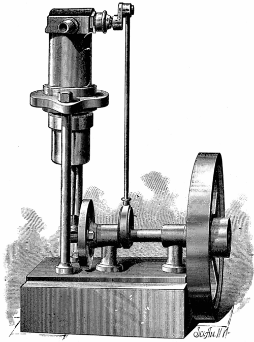
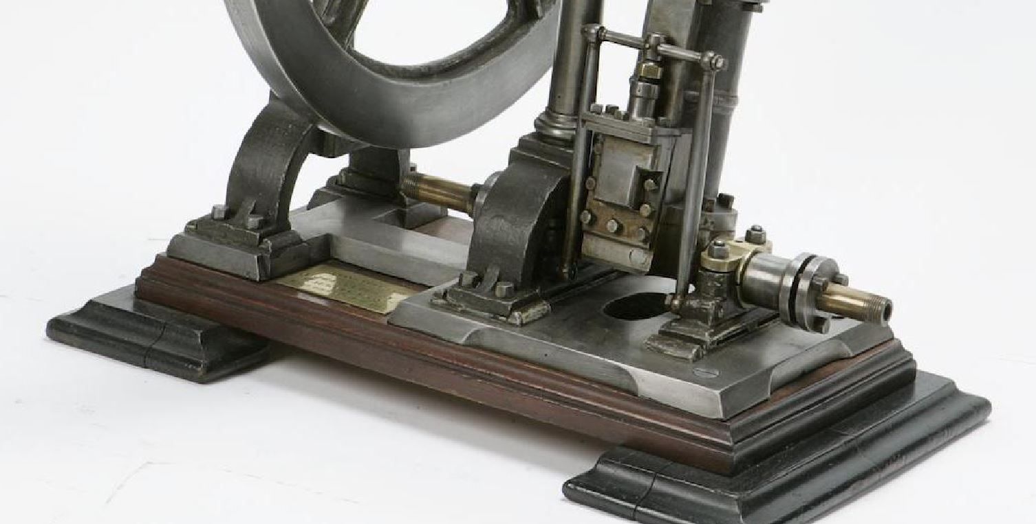
      I think I first saw the image below of this engine when it came up on Pintrest and it caught my eye. A bit more digging about with Google showed that it originated from the 1905 edition of "Scientific American" and was listed under Amateur Mechanics as a "Simple Single-Acting Steam Engine"

      I manages to find another engraving that showed an end view and side view sectioned through the cylinder with a couple of other details of the valve but that was too grainy to be of much use. There was also a basic description of the engine and some key sizes. One feature was the use of brass tubes for the cylinder and piston that would telescope together thus saving having to bore the cylinder and machine a piston on a treadle lathe that it was assumed most amateurs at the time would have.

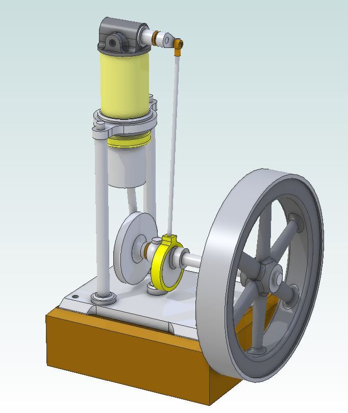
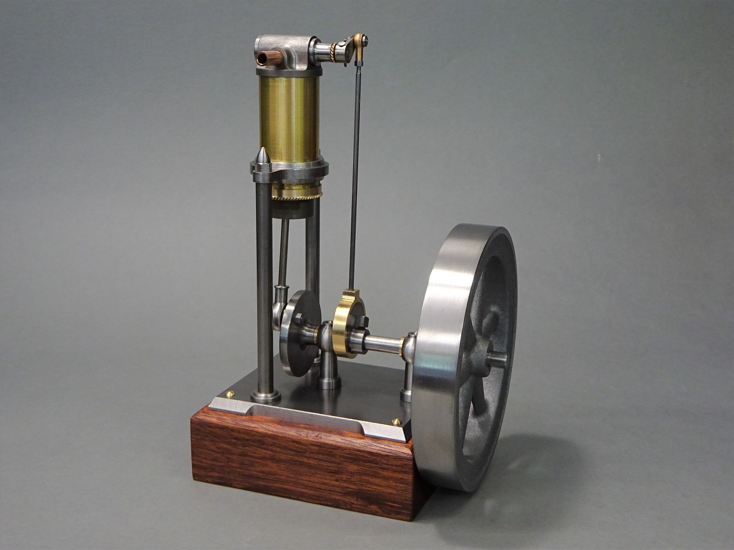
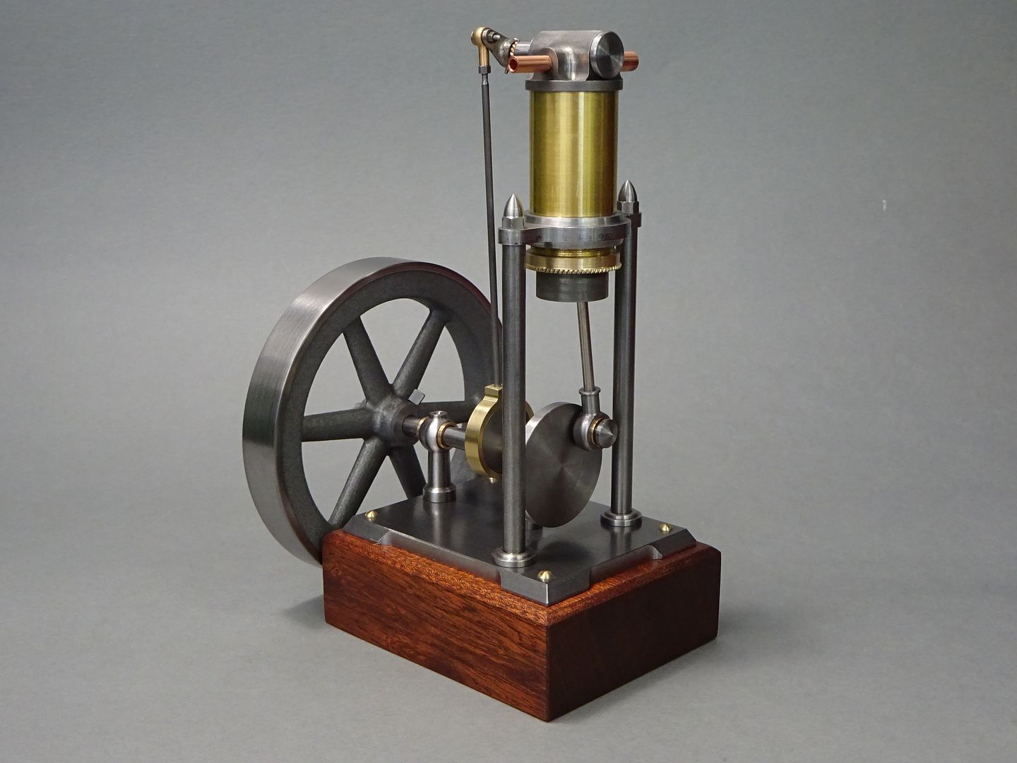
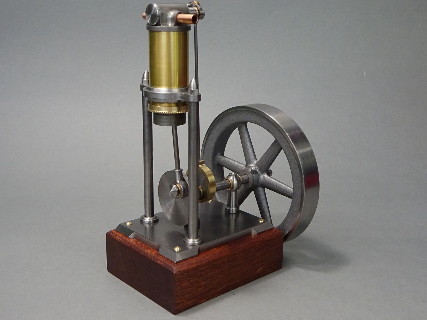
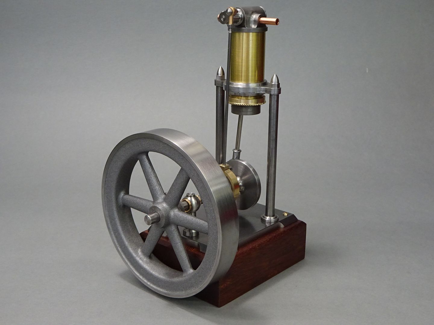
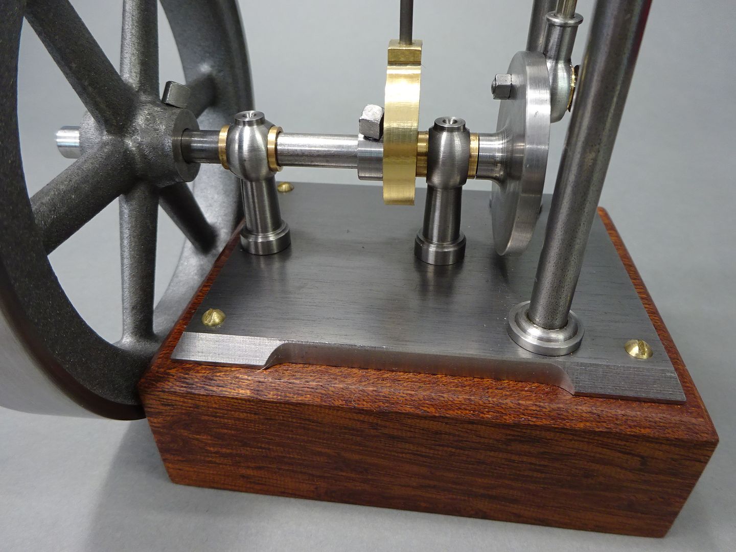
      It was said to be approx 1/20 HP and had a bore of 1.5" x stroke of 2" and an 8" flywheel. I set about drawing it up to suit some thick wall brass tube that I had for the cylinder and that dictated that I use a 19mm bore so my metric design is about half size. I also altered some of the construction methods suggested and also added a bit more elaborate detail so that I would not make it too quickly.

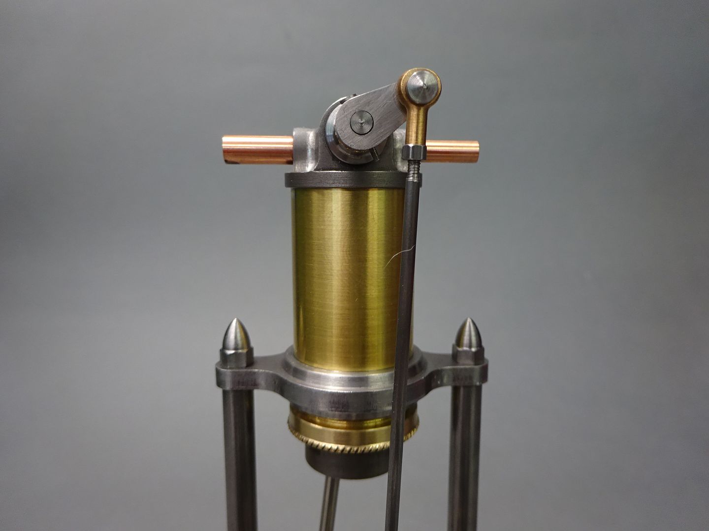
      For example the text suggests that the plate supporting the cylinder be sandwiched between two threaded rings with the threads being hand chased and the assembly then being soft soldered together. I opted to make the plate and the two rings as one then fix to the cylinder with Loctite. Strangely it suggests the cylinder head is a casting with what looked like cored passages, I opted for an inserted sleeve to form the ports for the rocking valve's spindle to rotate in. Rather than brass on brass I went for a piston machined from steel.

      Edited By JasonB on 29/05/2023 17:00:35

      Advert
      #3543
      JasonB
      Moderator
        @jasonb
        #646930
        Nigel Graham 2
        Participant
          @nigelgraham2

          Interesting engine!

          I wonder if it was based on a full-size one by some manufacturer perhaps no longer trading even before Scientific American published the model design.

          #646940
          JasonB
          Moderator
            @jasonb

            It was not published as a "Model" they say it would be capable of powering the treadle lathe it was built on or 2-3 sewing machines. Although the terms are more often used for IC engines I would class it as a "small power" or Fractional Horsepower" workshop engine.

            #646942
            not done it yet
            Participant
              @notdoneityet

              JB,

              Did you reduce other dimensions – other than the bore? If you halved the bore it will be only one quarter (not half) of the capacity, surely?

              #646943
              JasonB
              Moderator
                @jasonb
                Posted by not done it yet on 30/05/2023 07:17:01:

                JB,

                Did you reduce other dimensions – other than the bore? If you halved the bore it will be only one quarter (not half) of the capacity, surely?

                Yes all reduced by approx 50% so everything is half size, 25mm stroke from original 2" and 99mm flywheel dia from original 8" dia (100mm stock hence 99mm finish)

                Capacity is actually 1/8th of the original 0.5 x 0.5 x 0.5

                Edited By JasonB on 30/05/2023 07:40:14

                #646953
                Phil Whitley
                Participant
                  @philwhitley94135

                  This ICE design seems to use the same induction/exhause valve system.

                  Phil

                  #646966
                  JasonB
                  Moderator
                    @jasonb

                    That looks more like what you tend to find on a lot of front induction model aero engines where the incoming air/fuel mix is drawn in via a hollow crankshaft.

                    Firefly157

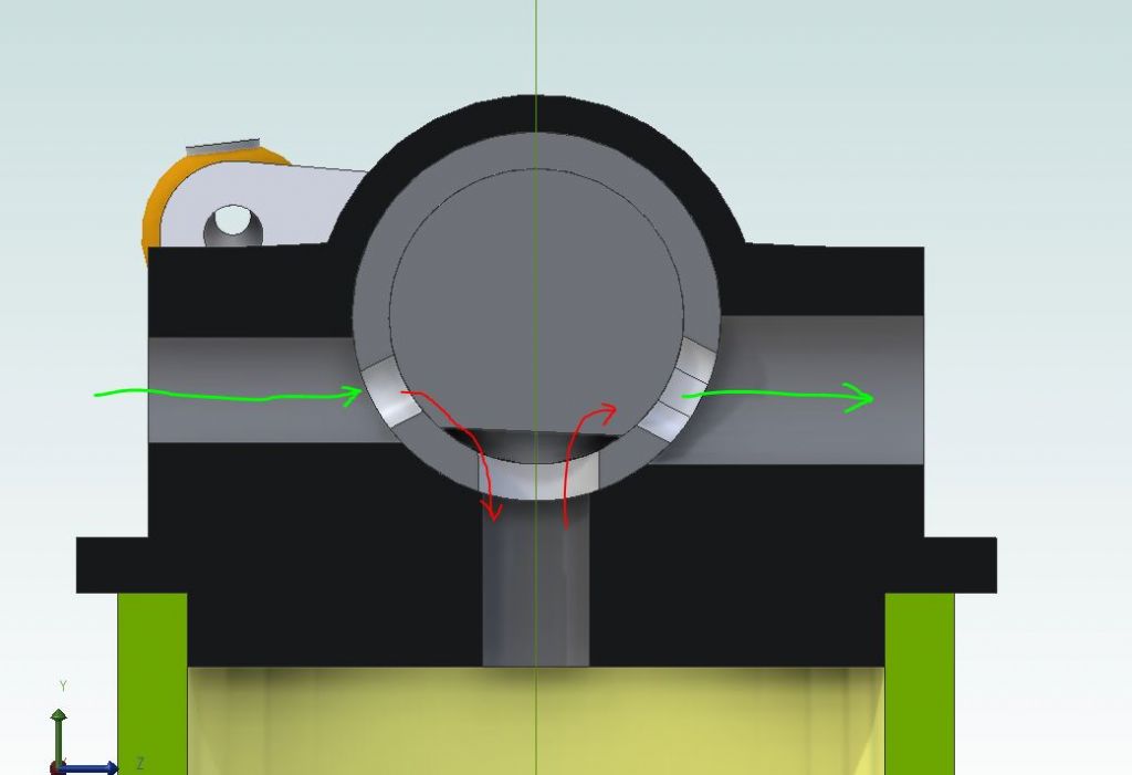
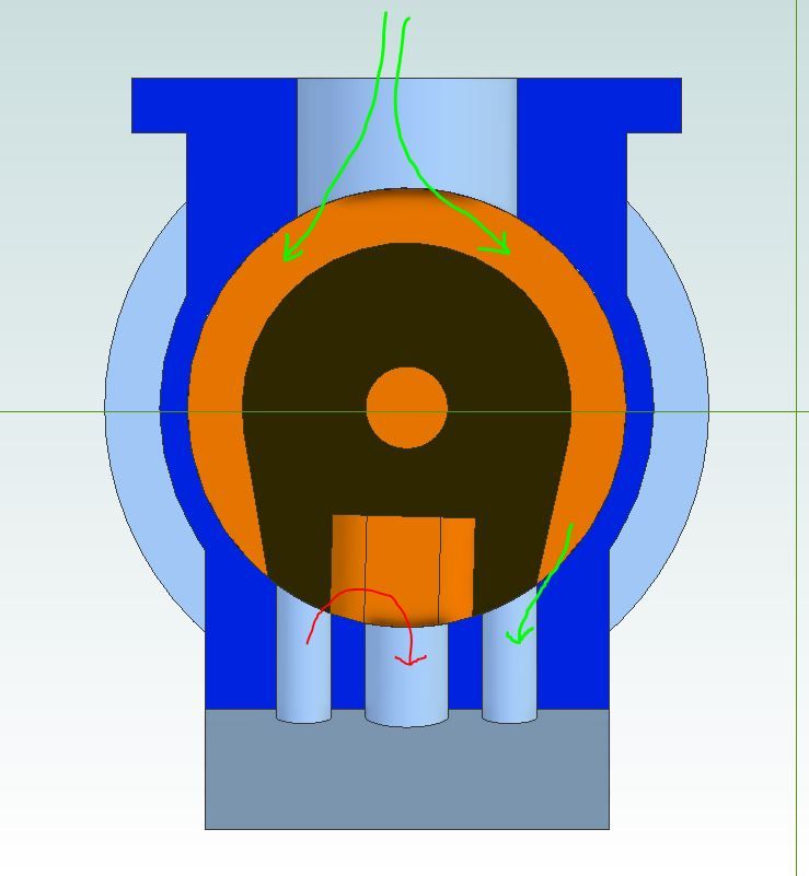
                    The rocking valve is really nothing more than a diverter valve or can be thought of like a common steam engine slide valve except the port face is curved not flat. This is the one for this single acting engine as the valve spindle with a simple flat machined on it rocks it opens the inlet and then the exhaust and so on

                    am valve.jpg

                    Things get a bit more complex on a double acting engine, this is the one from my Filer and Stowell where the incoming air/steam passes around the valve much like filling a traditional valve chest and then as the valve rotates one side is open to the incoming while at the same time the cavity in the valve links the other end to the central exhaust

                    fns valve.jpg

                    #646968
                    Hopper
                    Participant
                      @hopper

                      A rotary sleeve valve like that was tried on various motorcycles back in the 1920s but they could never maintain a good seal once the rotary sleeve and its housing in the cylinder head wore a bit. And being subject to hot corrosive exhaust gasses, wear was rapid.

                      The rocking valve on the old steam engine in the OP is more reminiscent of a Corliss type valve gear. Pretty neat to watch in action.

                      #646970
                      JasonB
                      Moderator
                        @jasonb

                        That's it Hopper just like a corliss valve except it has two ports to open/close rather than one.

                        The makers of that Filer and Stowell were better known for their corliss engines but did the less complex/expensive rocking valve ones where economy was not much of an issue hence they were often found in saw mills that had a good supply of waste wood to fire the boilers

                        #647040
                        JasonB
                        Moderator
                          @jasonb

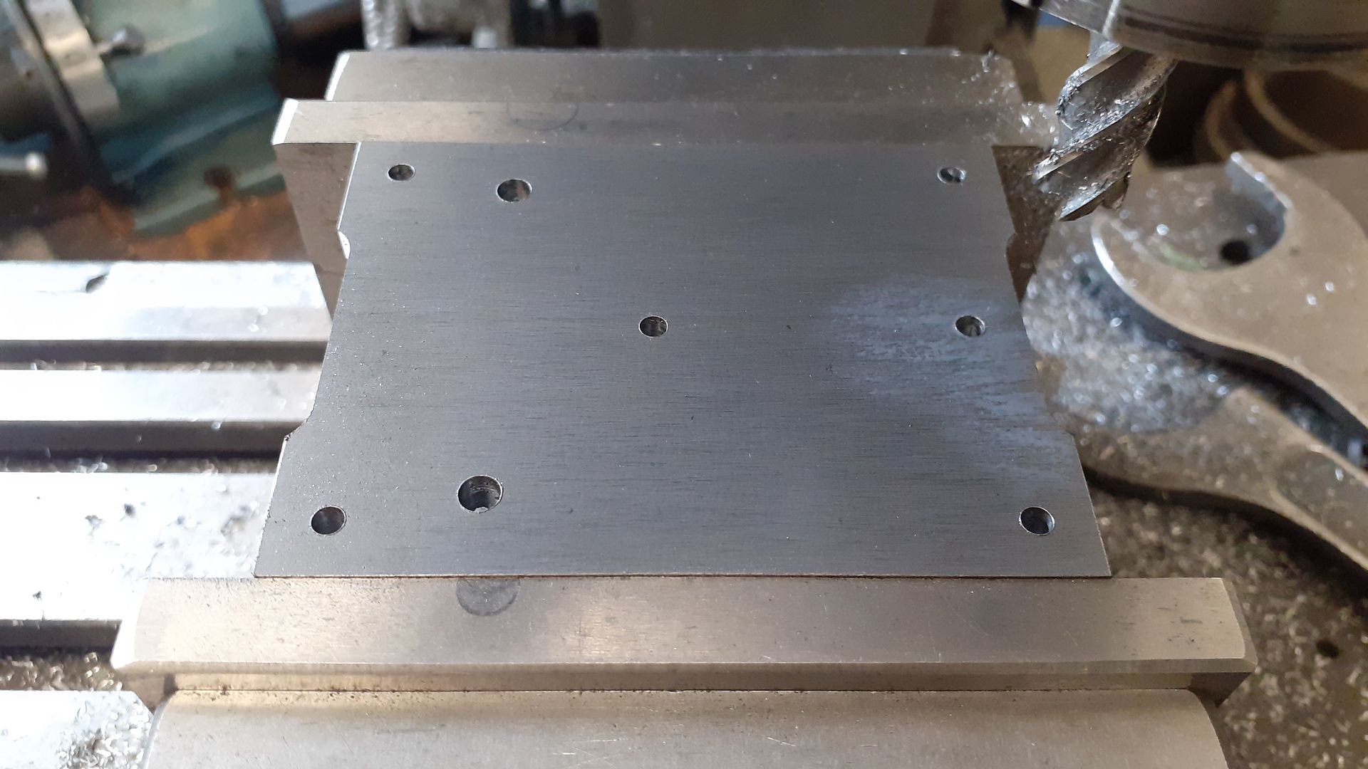
                          As I mentioned in the opening post I wanted to add a bit more detail and ornamentation and the rather plain flat plate of the original engines base was the first candidate for that. I have had a couple of images of this engine in my "future projects" file and likes the edge detail it featured.

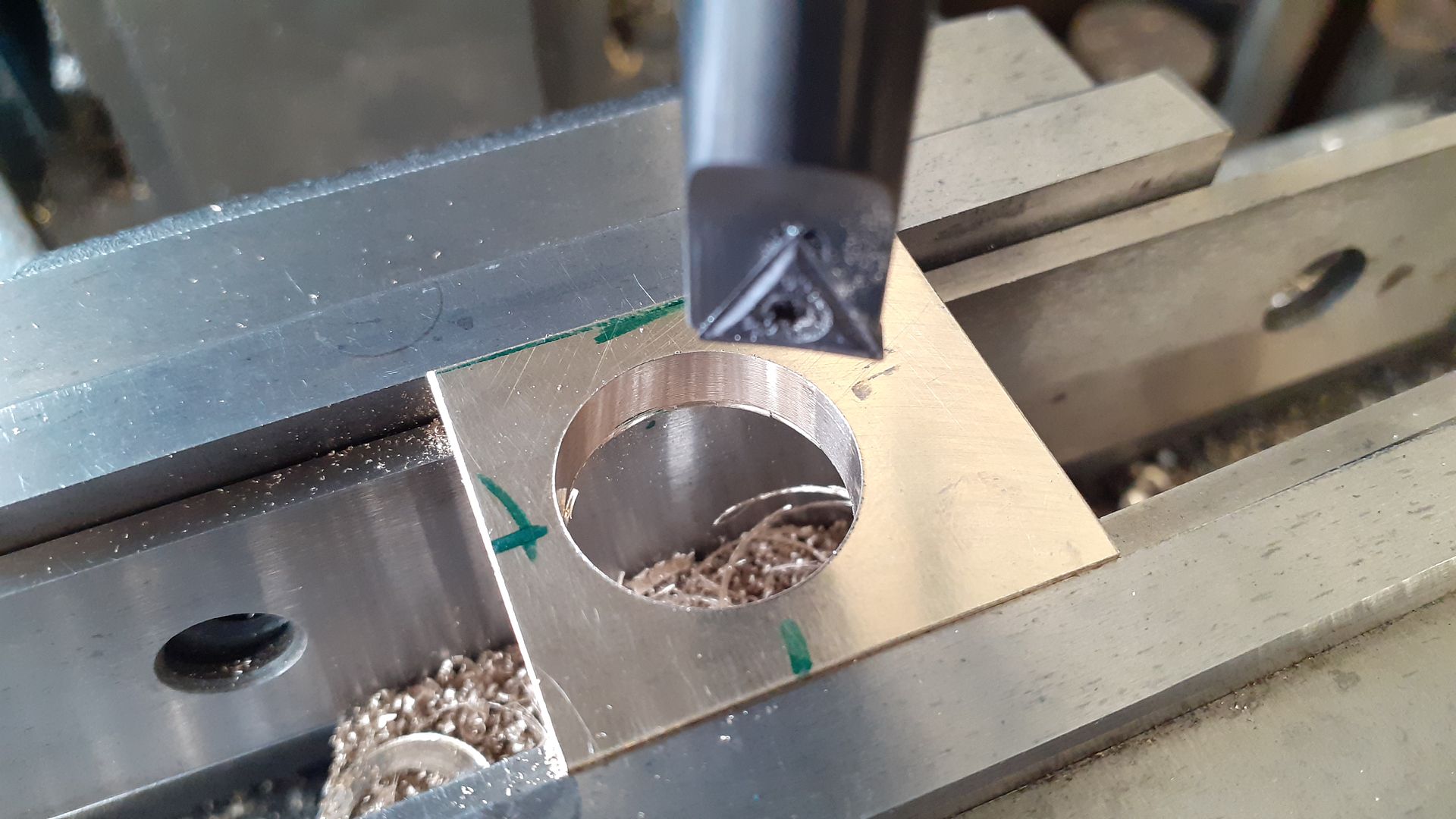
                          So after milling some 5mm plate down to size and drilling the various holes I started by using a 10mm cutter to do the recesses along the edges

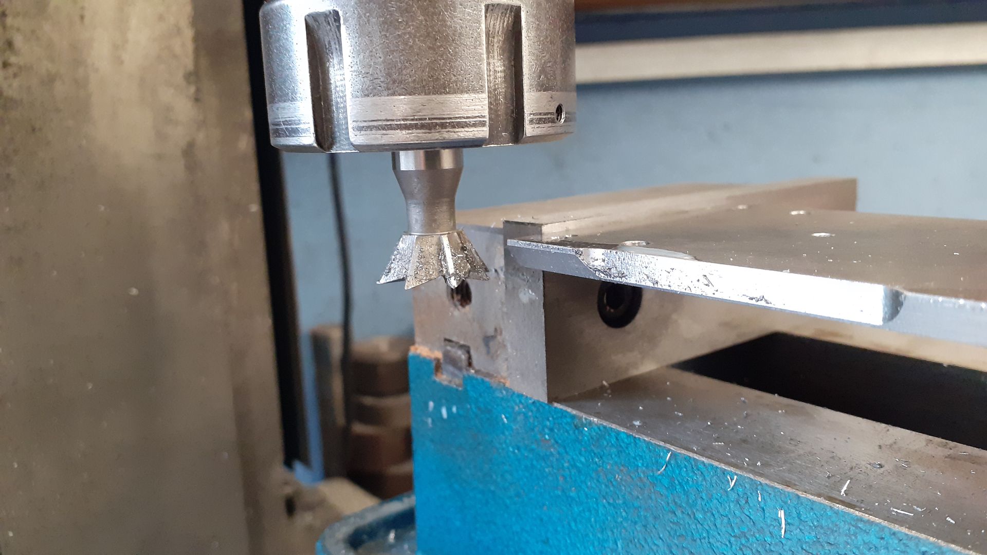
                          After that the plate was held upside down and a dovetail cutter used to chamfer the edges to a height of 4mm which left a small 1mm vertical edge around what would be the bottom.

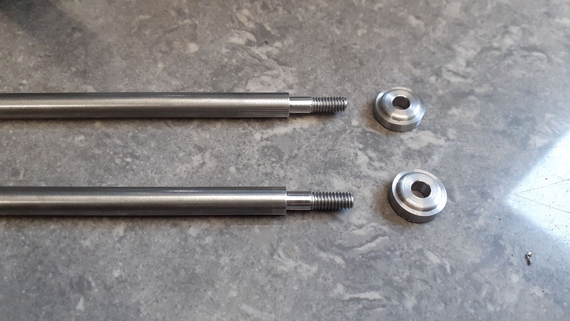
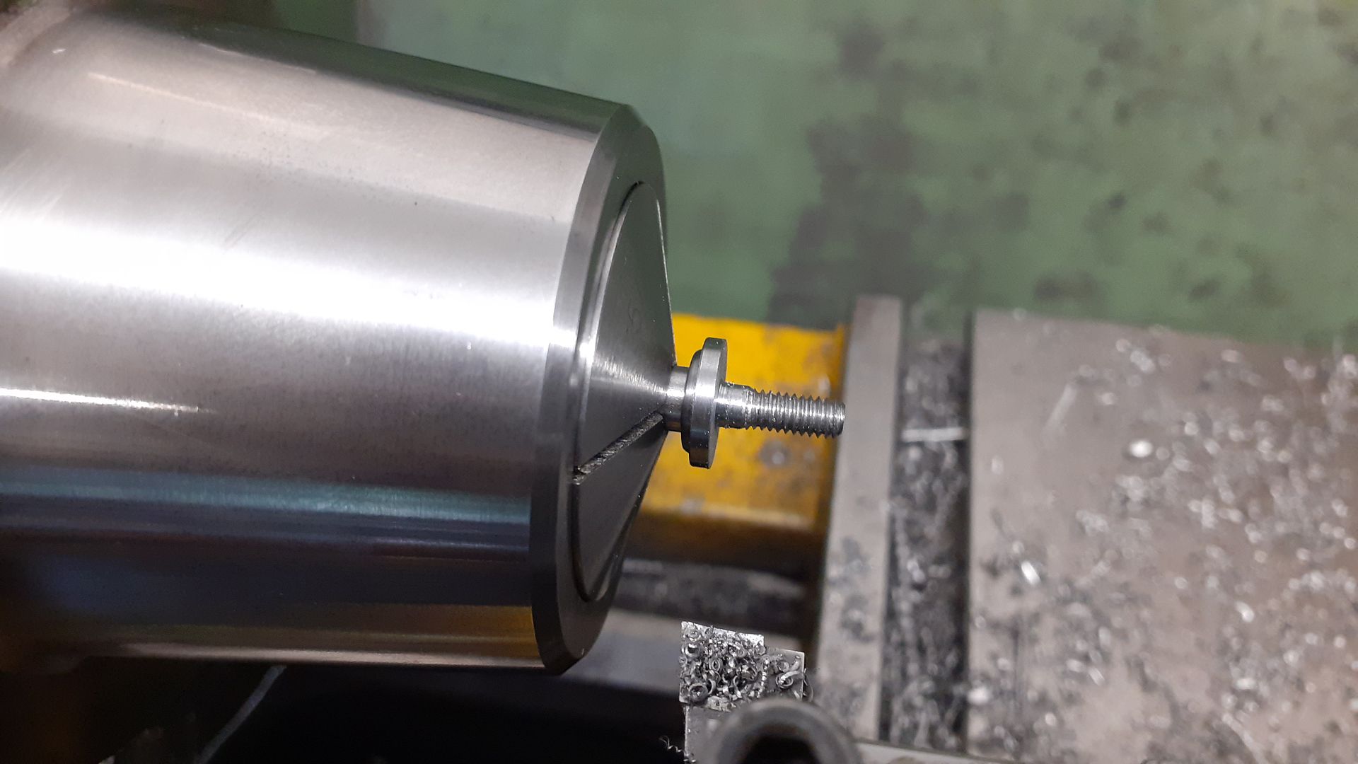
                          I deliberated for some time on whether to stick with parallel columns or to taper them, in the end straight won so it was just a case of turning spigots on each end that were threaded M4. Two bases were turned with a bit more decoration to the profile and then parted off over length.

                          The feet were attached to the longer bottom spigots with Loctite and once set were faced back to give the finished length from underside of base to the shoulder at the top of column

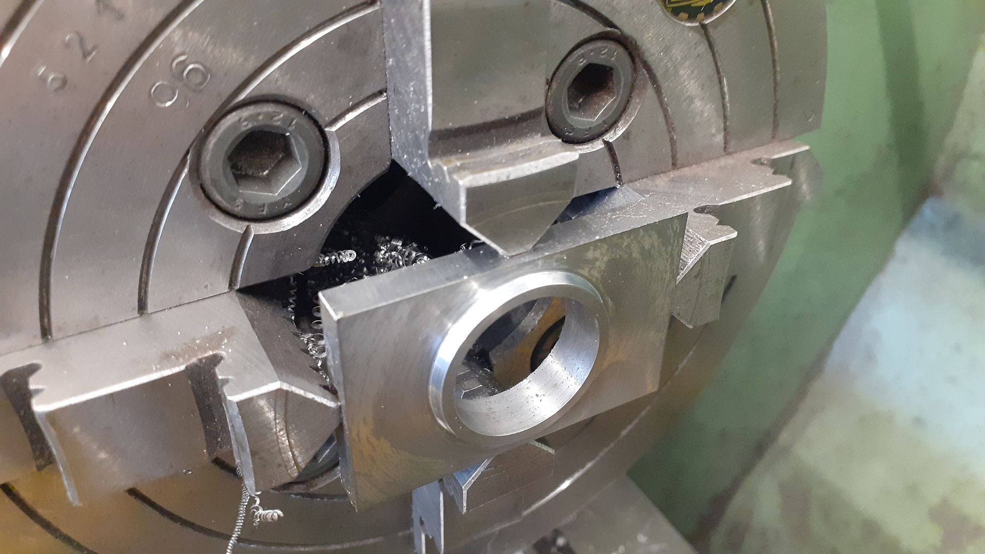
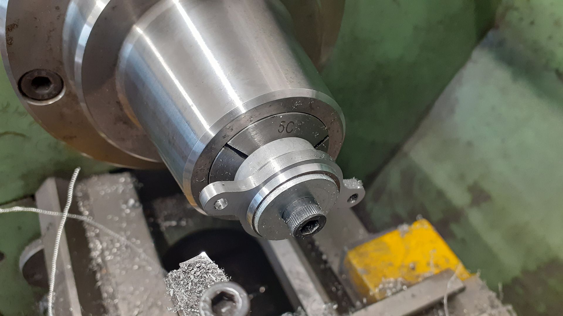
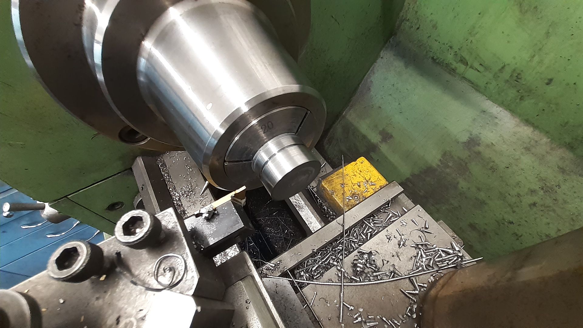
                          For the cylinder support a piece of 8mm flat bar was held in the 4-jaw and bored to 22mm then the integral upper collar formed by turning 2mm off the face of the bar.

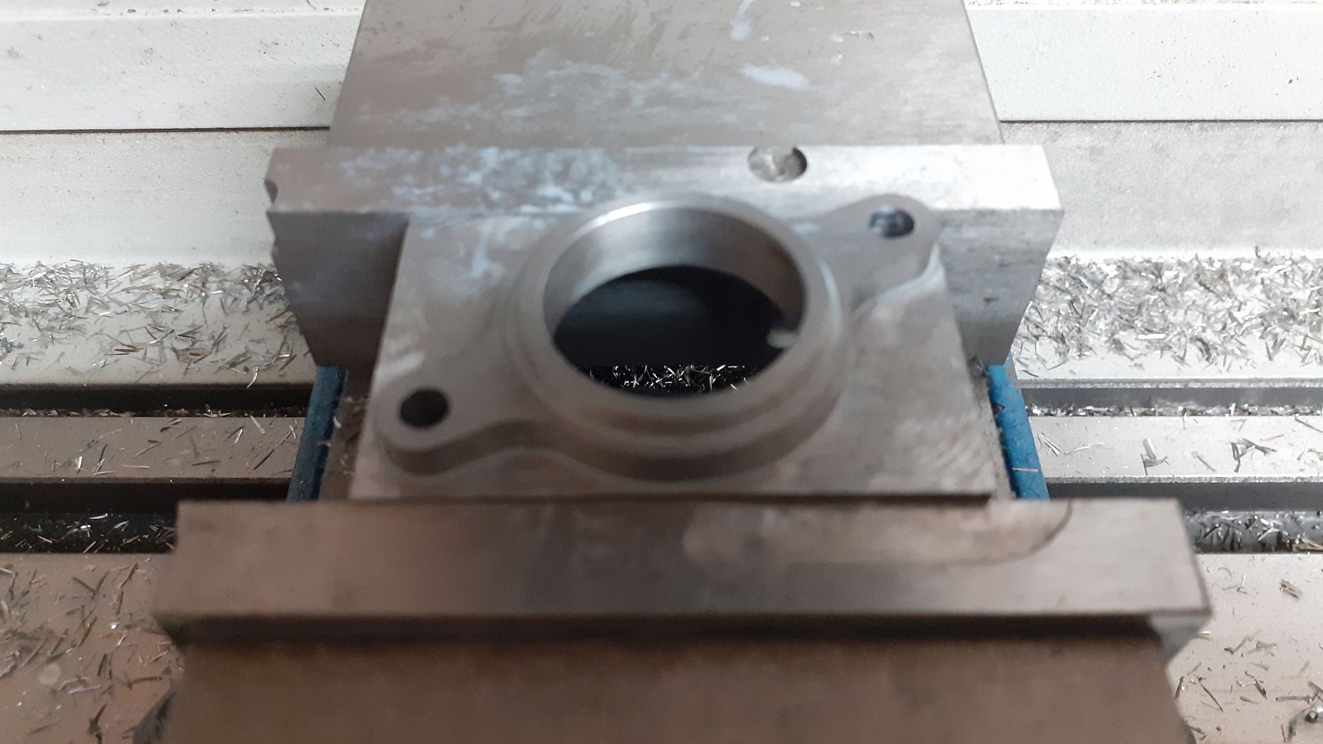
                          I took the option to profile and drill the two holes on the CNC but it could also be done easily enough with a rotary table. .

                          An old arbor was reused to hold the work while the thickness was reduced to 4mm leaving just the lower collar standing proud by 2mm.

                          Edited By JasonB on 30/05/2023 18:33:23

                          #647140
                          Tim Stevens
                          Participant
                            @timstevens64731

                            The date of this engine puts it bang in the middle of a period of history when there was a huge demand from all sorts of people for a small source of power. Sewing machines are mentioned, but there were also printers, dairies, bookbinders, etc, all needing power but not all the time (which is what steam was good for) The electric motor was going to solve their problems, but they had to wait for national distribution systems. Simple engines like this could help, but tended to involve fire risks, so were difficult to insure.

                            Cheers, Tim

                            #647248
                            JasonB
                            Moderator
                              @jasonb

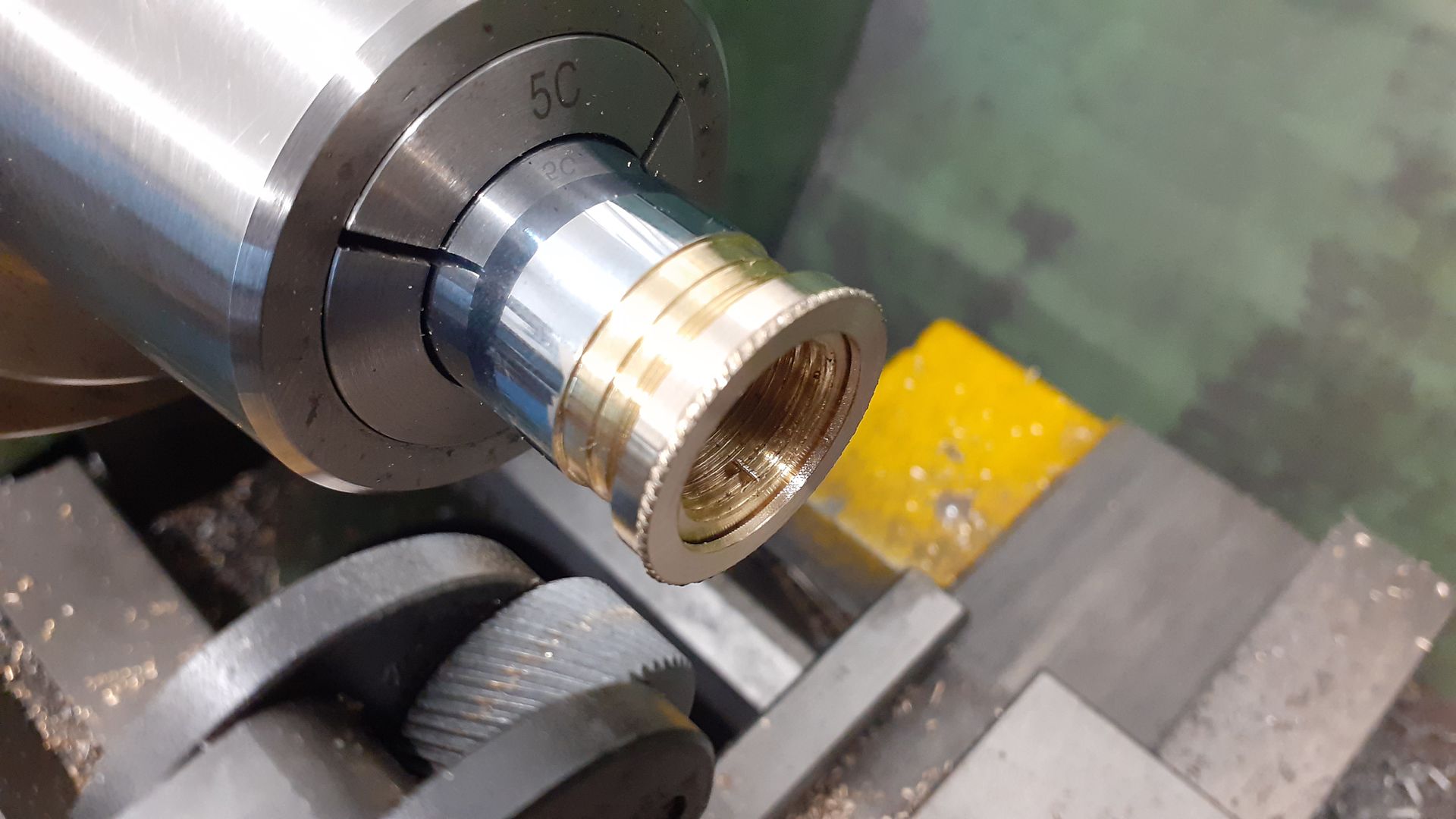
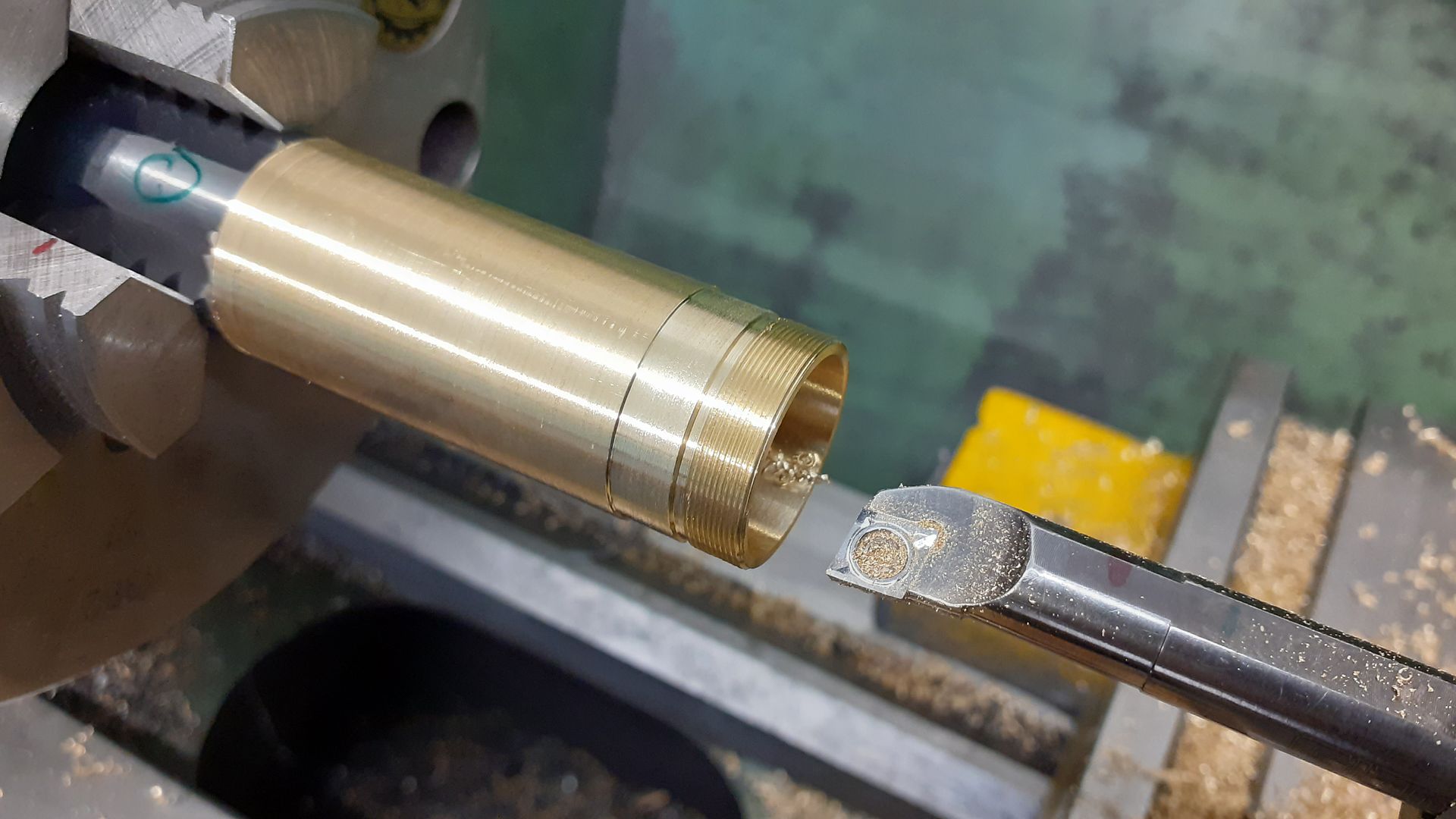
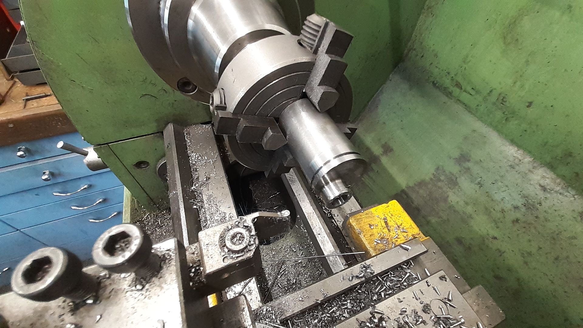
                              The piece of thick wall brass tube that I had came out at 22.7mm by the time the chrome plating had been skimmed off so I opted to use a M22 x 0.5mm thread for the gland nut that seals the end of the piston (no rings). I opted to make the female thread first and rather than single point cut it I took the opertunity to have ago a thread milling on the CNC. So an odd bar end of 1" brass was held in a 3-jaw chuck, the end milled flat and then the threading size and smaller clearance hole were bored with the CNC followed by thread milling.

                              With the internals done I cut a test make thread on the opposite end of the stock and screwed the gland nut onto that to do the remaining turning, the final operation was to use one wheel of a diamond knurl to add a rope type knurl to a half round bead that had previously been turned.

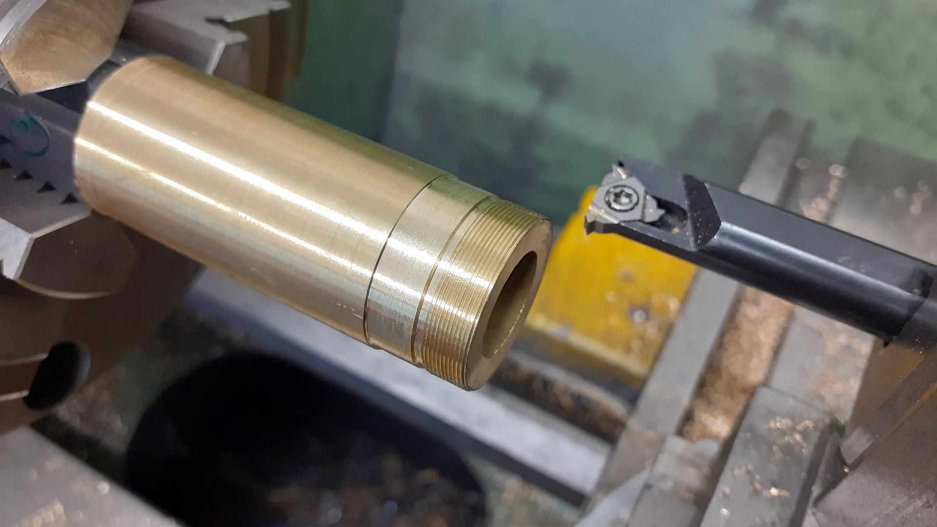
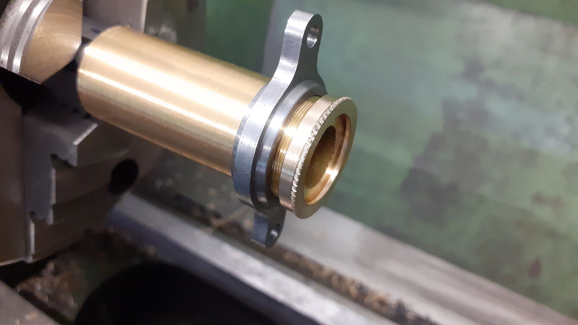
                              With sufficient length sticking out of the chuck the chrome was turned off the other end of the tube and then a 12mm length reduced to 22mm dia which gave a shallow shoulder to locate against the cylinder support plate. Following that the thread was cut, I find it easier to run the lathe backwards and bring the tool in from the far side, that way I can cut at several hundred rpm and not have to worry about overrunning the length of thread if I don't stop the lathe when required

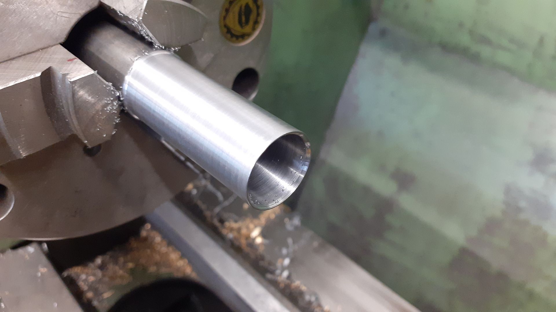
                              After checking the fit of the thread using the gland nut as a gauge I bored out the tube to the desired 19mm diameter. It was then sawn off and the top faced back to final length.

                              A piece of 20mm leaded steel was turned to fit the cylinder and then bored out to 17mm to leave a 1mm wall thickness, sawn off, faced to length and a 3mm hole put into the top ready to receive the small end yoke.

                              #647263
                              duncan webster 1
                              Participant
                                @duncanwebster1

                                We once employed a contract draughtsman who had worked on rotary valve IC engines based in the Bolton area. Frank Aspin? He reckoned that when they got the oil consumption down to less than the petrol consumption they thought they were making progress. Unfortunately he was only with us for a few weeks, he probably found something more interesting.

                                Edited By duncan webster on 01/06/2023 23:07:24

                                #647280
                                Rod Renshaw
                                Participant
                                  @rodrenshaw28584

                                  The late LBSC used to mention "Treblet " tube in some of his writings. This was a type of brass tube which he thought had been passed through dies 3 times to give a better than usual and more accurate finish, both inside and out. He mentions using it for boiler feed pump barrels and steam whistles, and says that one size fitted nicely inside the next size up. I wonder if this was the type of tube used for the original engine design.

                                  Rod

                                  #647284
                                  Dave Wootton
                                  Participant
                                    @davewootton

                                    Duncan's post on rotary valve IC engines and the name Frank Aspin bought back memories from a book " some unusual engines" by L.K.J Setright borrowed from the library years ago. Google search found a really interesting website on Aspin and his engines, lost part of this morning on there! Must have been an interesting character to meet.

                                    Very nice work again Jason on another interesting engine, always a pleasure to read.

                                    Dave

                                    Edited By Dave Wootton on 02/06/2023 11:53:45

                                    #647397
                                    JasonB
                                    Moderator
                                      @jasonb

                                      Rod, the short notes in the original article do mention "mandrel drawn" brass tube so sounds like something similar.

                                      At this stage I was enjoying the building so much that I did not take as many photos as I could have done but there is nothing too special about most of the remaining parts.

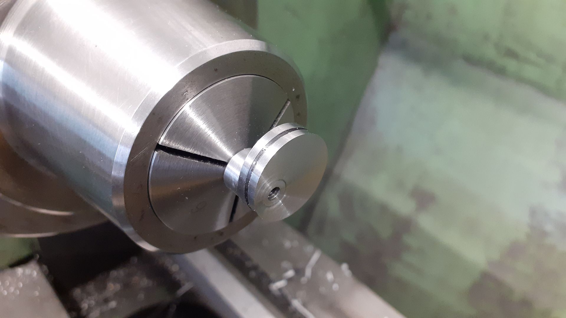
                                      The crank disc was roughed out and then a RCGT 06 button insert used to finish the back edge and give a nice large fillet to the protruding boss and then the hole was spotted, drilled 5.8mm with a stub drill and reamed 6mm before sawing the disc off of the piece of steel bar. It was then Loctited onto a length of 6mm precision ground mild steel and once that had gone off the front face was turned to final thickness thus ensuring the face was perpendicular to the shafts axis.

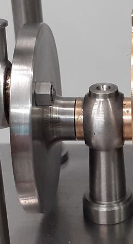
                                      The bearing supports that can also be seen in the photo above were turned from 12mm leaded steel using a ball turner to form the top and a 1mm radius tool to turn the tapered column so it blended in nicely to the ball. Moving over to the mill 3mm was taken off opposite faces and an 8mm hole drilled and reamed through to take the bearing. Back into the lathe a parting tool was used to form a 3mm dia spigot that could be threaded once cut off for a nut to hold the support to the base

                                      Bearings were simple turning and reaming from Colphos and loctited into place after which the oil hole was drilled through

                                      After turning the OD of the eccentric a 1mm parting insert was used to cut a central groove to retain the strap

                                      After which the stock was held in the small 4-jaw and clocked to give the desired throw before turning the spigot, spotting, drilling, reaming and then cut off

                                      After tapping for a M3 grub screw the eccentric was mounted on a 6mm bar so the sawn face could be turned back to the final 5mm thickness

                                      A piece of brass was square dup and then milled to 5mm thickness before boring to size using the eccentric to gauge the fit.

                                      The outside profile was done on the CNC but could quite easily be done on a rotary table or even with filing buttons depending on what you have available.

                                      The eccentric rad was just 2mm dia steel threaded at both ends and the end that screws into the strap had a small spigot turned to locate in the groove of the eccentric

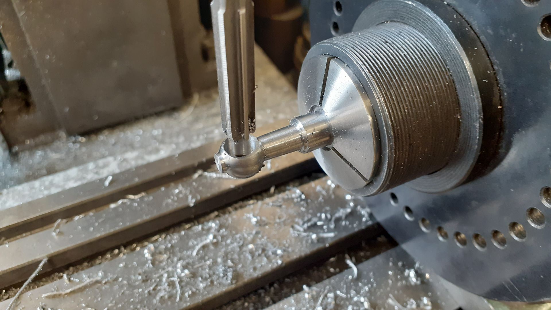
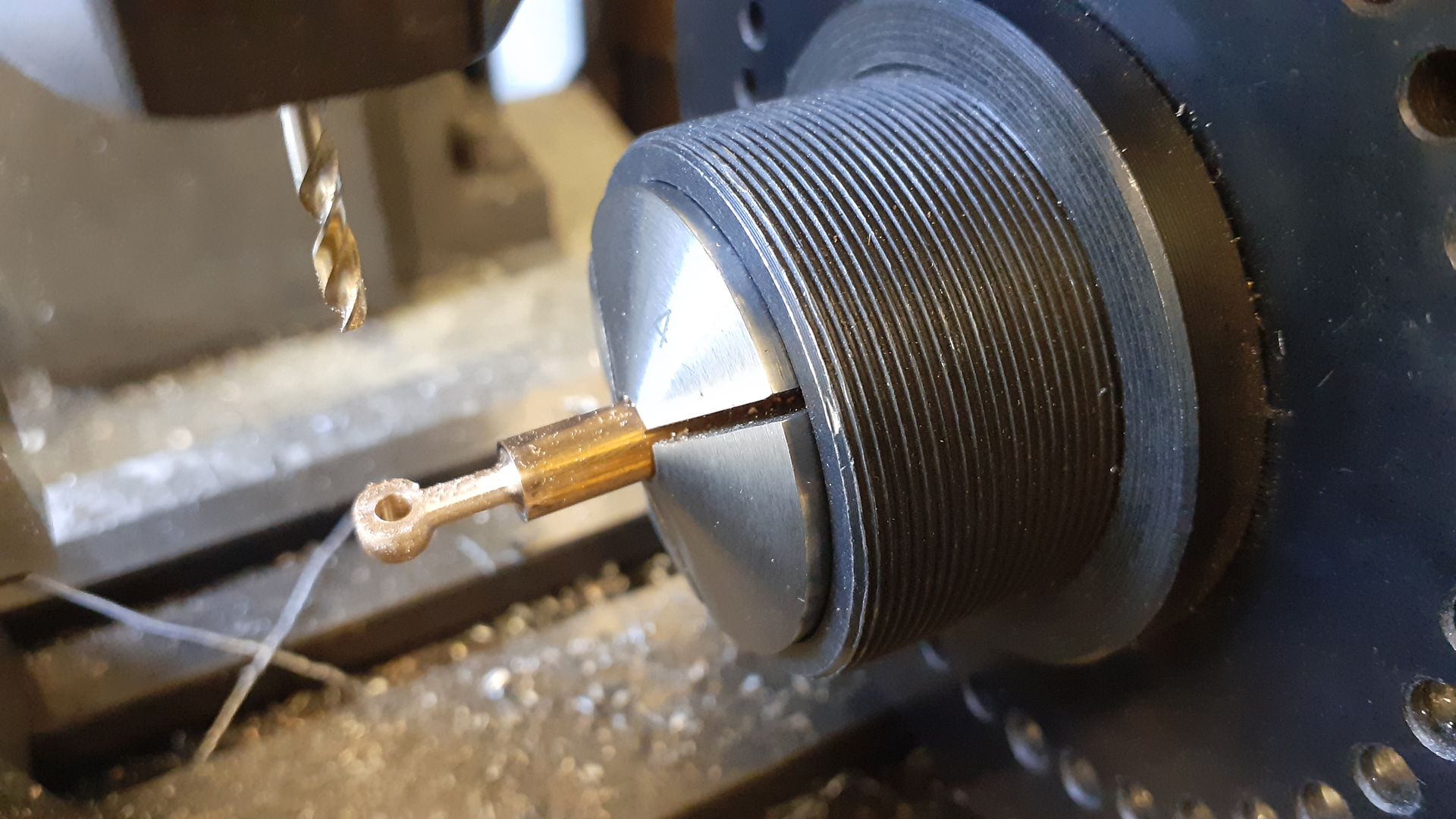
                                      For the top end of the rod I kept the ball shaped theme going when making the rod eye.

                                      #647575
                                      JasonB
                                      Moderator
                                        @jasonb

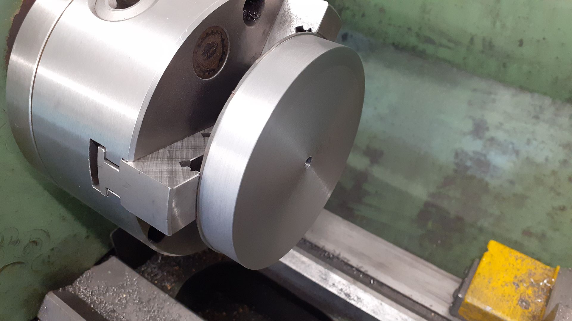
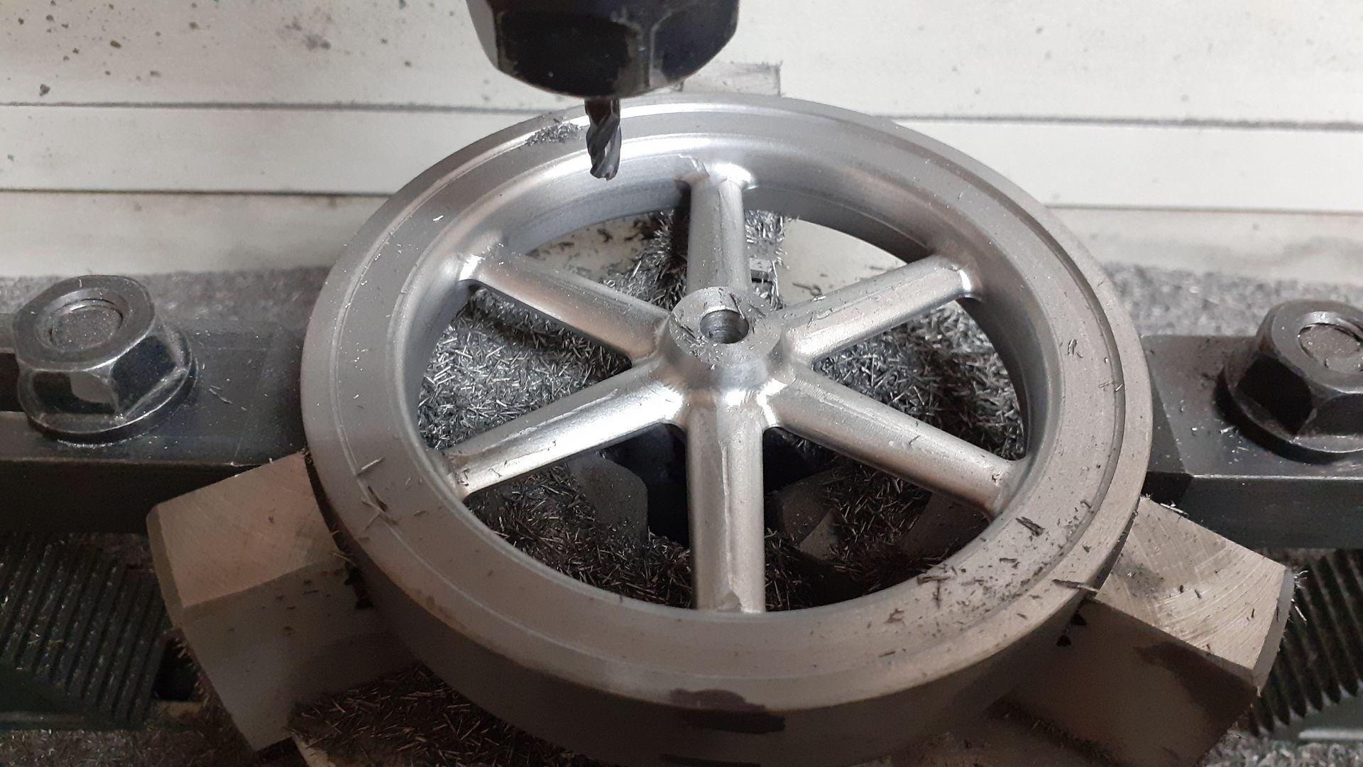
                                        The engraving shows a flywheel with a fairly deep section rim which no doubt helps get the single acting piston back up to TDC, most castings of the right size seemed a bit lacking in mass so I drew one up and set about making it from a slice of cast iron bar that I had to hand which required holding by the minimal amount while some gentle cuts were taken to clean it up.
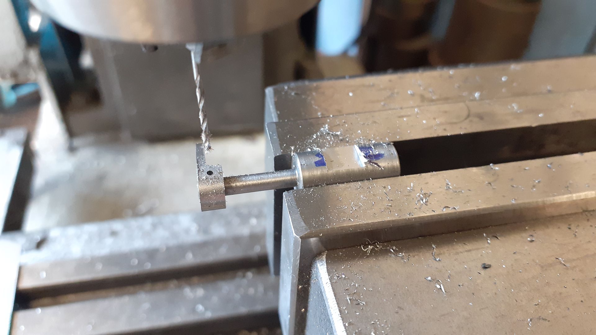
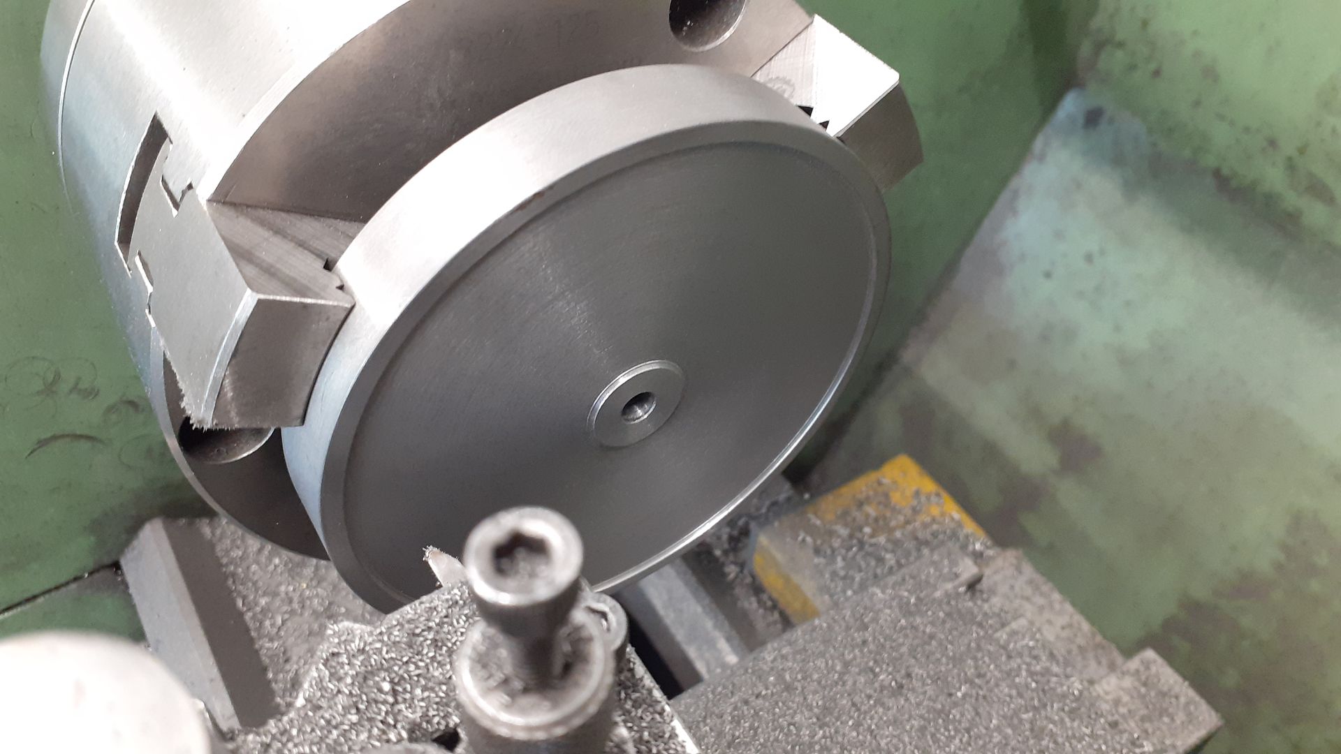
                                        Once that was done I could get a decent grip of it to turn the other side and also cut a 1mm deep recess with around nosed tool on each side to reduce the amount of milling required. The hub on the other side protrudes further to give room for the grub screw.

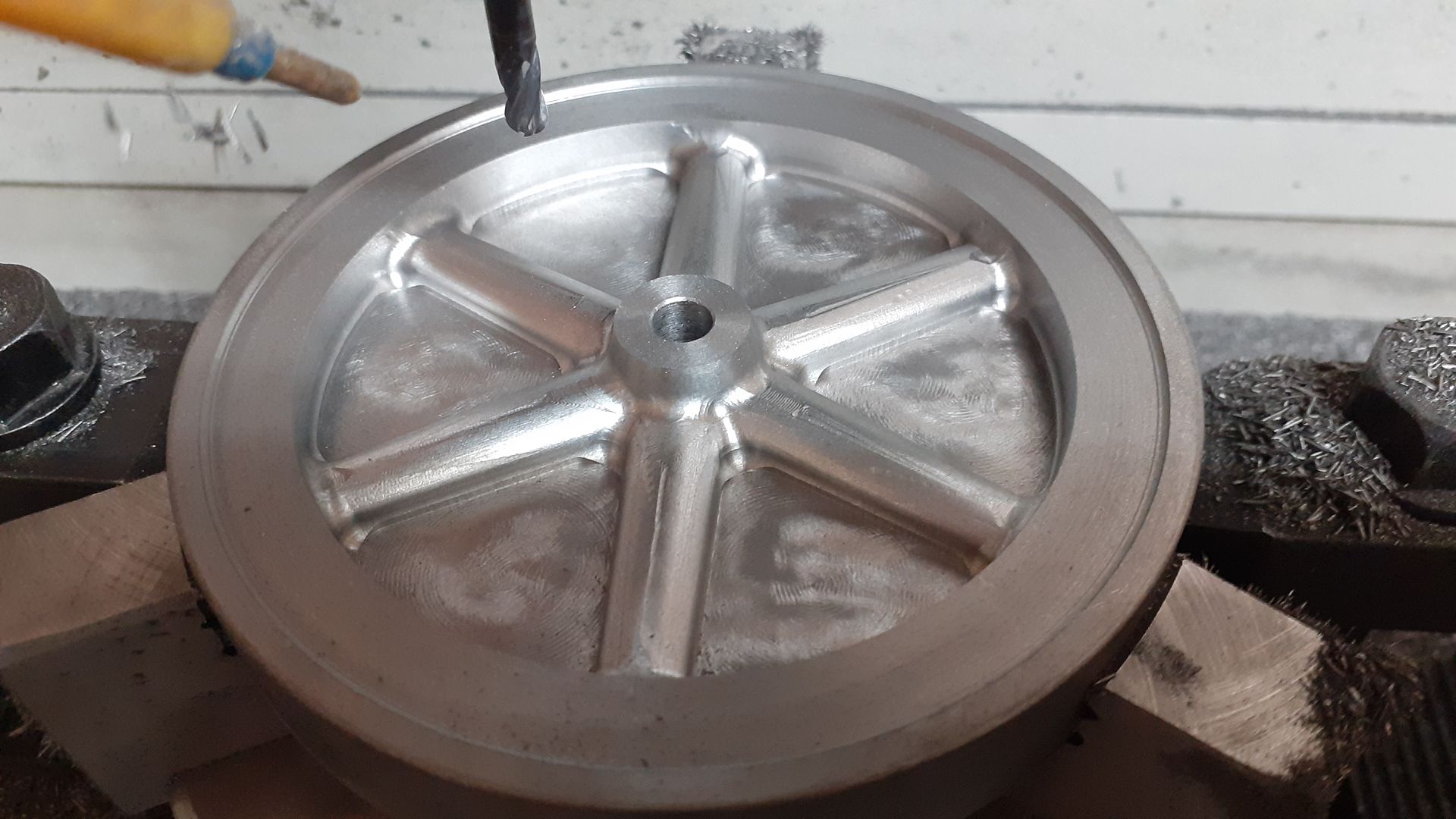
                                        An adaptive path with a 6mm cutter followed by a ramp with a 4mm ball nosed cutter took care of the roughing and finishing firstly to just beyond half depth

                                        After flipping the stock over a shallower repeat of the above took care of the rest after which a quick tickle with a Dremel cleaned up any slight machining marks and gave a little texture.

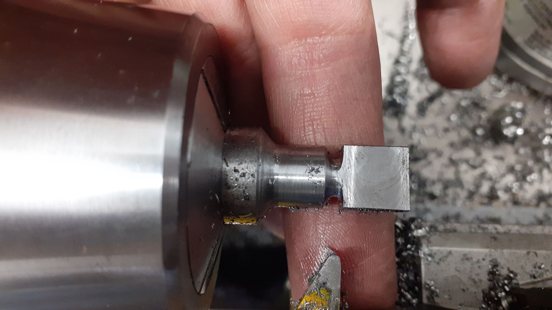
                                        I did not take many pics of the conrod, just this one that shows the beginnings of the yoke that screws into the underside of the piston crown having the waist cut with cranked round nosed tool.

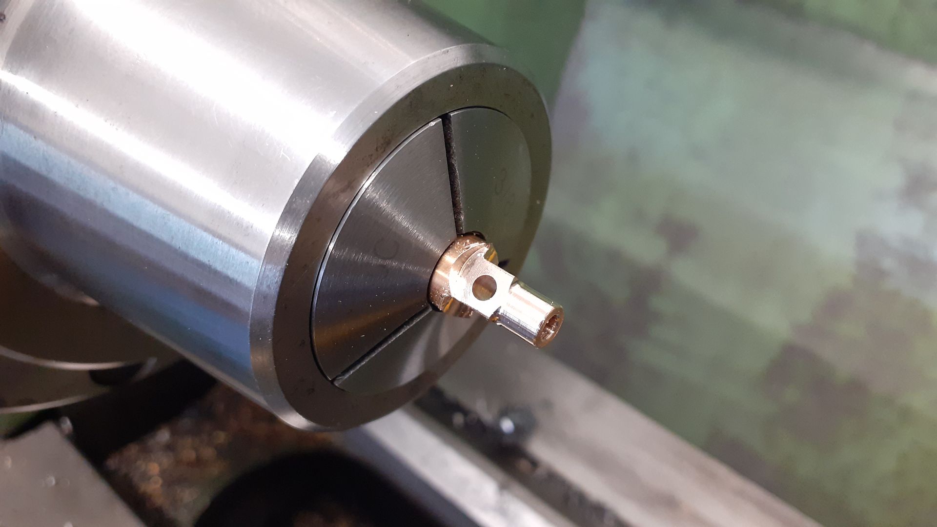
                                        And one of the little end being turned and tapped after having been milled square and a reamed 3mm hole formed

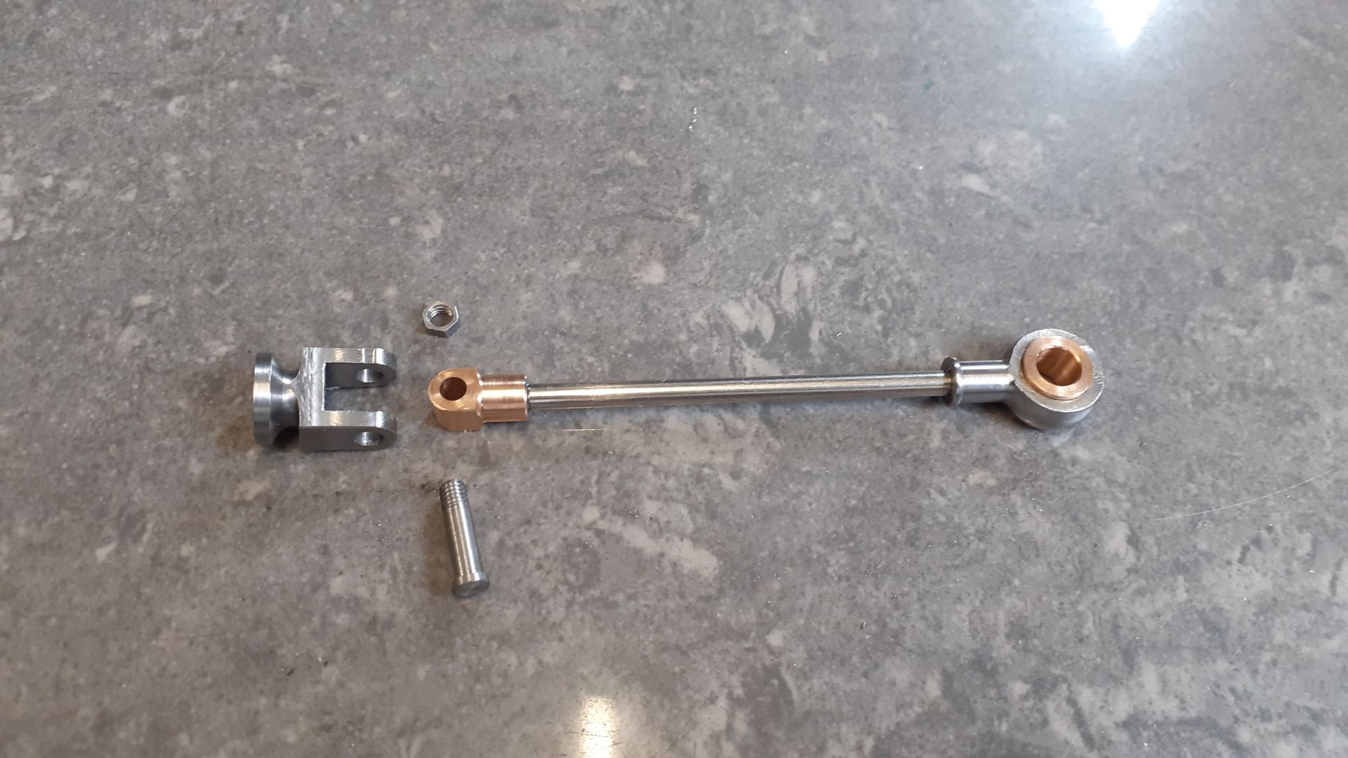
                                        But I did take a photo of all the parts before putting them together, I just used Loctite to fit the big & little ends to the rod

                                        #647799
                                        JasonB
                                        Moderator
                                          @jasonb

                                          Before I continue the build some new information has surfaced which puts the original article at a some what earlier date of 1881 (Thanks Pat)

                                          The last few parts comprise the head and valve assembly.

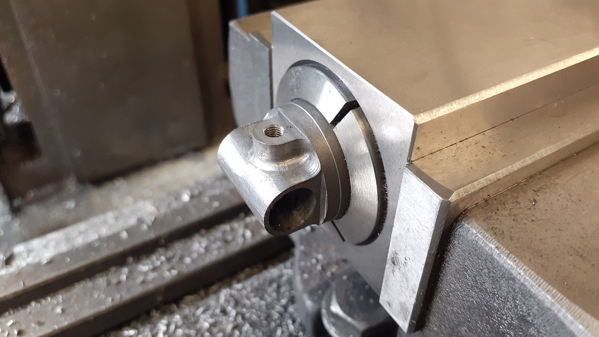
                                          As mentioned at the start the article calls for a cast head with passages cast in though the detail was not really clear enough to see exactly what was intended and the overall shape was quite boxy. I drew up something a bit more appealing to my eye and used the CNC to translate that image into cast iron. Without removing the partially machined head from the 5C block I transferred to the manual mill to drill and ream for the sleeve and drill & tap the inlet exhaust pipe connections.

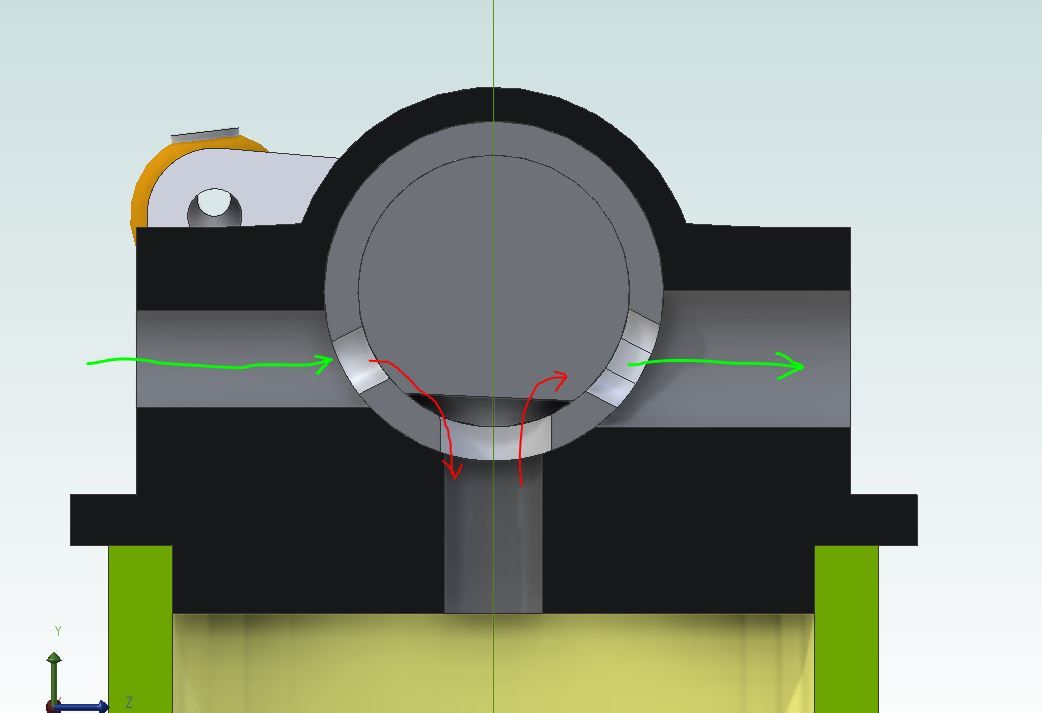
                                          Some more doodling with Alibre came up with a valve design that I thought would work, here is a section through the head. There is an inserted sleeve that has what would be the port faces on a slide valve engine milled into it, drilled passages down into the cylinder. There is then a stainless steel spindle with a flat milled onto it that will open and close the ports and connect the open one to the cylinder as it is rocked by the eccentric rod.

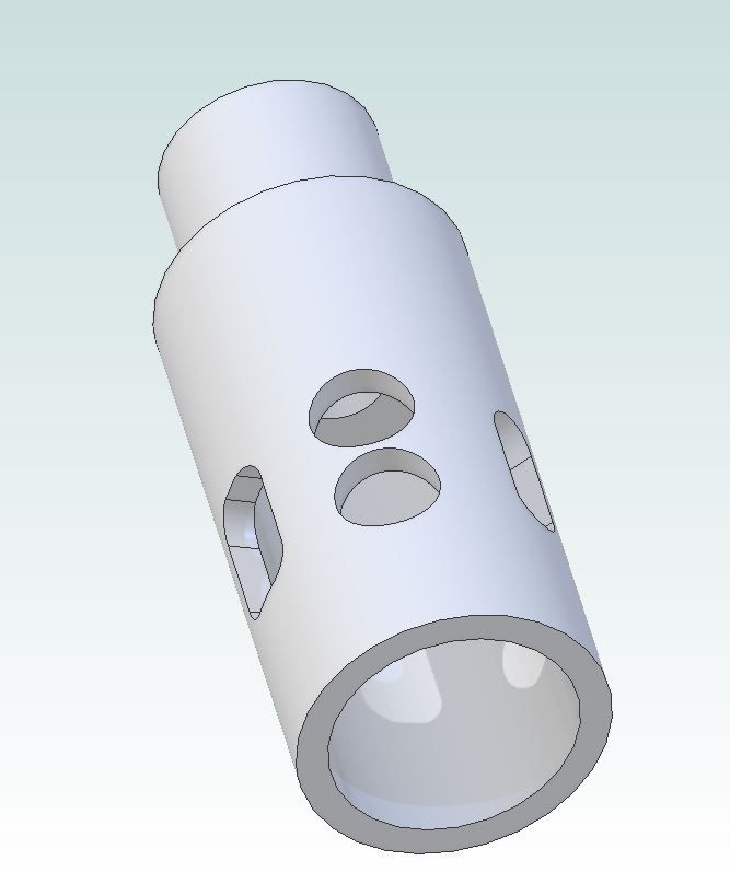
                                          This is the sleeve with the larger exhaust slot on the left

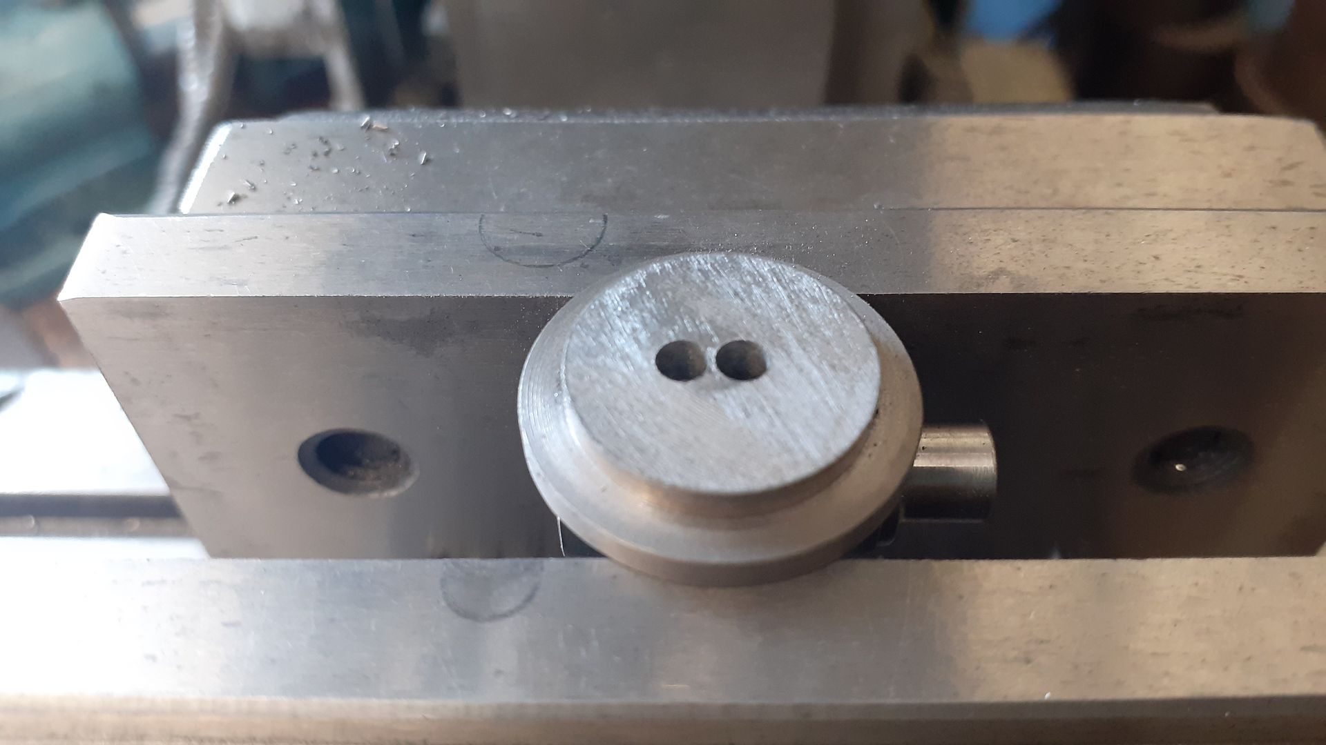
                                          Once the sleeve had been Loctited into the head the two holes were drilled

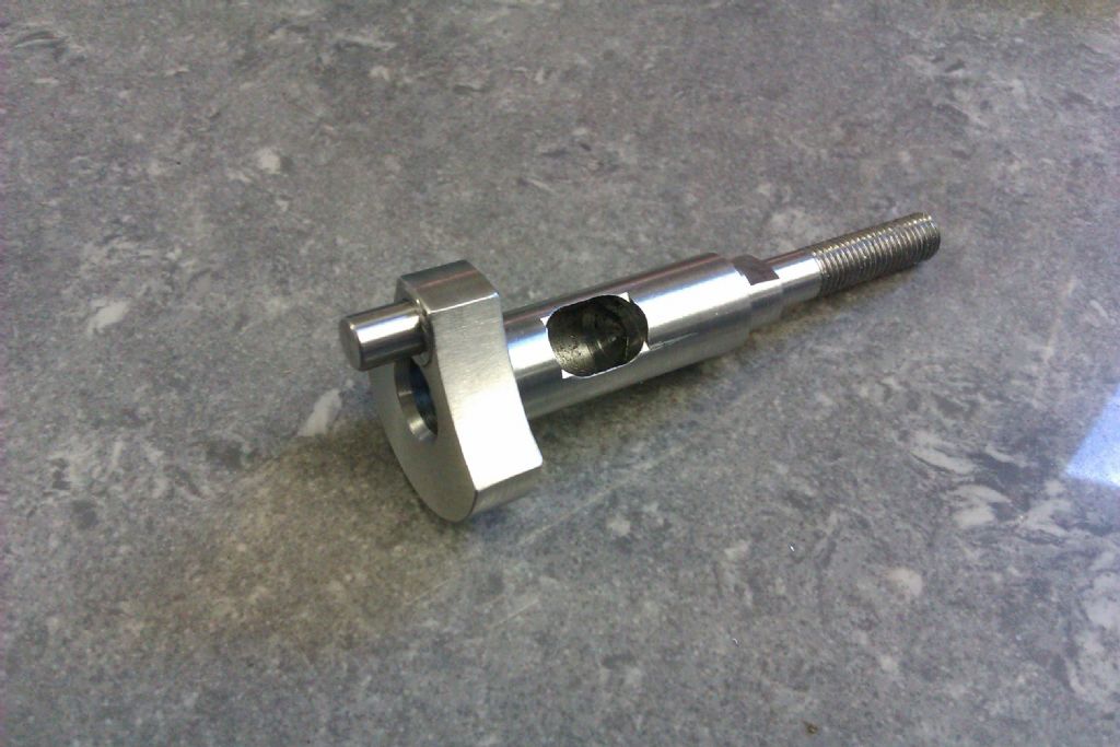
                                          This pic shows the valve spindle having had it's flat milled a 1mm hole was drilled through it's spigot and the actuation arm so they could be pinned together

                                          From an early stage I had decided to leave this engine in bare metal which I did with the exception of the "cast" surface of the flywheel which was done in a Rustoleum cast iron effect paint. I did think of bead blasting it but it would have been prone to rust so went with the paint. A piece of mahogany that I took out of a clients 110yr old house provided the base.

                                          #647800
                                          JasonB
                                          Moderator
                                            @jasonb

                                            Well that's another one crossed off the list of "future projects" but the list still seems to be getting longer :-[

                                            #647804
                                            DiogenesII
                                            Participant
                                              @diogenesii

                                              That's a nice one – I think you've absolutely nailed the '1880's-scientific' theme there.

                                              How many engines do you think you might have made now?

                                              #647816
                                              JasonB
                                              Moderator
                                                @jasonb

                                                I think that one takes me to just over 50, got the next one running last weekend so will need to start writing that up.

                                                #647866
                                                DiogenesII
                                                Participant
                                                  @diogenesii

                                                  .. that's truly impressive, I can see I need to find a lot more workshop discipline if I'm to do a fraction of that before time's up..

                                                  ..these builds you post are really helpful, not just the tips and advice, I mean the whole sense of directness and planning behind it.. 👍

                                                Viewing 23 posts - 1 through 23 (of 23 total)
                                                • Please log in to reply to this topic. Registering is free and easy using the links on the menu at the top of this page.

                                                Advert

                                                Latest Replies

                                                Home Forums Stationary engines Topics

                                                Viewing 25 topics - 1 through 25 (of 25 total)
                                                Viewing 25 topics - 1 through 25 (of 25 total)

                                                View full reply list.

                                                Advert

                                                Newsletter Sign-up