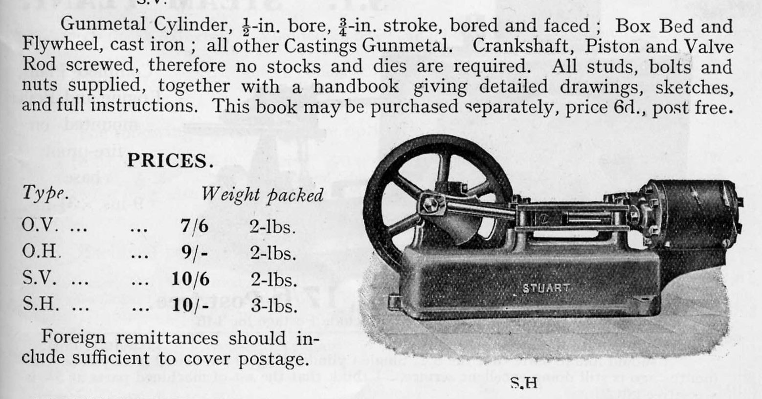
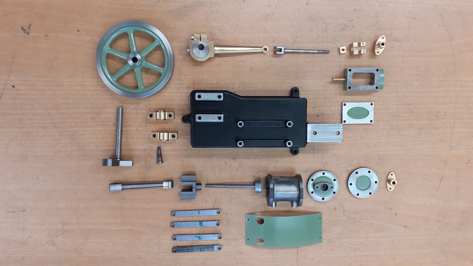
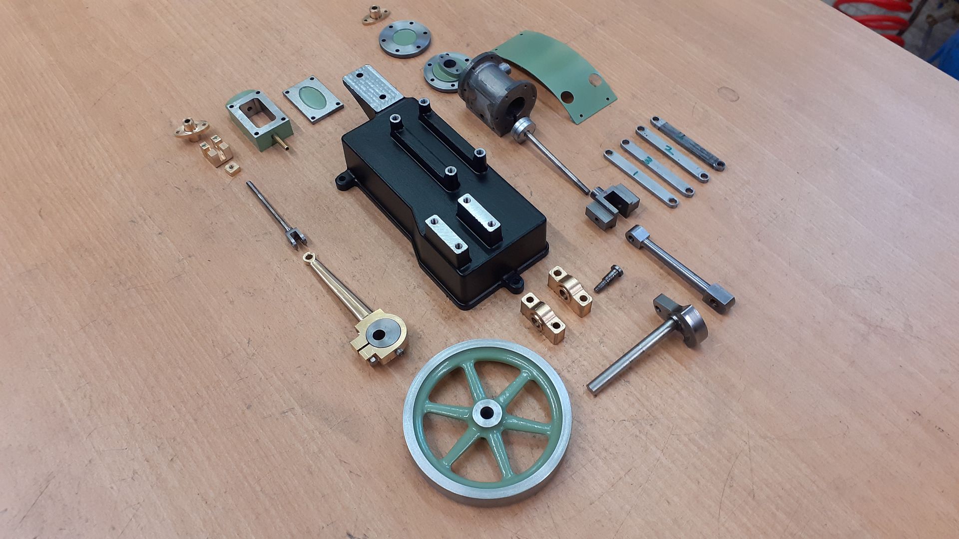
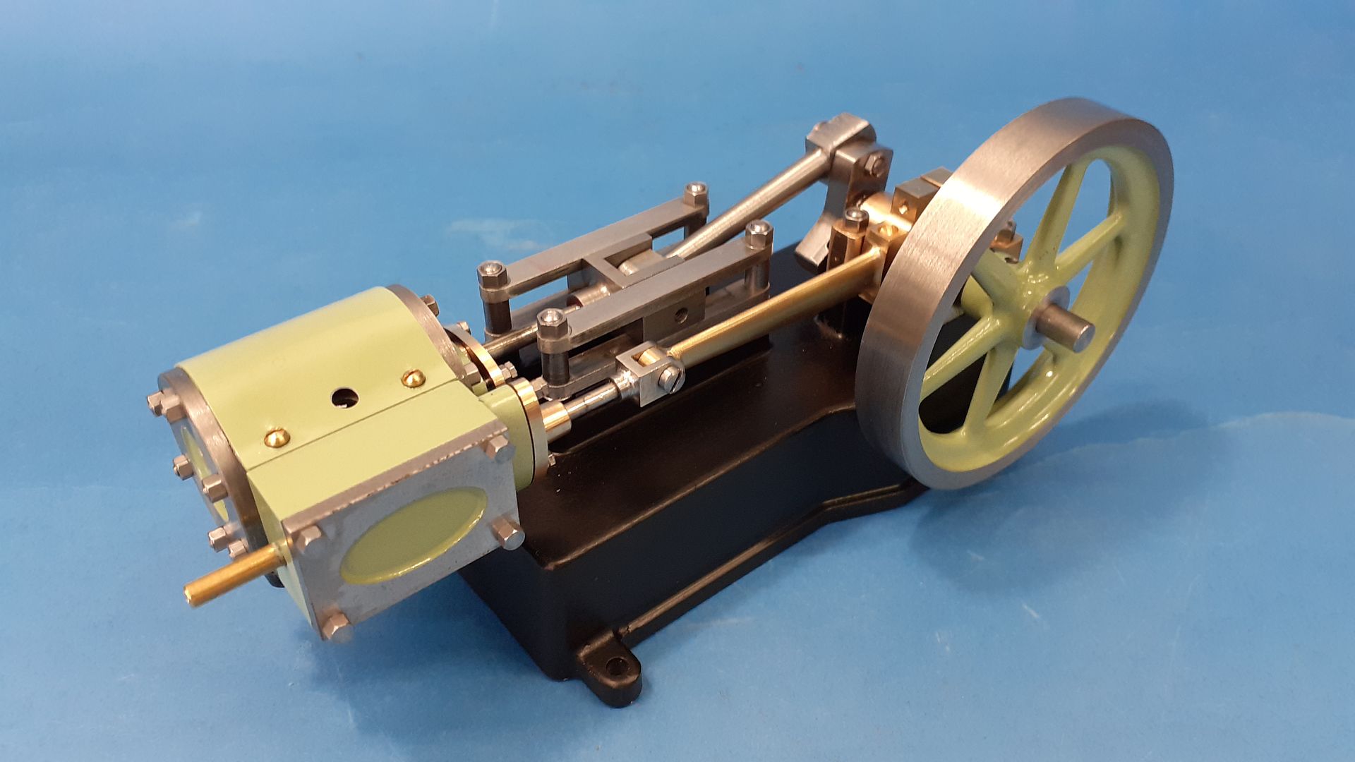
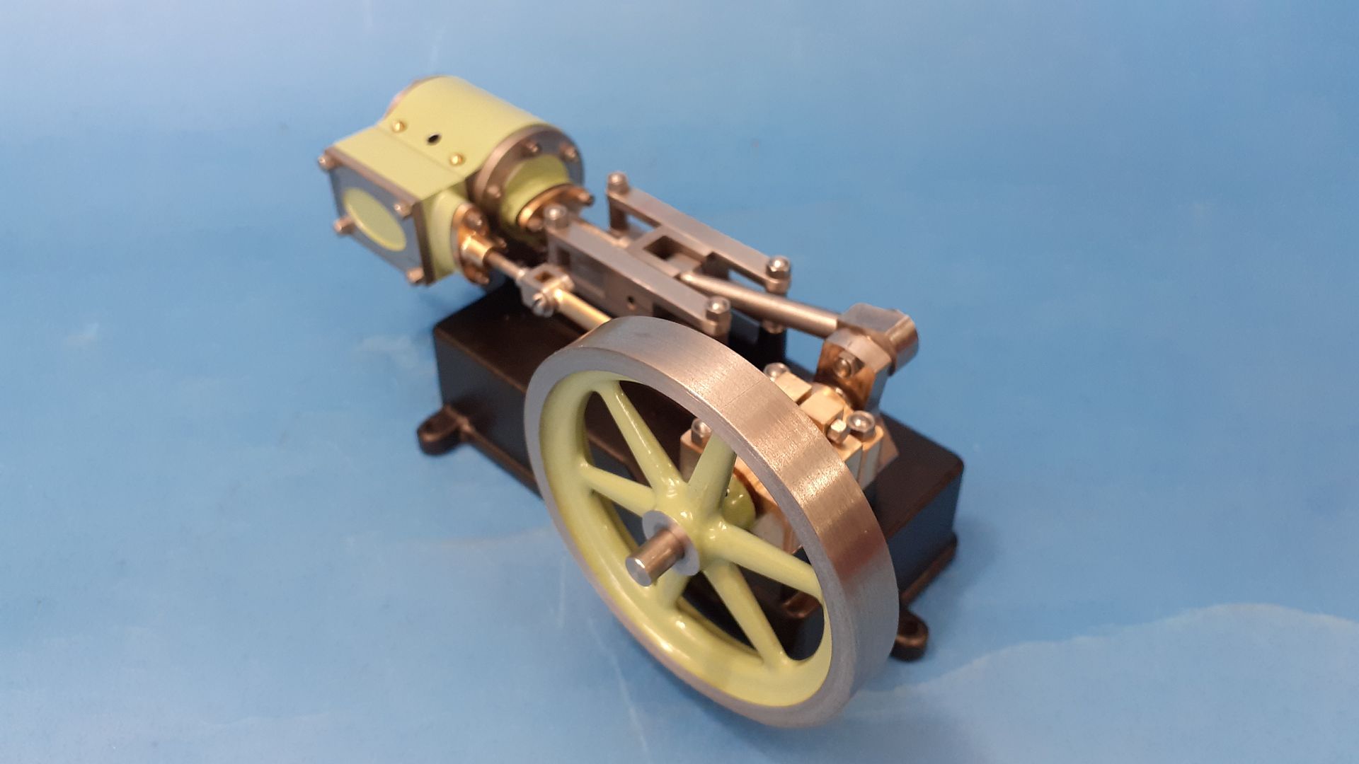
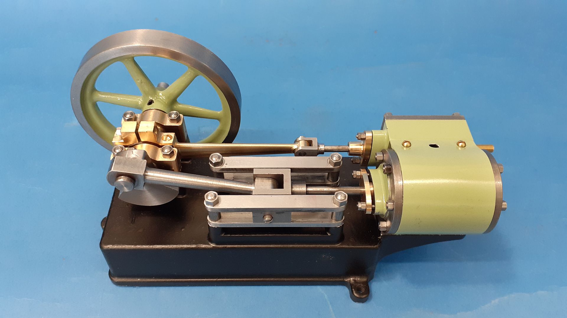
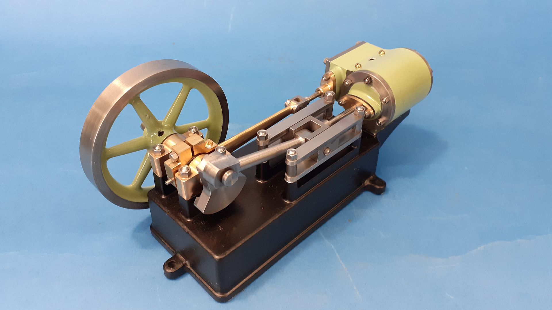
Or more precisely a replica of the Stuart Models "Progress SH"
99 years ago in 1924 Stuart introduced the "progress" range of six engines all sharing a similar bore and stroke and consisting of horizontal and vertical oscillators, horizontal and vertical slide valve engines, a mill engine and an undertype engine. Production ran up until about 1941 with only the horizontal oscillator being reintroduced a few years ago.
The subject of this thread is the Progress SH standing for Slide valve Horizontal an engine of similar style to the well known S50 with a bore of 1/2" and a stroke of 3/4"
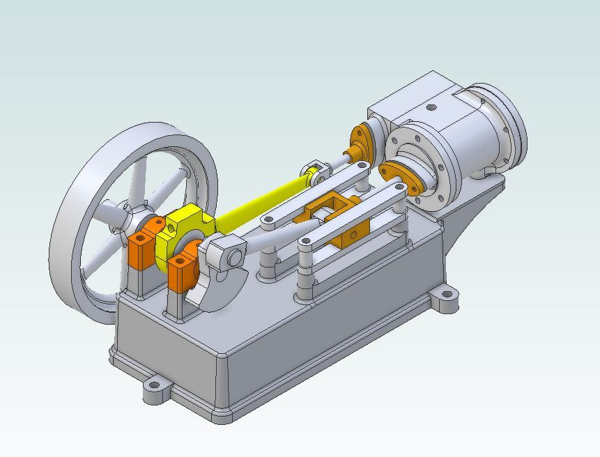
A reprint of the booklet mentioned in the above catalogue extract is still available from Tee Publishing and covers all the engines in the range with building notes as well as drawings so that is what I started with. As with my other recreations of long lost small engines I set to and redrew it in metric with a 12mm bore and 20mm stroke in Alibre, exporting some parts to F360 to make use of the CAM function to generate the G-code needed for the CNC mill.
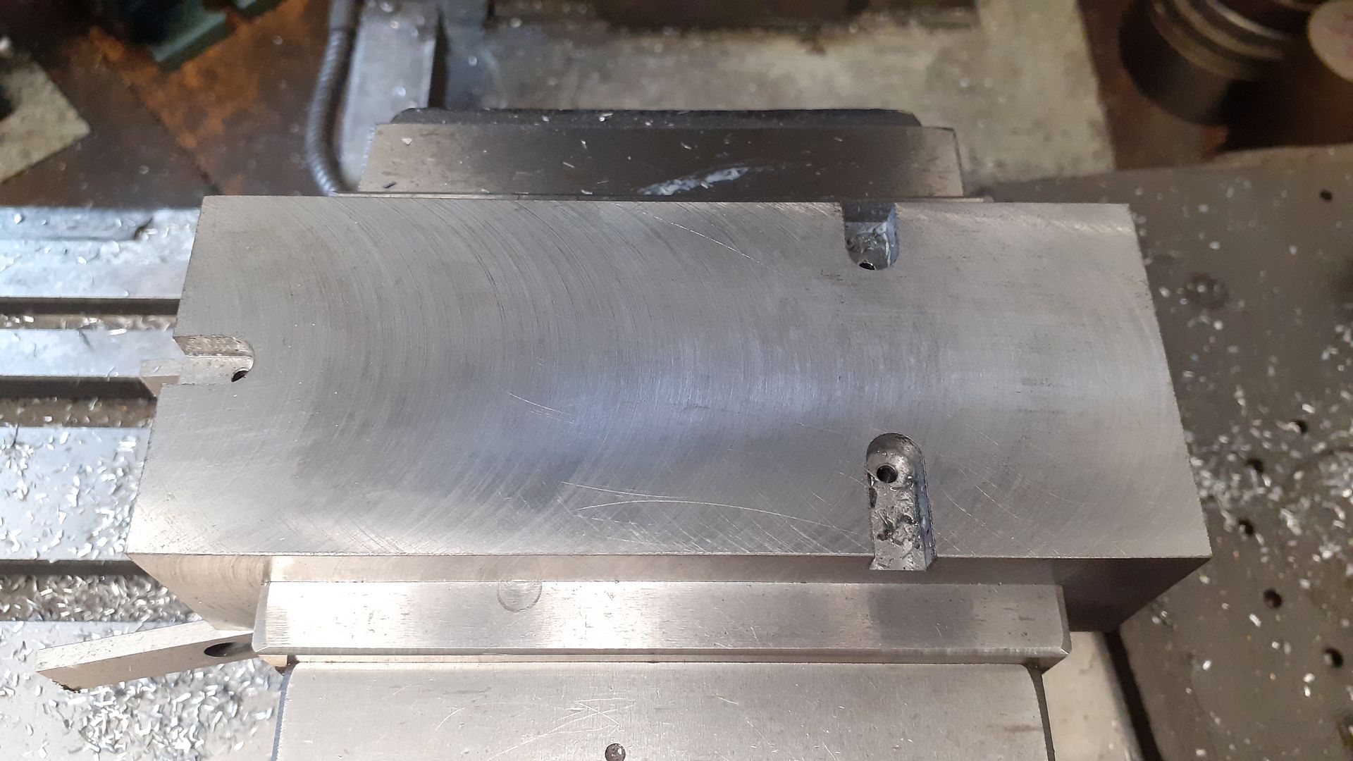
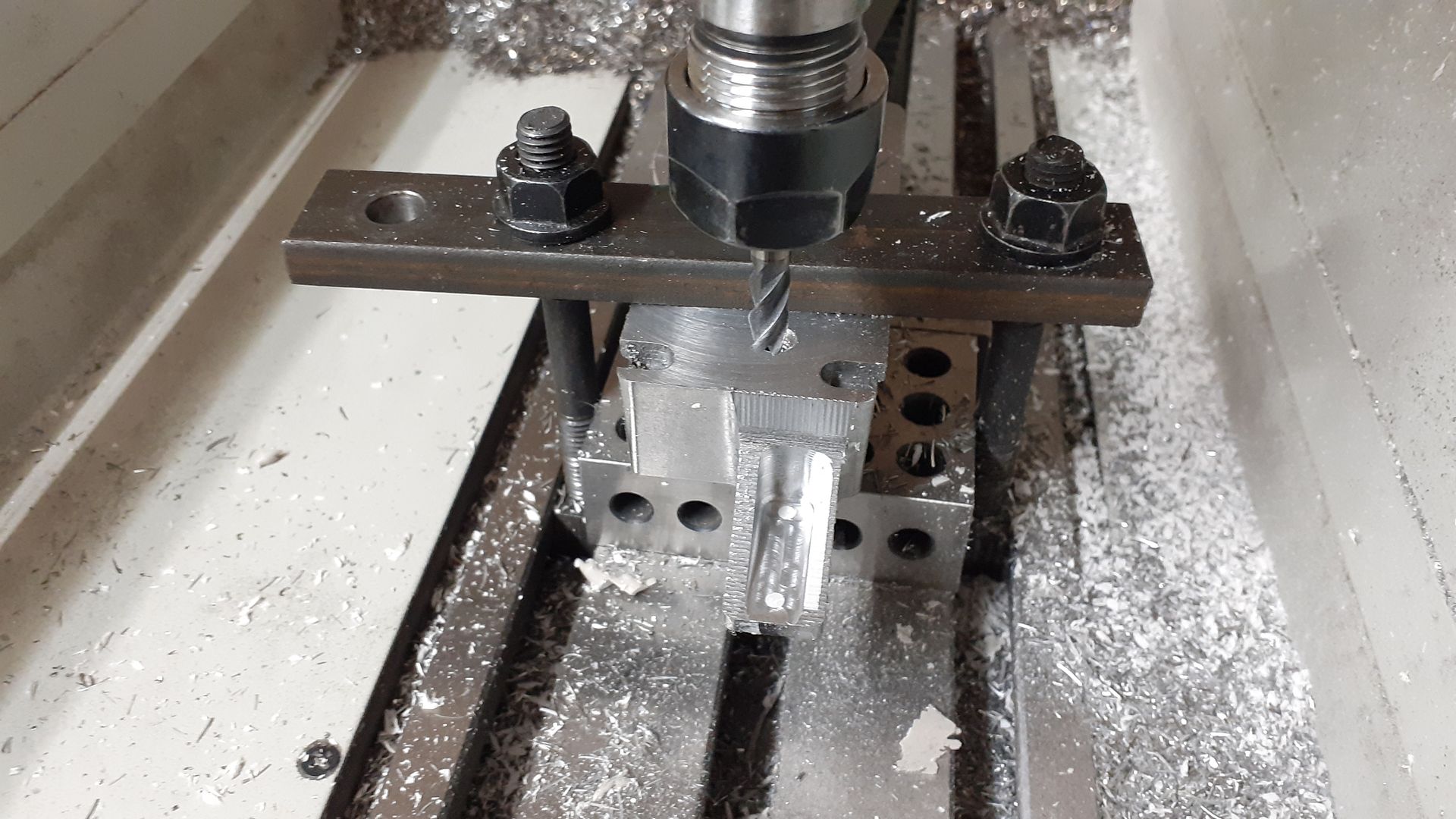
When I originally started to draw this up I had intended to build up the main bed "casting" from some 2" x 1" aluminium flat bar adding the bearing and guide rail bosses to the top as well as the cylinder support as a separate piece. However as I got closer to making a start I had second thoughts and decided that the bed would make an interesting part to cut from almost one solid block. looking around at prices it was more economical to start with 40 x 60 flat EN3 steel than 2" imperial steel or aluminium stock so a length was ordered from M-Machine and duly milled down to the required 34mm finished height with the length and width plus 2mm to give a 1mm all round machining allowance for the. While it was an easy to hold rectangular block I milled and tapped 3 pockets for the feet which will be done as separate parts to reduce the waste material. I also tapped tow M8 holes so that I could mount the stock to a block that could inturn be held in the machine vice
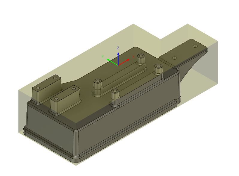
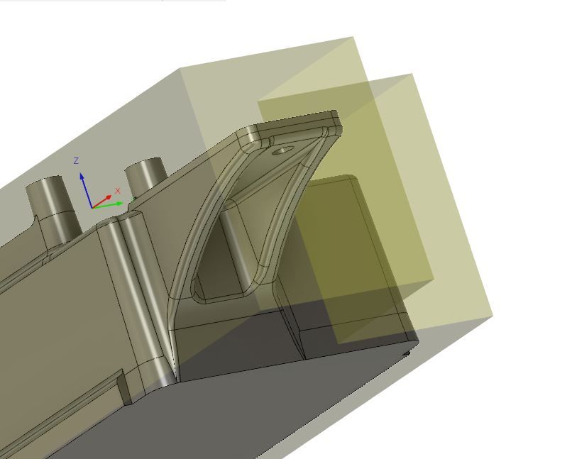
To reduce the amount of CNC time I sawed out one corner of the block and modelled that in F360 to use as my setup stock, her you can see the part lurking within the "L" shaped stock
A second setup was required to machine out the material under the cylinder support
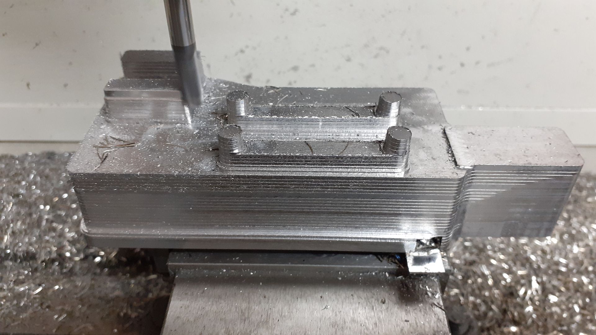
This shot shows the results of an adaptive clearing tool path that leaves a series of steps on the sloping surfaces as they all have a draft angle to mimic the casting and one of the finishing paths has just started to work it's way down around the near bearing block boss.
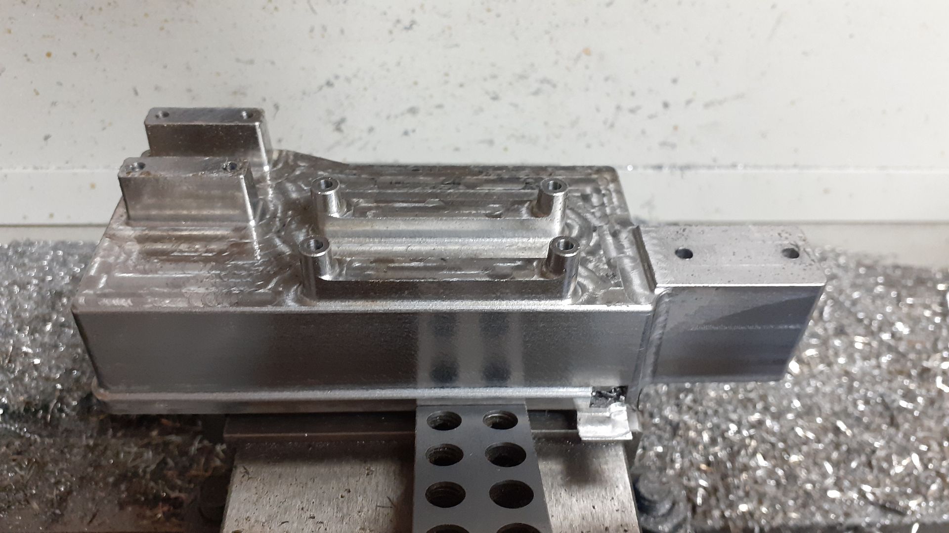
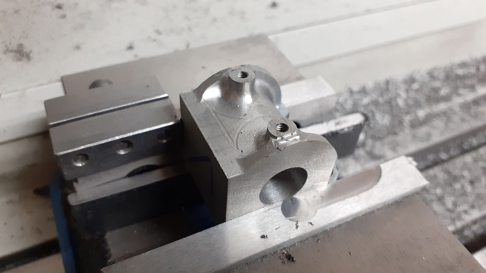
And once all the finish paths have been completed. I also drilled all the holes at this setup with the CNC but manually tapped them although I did reposition the spindle above each hole to help guide the tap vertically
From a slightly different angle the light falling on the more matt near vertical faces shows where the draft angle feathers out under the cylinder support the brighter material which is the vertical "shadow" below will be removed with the second setup
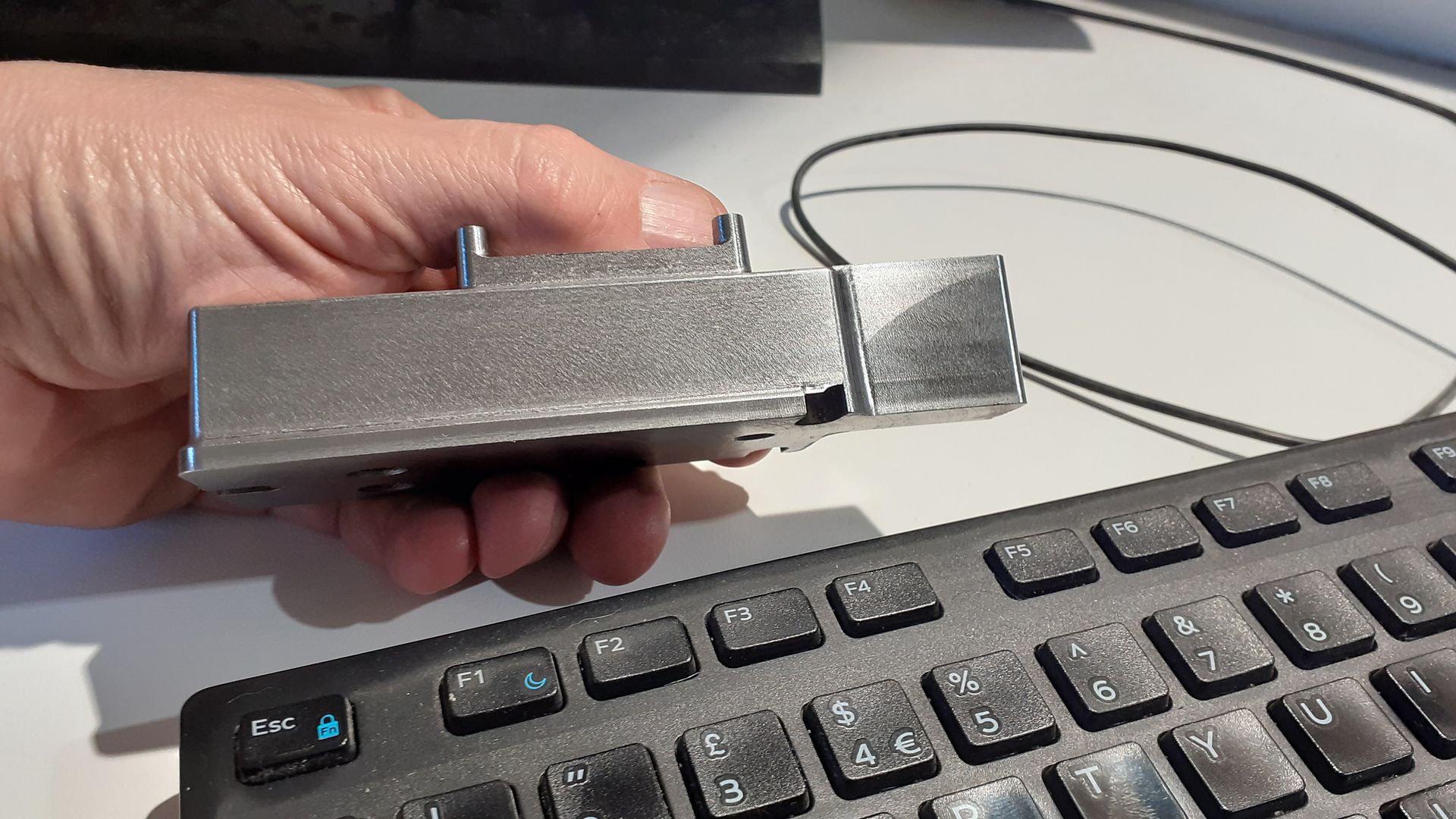
I did muck up my edge finding for the second op but was able to recover things by using some U-pol Rapid filler and running the cut again in the correct position, you can just see the lighter coloured filler on the right hand inner face of the support webs.
While the CNC was warm I also did the three feet on that doing both the milled profile and the two holes, these were then sawn off the scraps of bar, machined to 4mm thick and then screwed and JBWelded into the pockets on the underside of the bed.
I see you use a version of Alibre. The results always look very good. And it's great to see the old Stuart models being 'reborn'.
One day I'd like to acquire some CAD/CAM s/w, objective being to eventually use it on a (also to be acquired) 3D printer. Do 3D printers require G code or does (whatever version of ) Alibre come with everything one would need?
All levels of Alibre software can export designs as STL (which is the starting point for 3D printing). 'Slicer' software processes the STL file into g-code to drive the 3D printer.
There are generic slicer packages and ones tied to specific printer brands – you can pay for slicer software, but there are very competent free options.
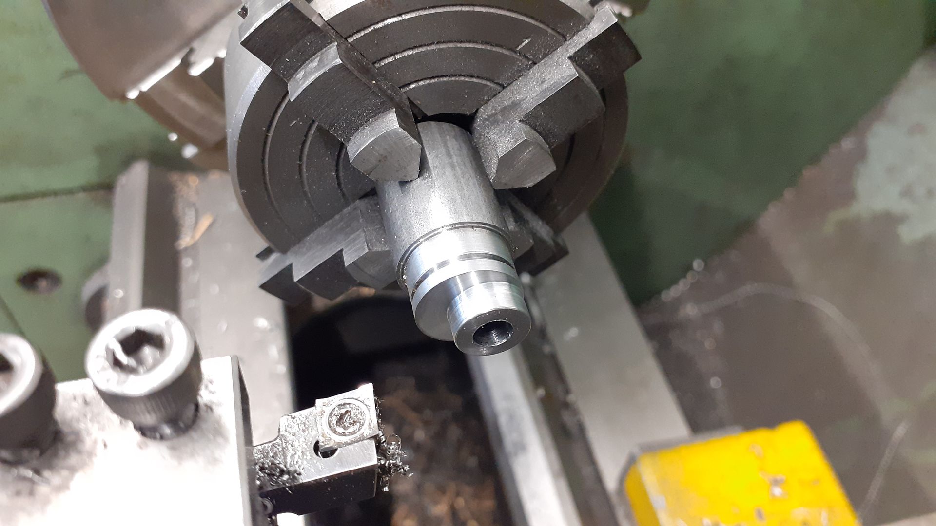
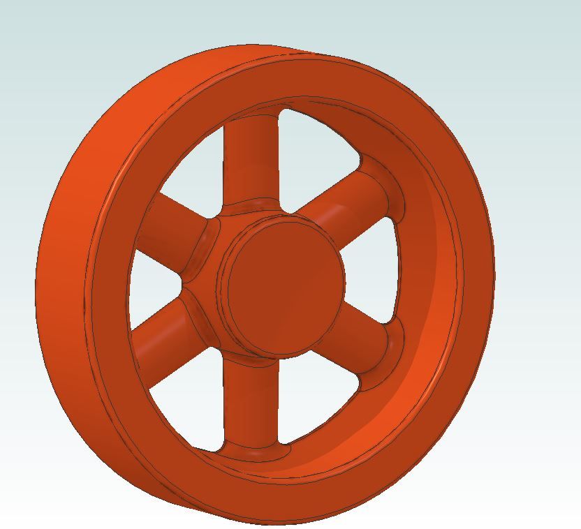
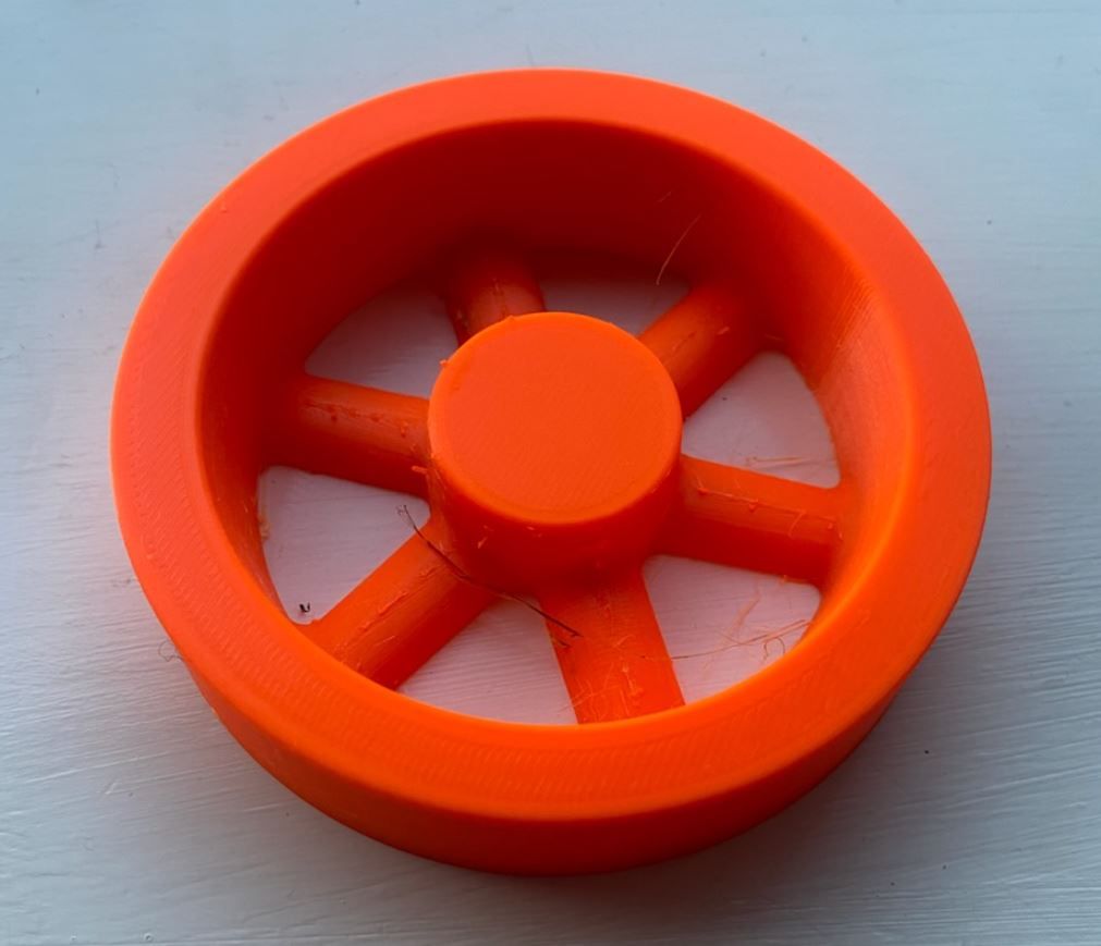
As an example the question of a missing pulley casting came up on MEM forum last week, someone dropped me in it saying I could CNC a pattern. I saw the post and within a few mins had put up an image of the pulley. Turns out the person has a 3D printer so a couple of mins more work adding machining allowance and draft angles and The pattern was ready to export as both STL and STP files which I e-mailed to him. He was printing within half an hour having processed the file through Prusa's own slicer software.
Also last week I sent someone else a complete assembly of a Stuart Victoria, waiting to see how that comes out printed with a Resin Printer
As with my other recreations of long lost small engines I set to and redrew it in metric with a 12mm bore and 20mm stroke in Alibre, exporting some parts to F360 to make use of the CAM function to generate the G-code needed for the CNC mill.
Why do you model in Alibre and export to F360 for CAM? Why not do the modelling in F360 too?
My apologies. I had assumed it was Jason that had so quickly responded. Anyway, thanks to you both.
It does seem a very potent design/manufacturing prodecure, certainly for small batch production.
Am I correct in thinking that if one didn't have a 3D printer or CNC machine, then Alibre could just as quickly 'draw up' dimensioned drawings of the Pulley and electronically send them to an iPad next to the manual mill or lathe?
I was trained to BS308 so have a reasonable understanding of drafting. But alas, missed out on the next-gen revolution ie CAD ….by then I had moved in to the engineer ranks where we sketched out our ideas and passed them to the CAD DO.
As with almost all 3D CAD packages – once you've produced the 3D model, generating traditional 2D projected views in a drawing and adding dimensions is simple. You just have to decide which views you want to include, add dimensions as desired, the dimension values are derived automatically from the 3D model (and will update if you edit the model).
The finished drawing can be published as a PDF, which is probably simplest way to share it to another device.
I've have a number of projects on my plate at the moment but I guess it wouldn't hurt to get a copy of Alibre Atom 3D, even if only for the 30 day trial.
The 30 day trial is a great way to check out the software – make sure to get the Atom3D trial if that is the product level you are interested in, as the Alibre Design trial includes extra capabilities that you'll miss if you later switch to Atom3D. The Atom3D interface is simpler too, so quicker to learn.
There is Atom3D specific training material available here
There is also an active user forum. If you get stuck during the trial, rather than waste time, reach out to the reseller or to Alibre support for help. There's also the built in Help.
Be aware there is a mindset shift from 2D to 3D – some really struggle to make the change, for others working in 3D is actually more intuitive.
Gary, having used Alibre for over 10 years I have a lot of files that I do still go back to and I'm also quite happy and conversant with Alibre so don't really want to go with something else.
F360 in it's non commercial form is fine for the small amount of CAM that I use it for and as I also tend to use Alibre for my work as well as using DXF and DWG output for hobby use it would mean having to pay for F360 too. At the moment I opt for the yearly maintenance for Alibre Professional and that is less than the more expensive yearly F360 licence would not really be worth paying for both.
I will do the odd tweak of an imported STP file in F360 such as filling in a hole so the CNC does not try to machine it out or as I have done on this bed part model the shape of the stock.
Ches, as David says I find a pdf output the best way to share my drawings with others and they also go to our editors for publication in the mag. This will give you an idea of the output. Though for my own use I tend to just pull the dimensions off the 3D model and sketch them out onto a scrap of paper in most cases.
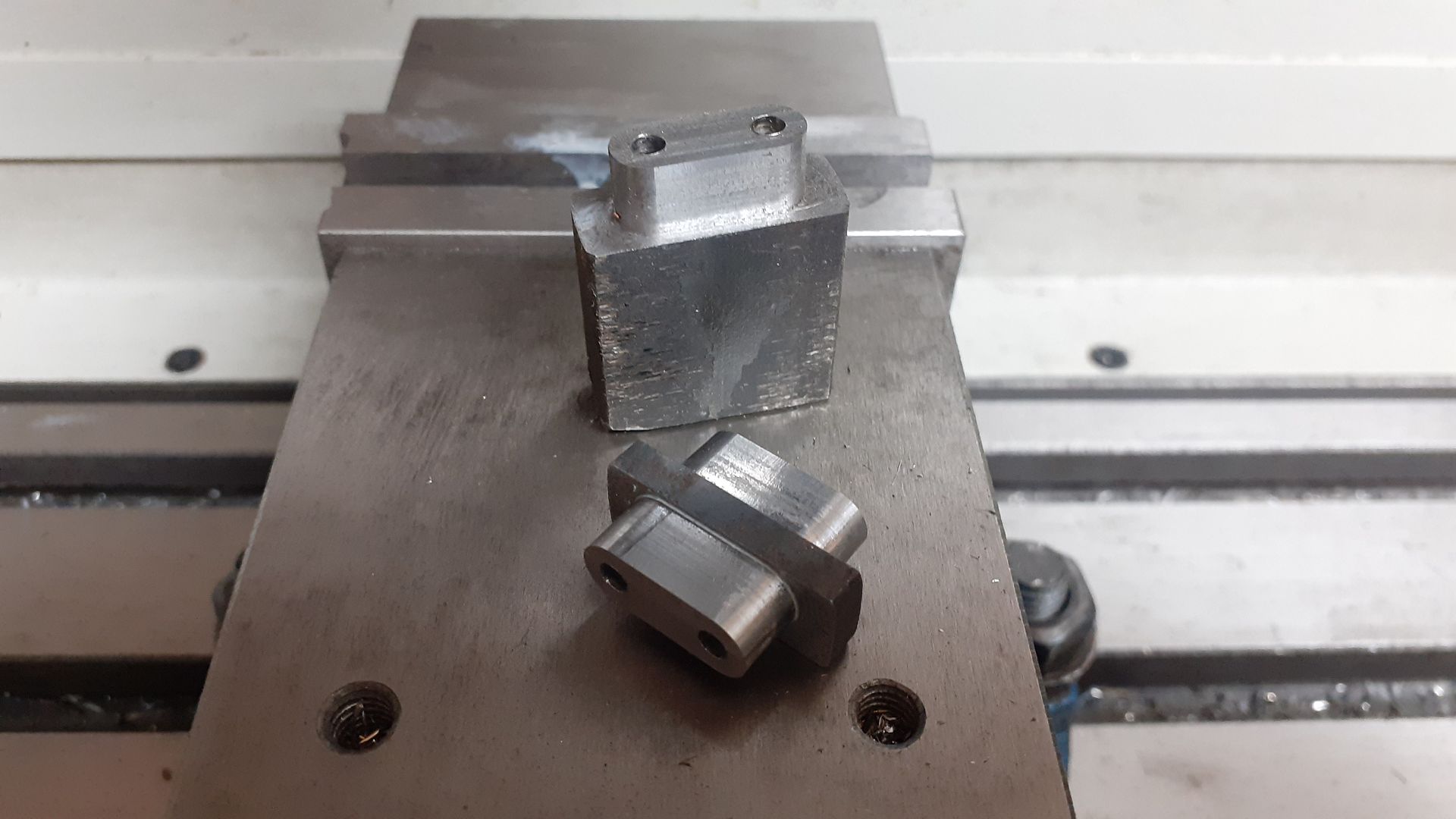
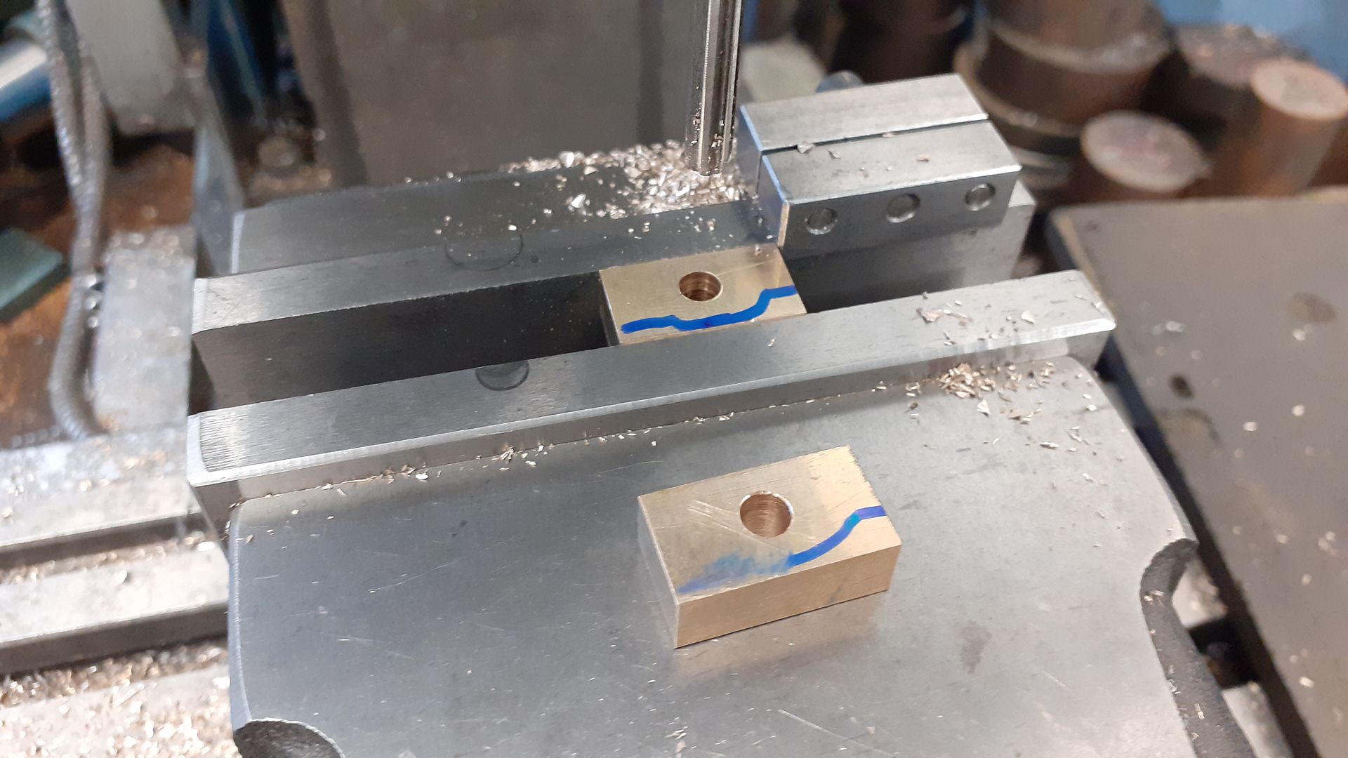
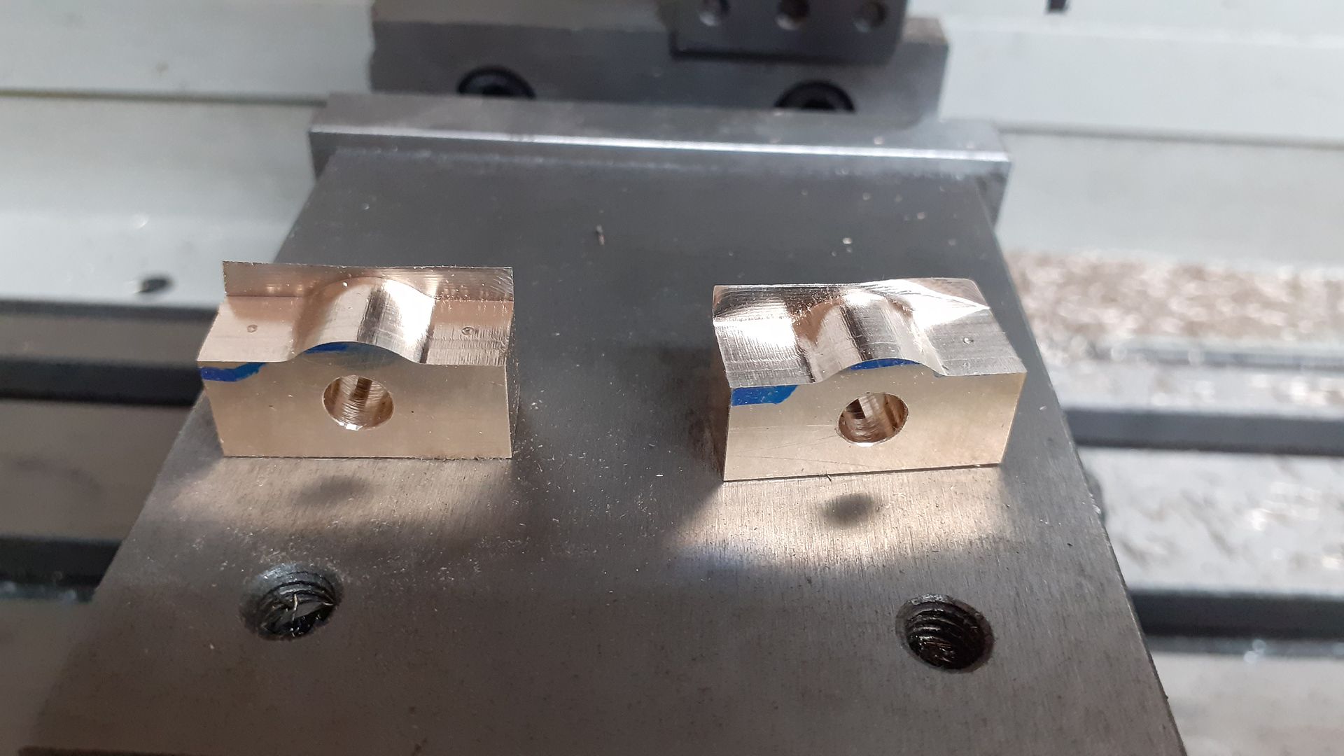
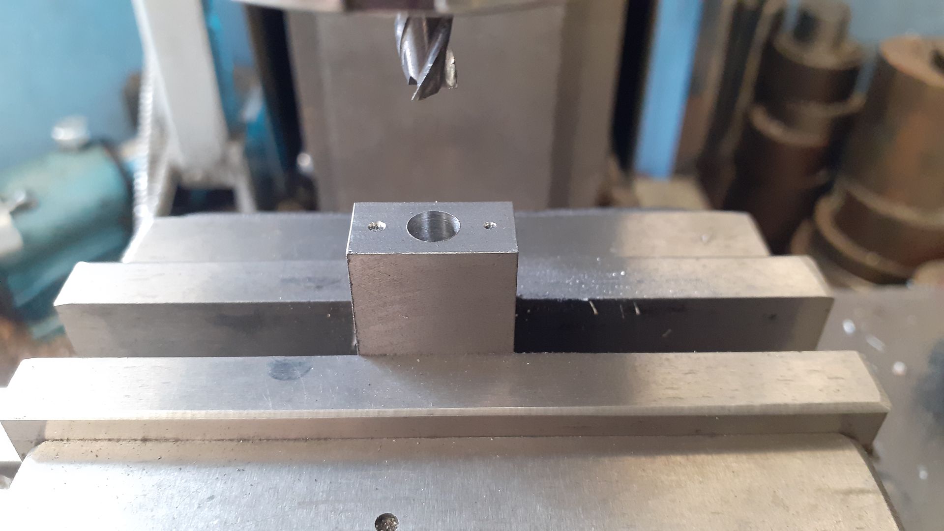
The main bearings started life as two pieces of bronze that were milled to overall size before being drilled and reamed 5mm
I then used the CNC mill to shape the tops to profile. As the flute length of the 3mm cutter I was using was 8mm was the same depth as the stock I did not quite run the adaptive and contour cuts to the full depth of the material.
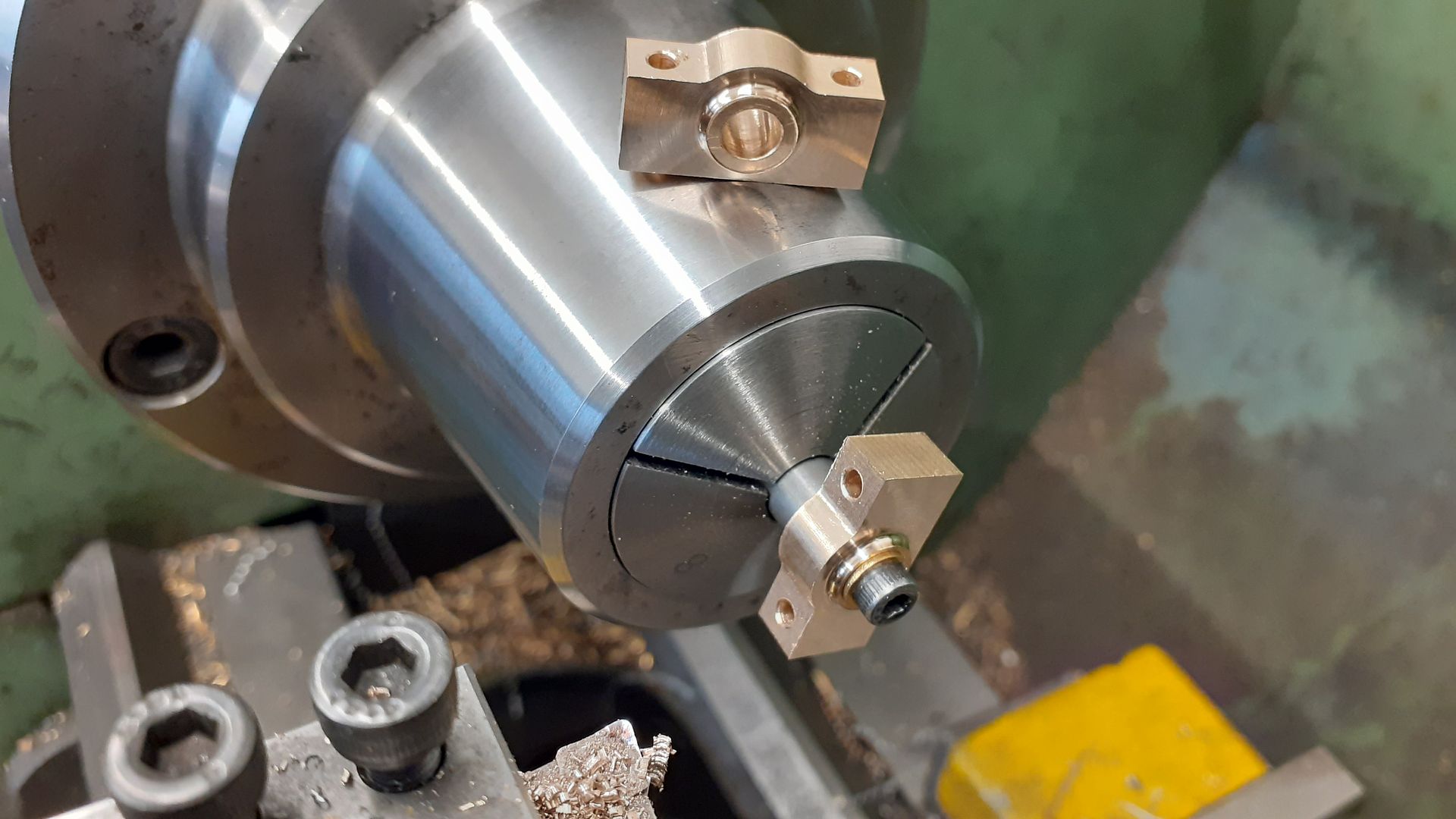
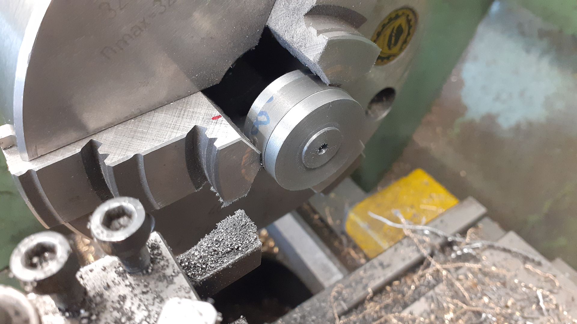
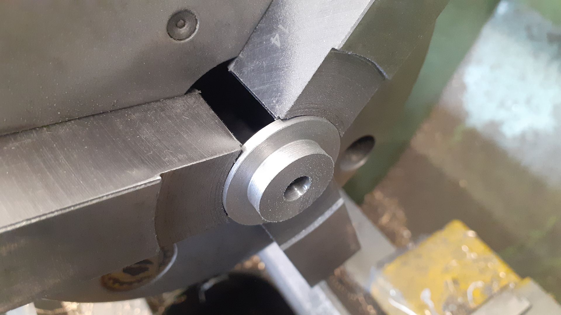
They were then mounted onto a simple arbor so that each side could have 1mm turned off just leaving a raised boss around the hole, I used a CCGT insert with 0.8mm tip radius to leave a nice internal fillet.
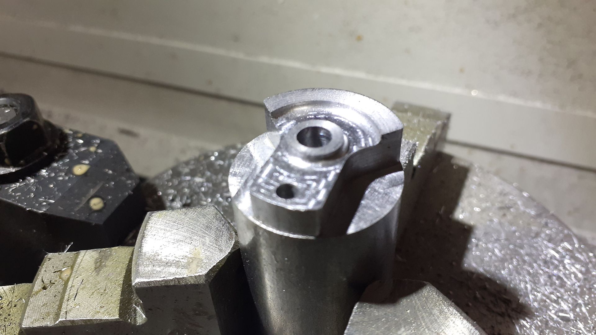
A piece of steel bar was faced, drilled and reamed 5mm and then transfered to the CNC to have both the outer profile and the recessed areas milled away as well as drilling the offset hole for the crank pin.
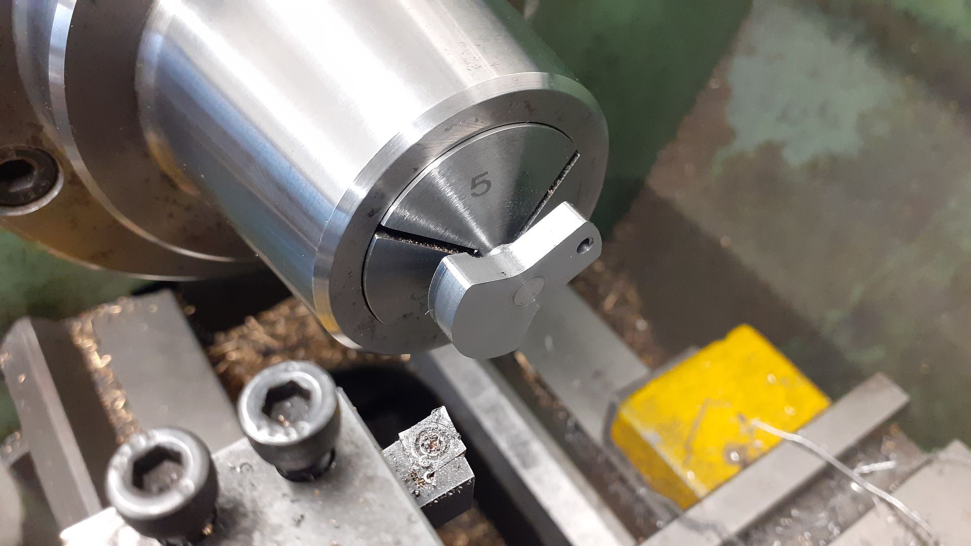
After sawing the crank off from the end of the bar it was Locteted to a length of 5mm PGMS and when set the end was faced back to thickness while holding the shaft in a collet, this gets the face perpendicular to the shaft regardless of any misalignment there may be in the Loctite joint
The two cylinder end covers were worked on either end of a short stub of 30mm cast iron bar
And then after sawing in half the external faces were machined, here the one for the piston rod end has had a rough boss turned which will be shaped into an ellipse later.
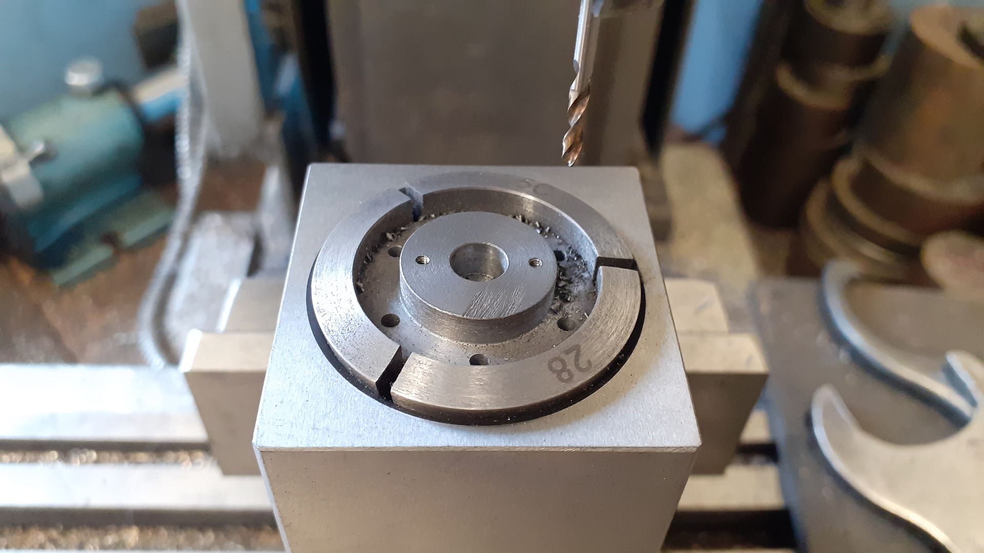
My largest 28mm 5C collet in a block held the covers while they were drilled 2mm for the studs and tapped M1.6 for the gland.
I also made a start on the valve chest, machining some cast iron to overall size, drilling and counterboring for the valve rod and it's gland and also tapping M1.6 for the gland studs.
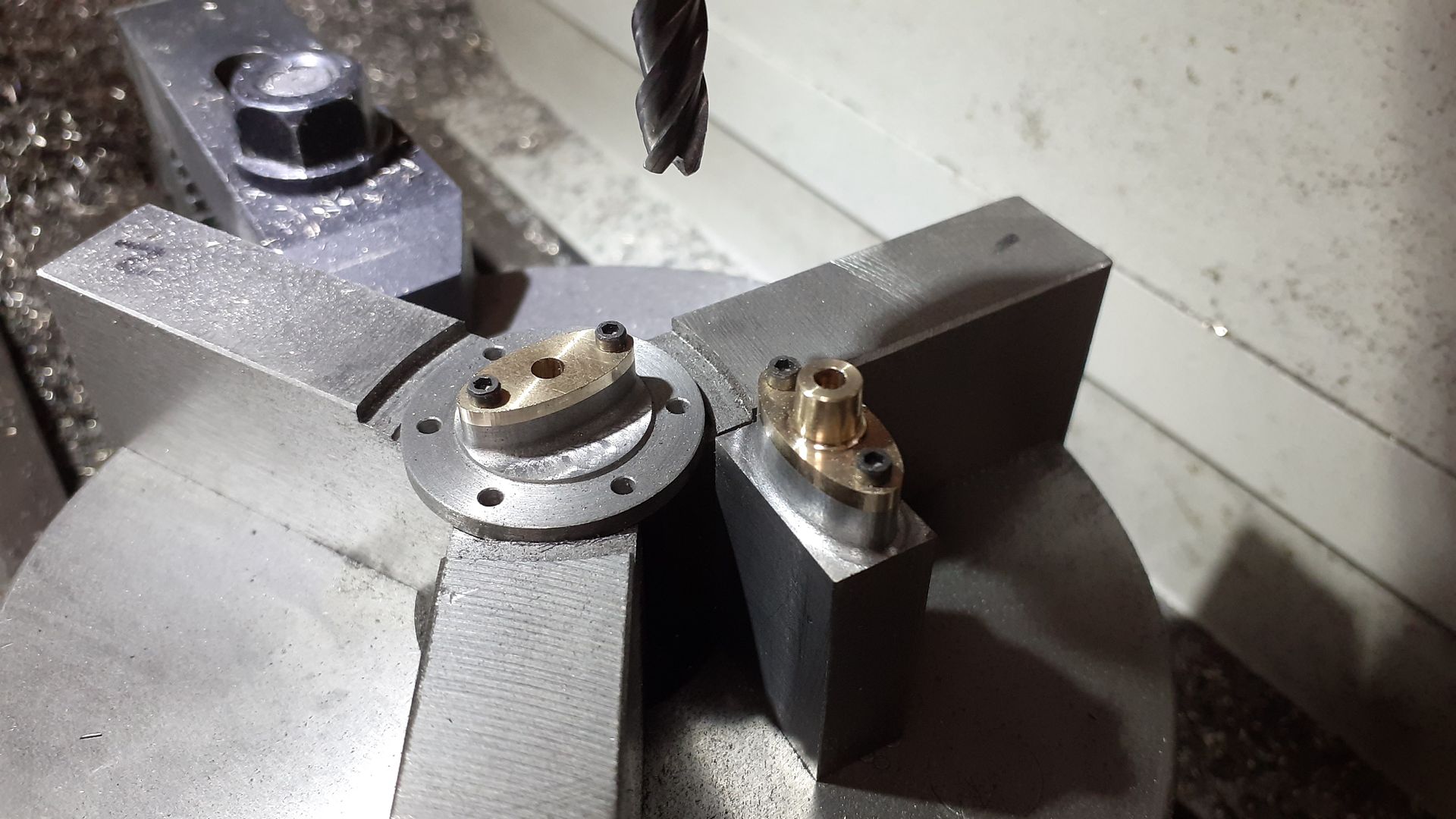
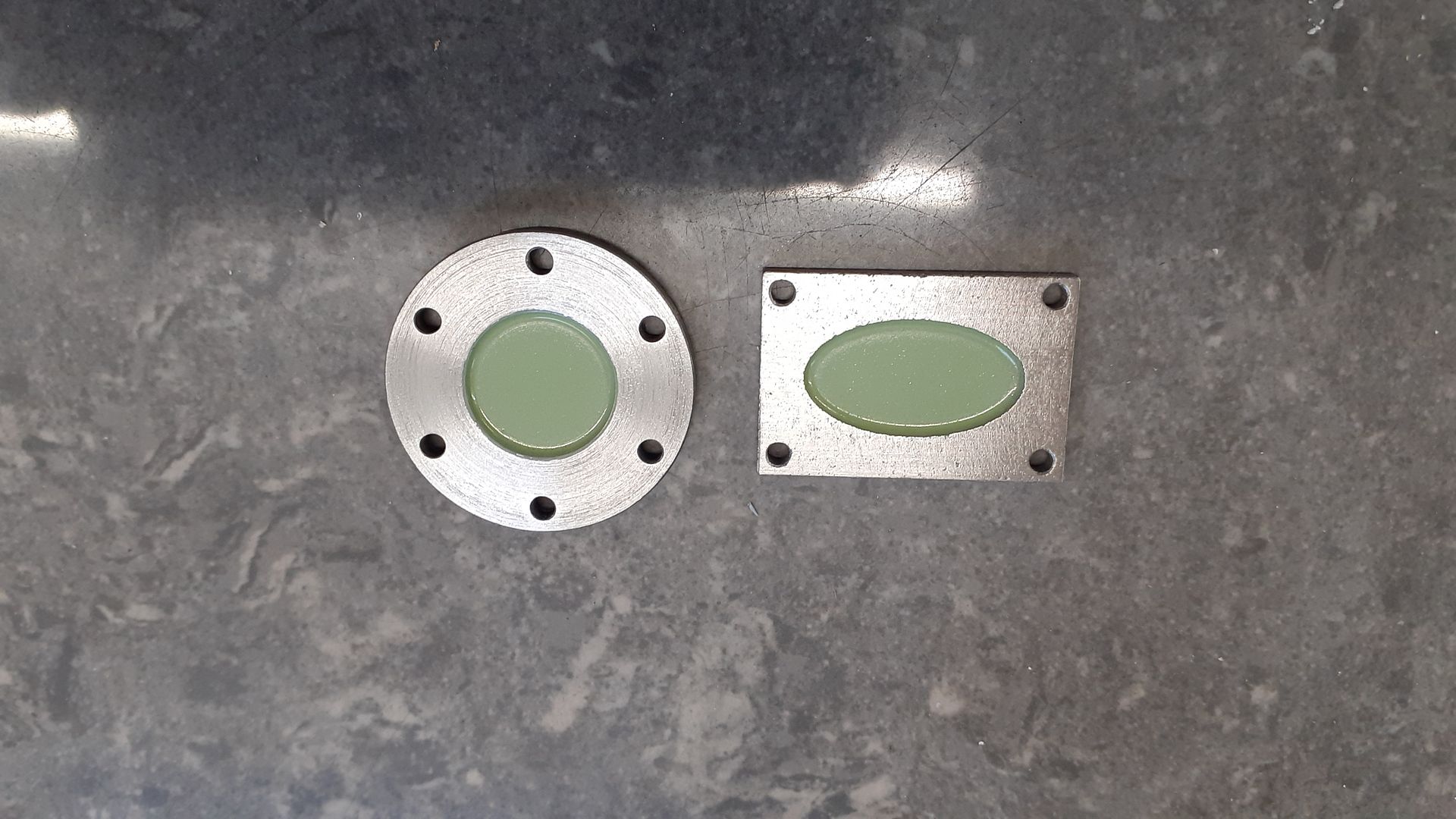
Two glands were turned from bronze bar and then screwed to their respective parts which were then machined as one. The CNC makes a good job of machining true ellipses and combined with a cutter with 1mm corner radius leaves a nice fillet in the internal corners. Most of the images of existing engines I found had the gland boss horizontal rather than vertical as shown on the General Arrangement so I set mine out the same as it is easier to get to the studs at either side than having one tucked down at the bottom of the engine
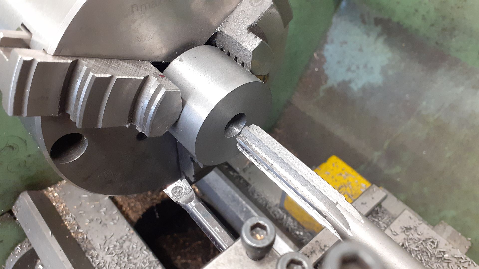
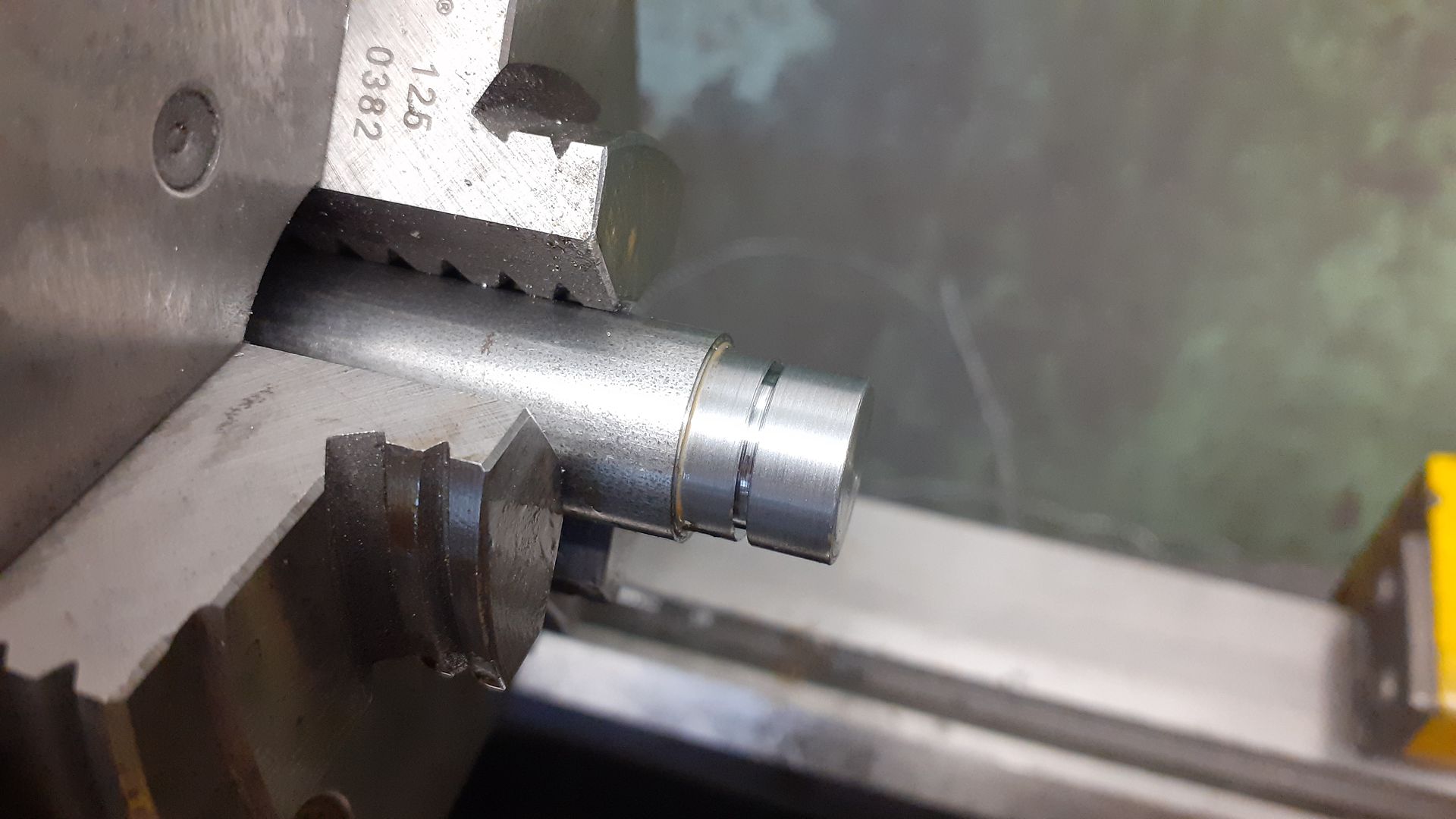
The cylinder started life as a piece of 40mm cast iron bar that was faced and cleaned up on it's OD before turning around in the 3-jaw to face the other end to the finished 28mm length before drilling, boring and then reaming 12mm.
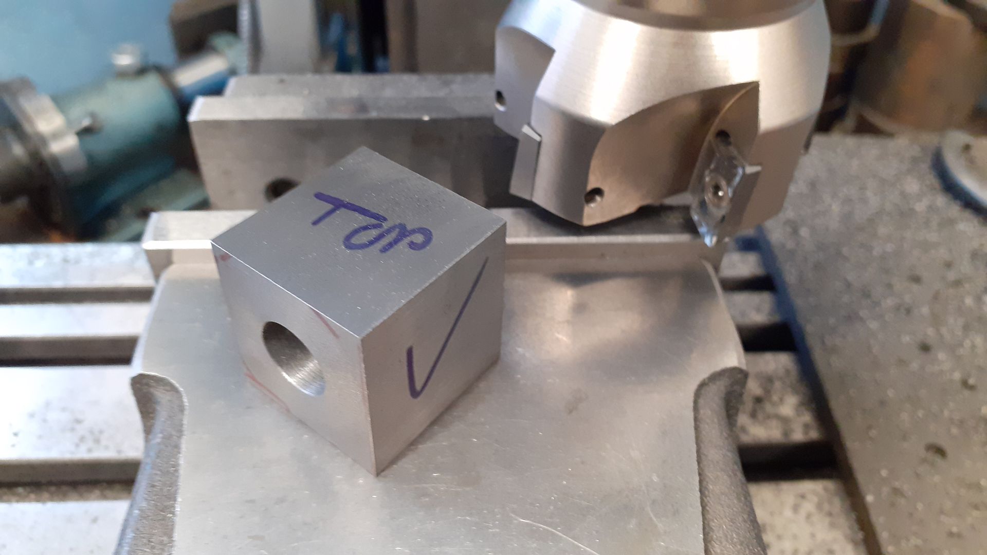
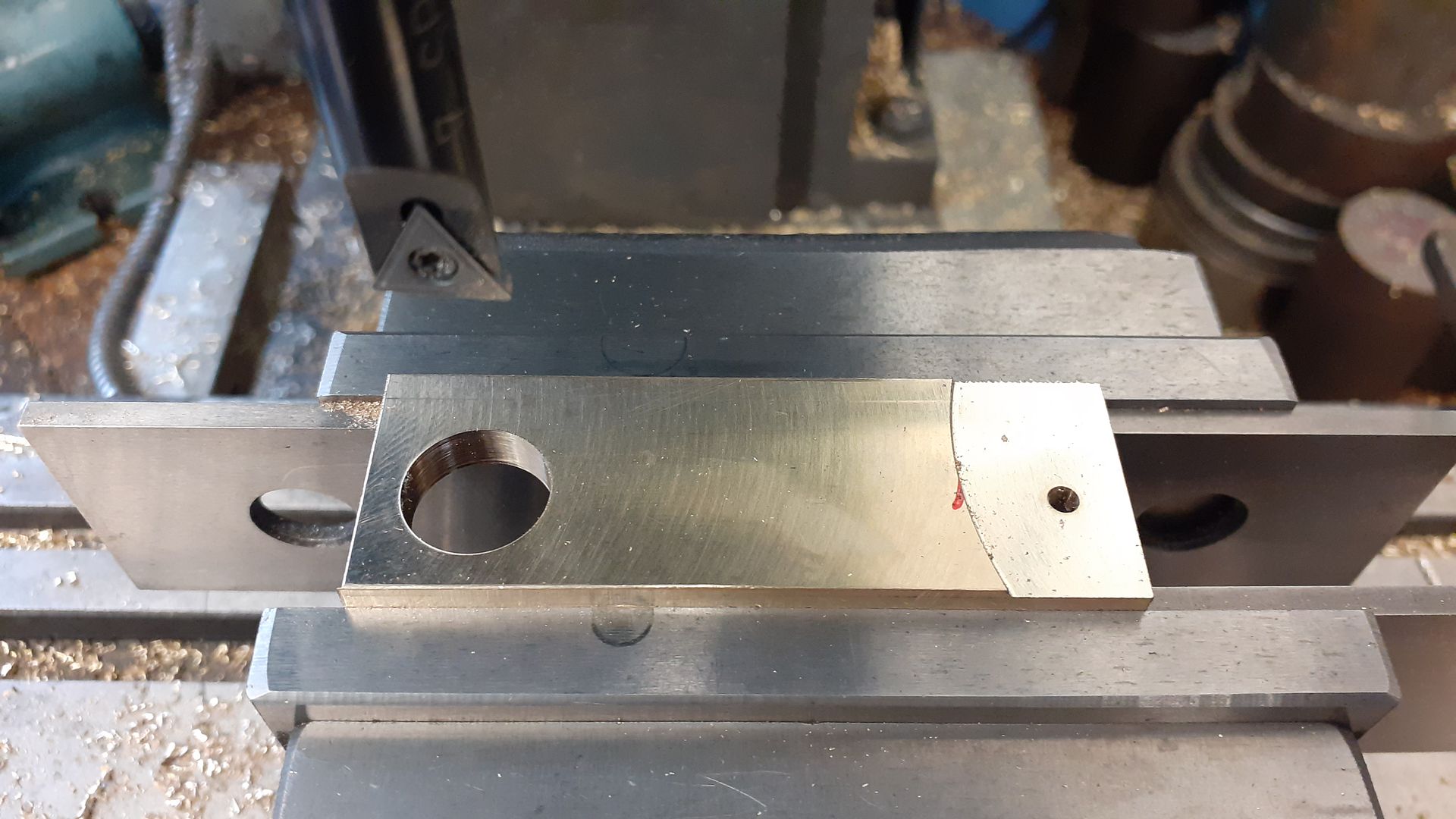
Over to the manual mill and the post face will cut to finished size, 1mm oversize on the other three sides, as there was not much difference between the dimensions I made sure to mark which face was which so I did not get mixed up. I'm using APKT insert sin the 63mm facemill which are meant for aluminium but they work well on all metals and cut a lot smoother in a lightweight hobby mill, it's a similar principal of using **GT insert for fine work in the lathe
I had originally intended to either fabricate the cylinder from bronze (six pieces) or possibly manually cut from iron with not such nice feet but decided to have a go on the CNC, at worse I'd waste a couple of pounds worth of cast iron bar. I used two setups, this shows the one from below which was followed by a similar one from the op down to the half way line but without the feet. The internal fillets are probably a bit large for this size of part but the 4mm ball nosed cutter had the required length as the shank was also 4mm and did not cause any collisions. I could have cleaned up where the flange meets the foot a bit more with two more setups but just filed it as there was so little metal to remove, it's all hidden by cladding anyway.
I use a 6mm cutter with an adaptive path to remove the majority of the material and then a 3D scallop with 0.2mm stepover to do the final shaping which is what you can see here.
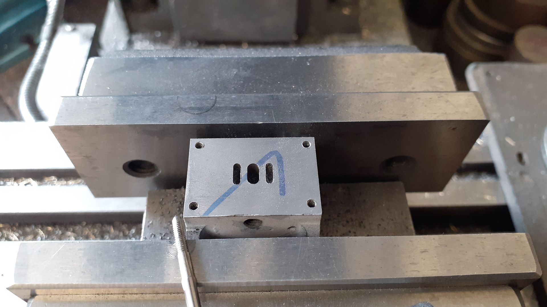
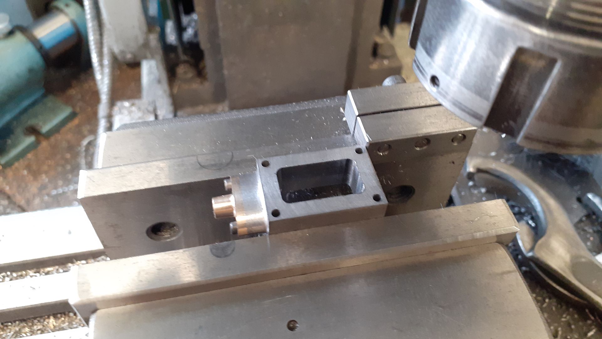
Although I could have done the rest on the CNC I went back to the manual mill to do the steam ports and valve chest stud holes
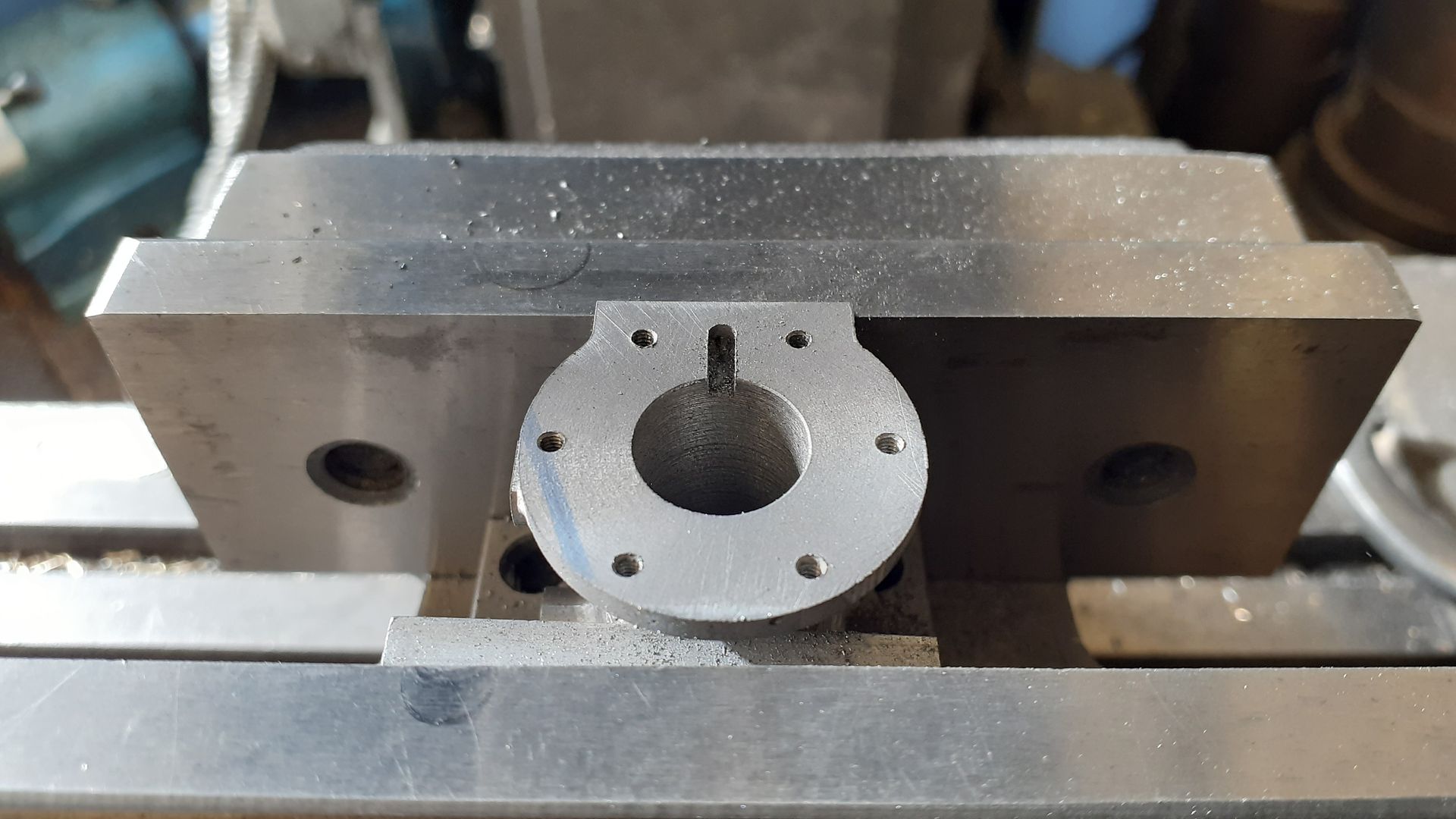
And then the pattern of six stud holes in each end, a hole down to the posts and a slot to link that hole to the cylinder end
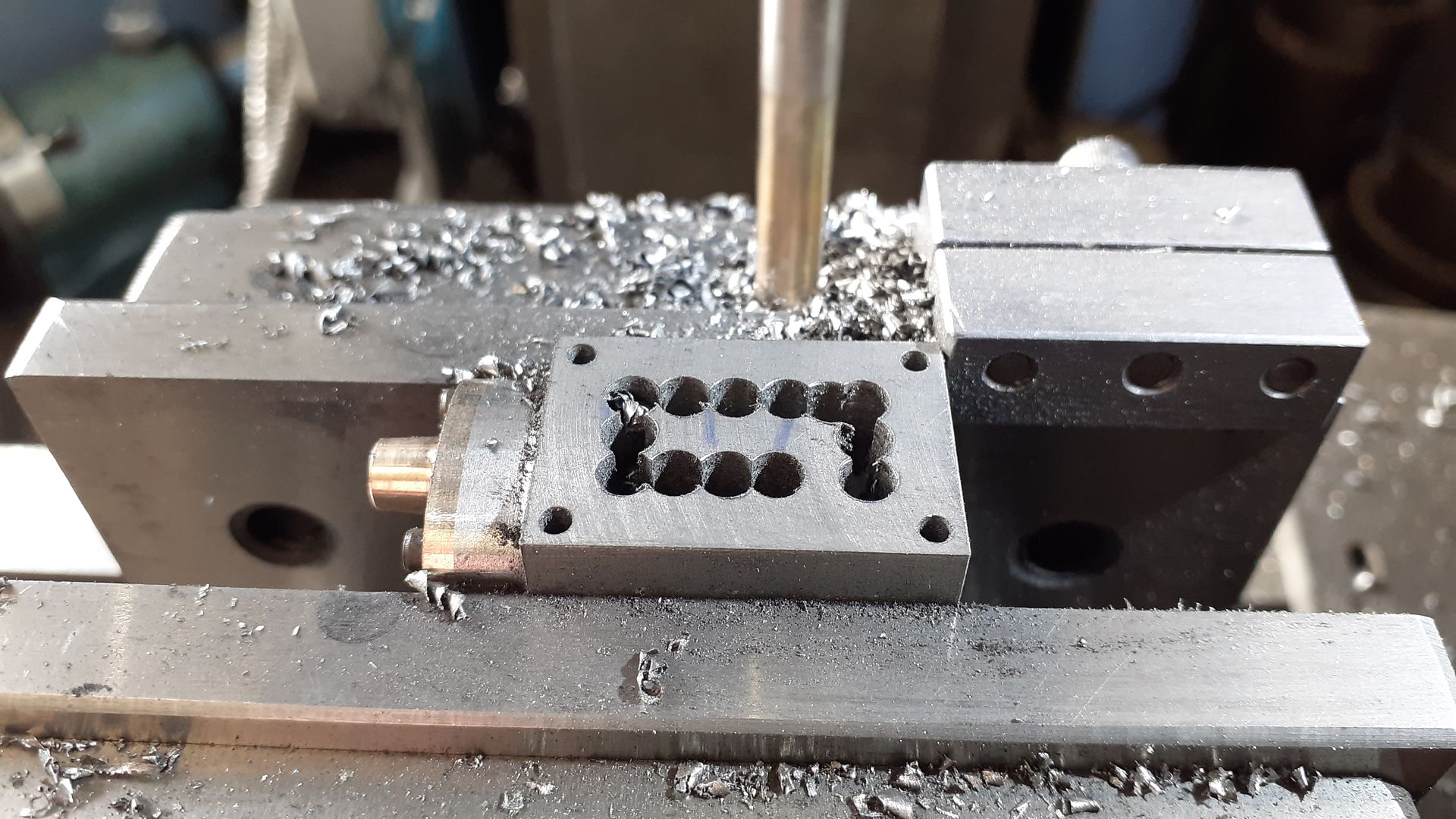
The valve chest had the waste material removed by stitch drilling
And then the internal faces were milled to leave a 4mm wall thickness
One of the tings I use alot , is sacrificial softjaws on the vice. You can create pockets or cut a relief to be like a parallel but with an inbuilt stop etc. Very nice thread and showing how you use both cnc and manual tools to make a really exciting project. A great thread to follow. Thank you very much.
I'm not keen on the "+" shaped reinforcing ribs that Stuarts used on the valve chest cover as they look out of place on a small freelance engine and are not done that well anyway so I opted for an elliptical recess to tie in with the shape of the glands and to keep things similar also turned a round recess in the cylinder end cover rather than the conical protruding one Stuarts used.
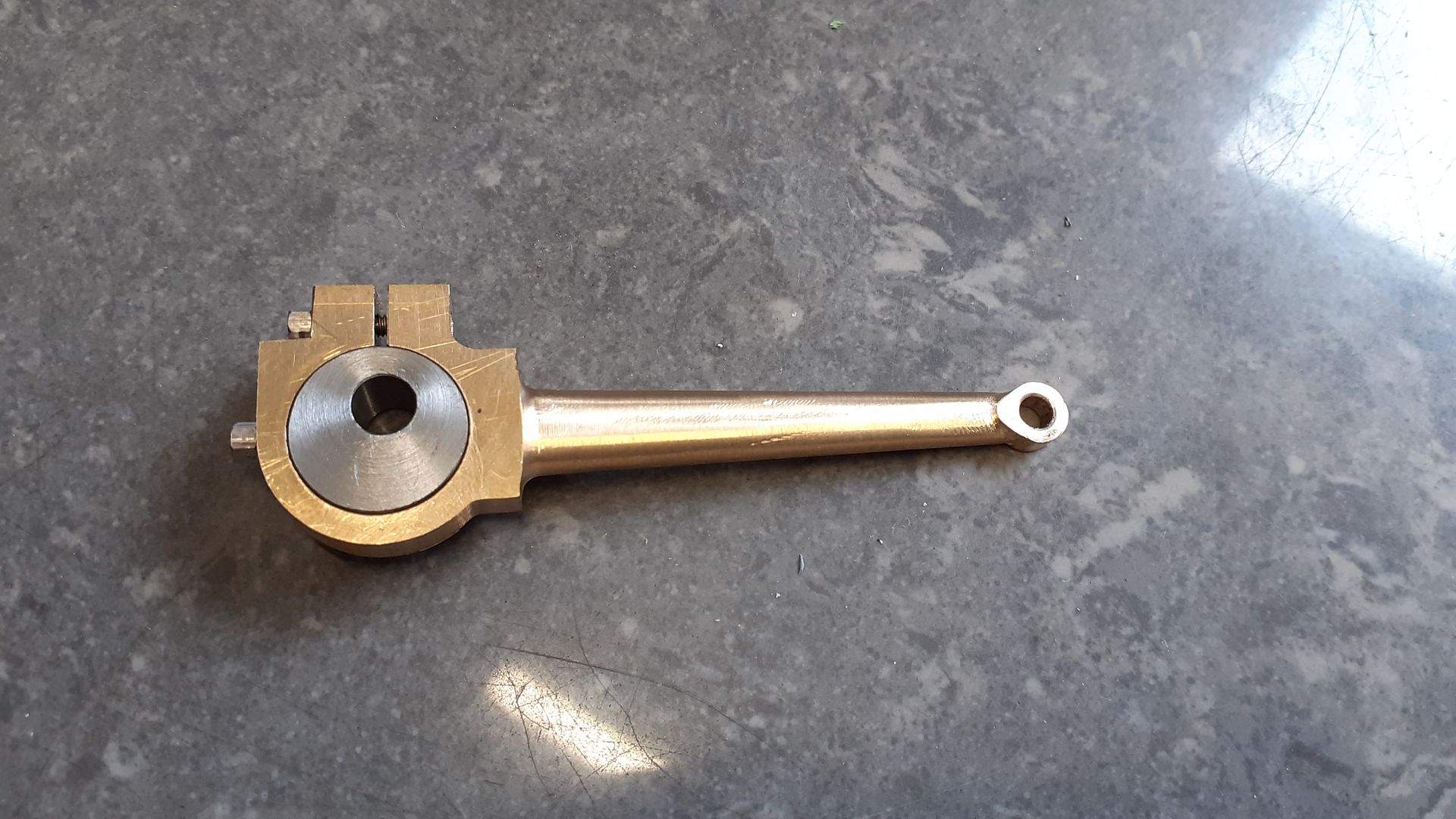
The eccentric strap is shown completely split in two with a pair of bolts holding the two halves together but as it's a simple beginners engine I decided to use a design like that use don the 10 series engines with a single split and pinch bolt which allows some take up for wear if needed. I started out with some brass that was bored (big end) and reamed (small end) as well as thinning the smaller end from 4mm down to 3mm on the manual mill
A couple of top hat bosses allowed the part to be held down while the CNC did it's thing of my usual adaptive path to remove the majority of the waste, two contour passes to finish the outer profile and then a scallop on either side to form the tapered elliptical section of the rod.
The strap could then be used to gauge the size of the eccentric
Which was then offset in a small 4-jaw to be reamed and have the boss turned down to the required diameter
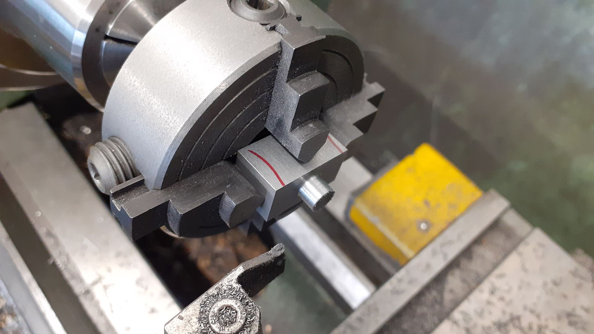
Not being a fan of bright bling on engines rather than use gun metal for the cross head I went with cast iron. After machining up a lump to the required size it was held in the small 4-jaw to Turn the boss on the end
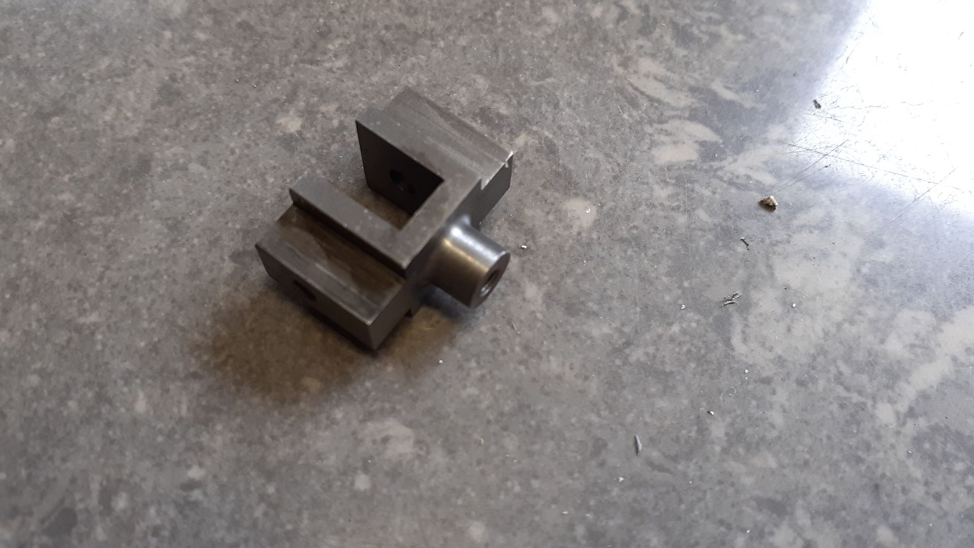
Before milling the various features so it would run in the guide bars and take the end of the conrod
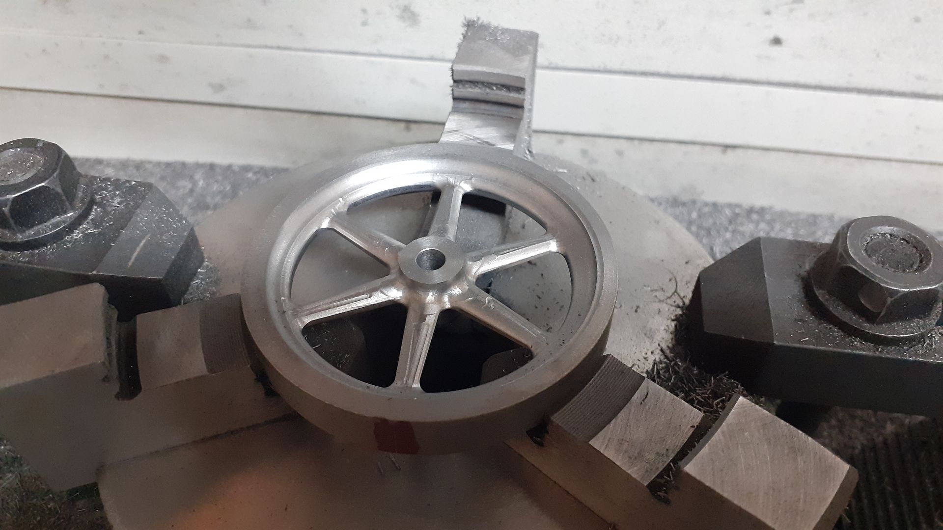
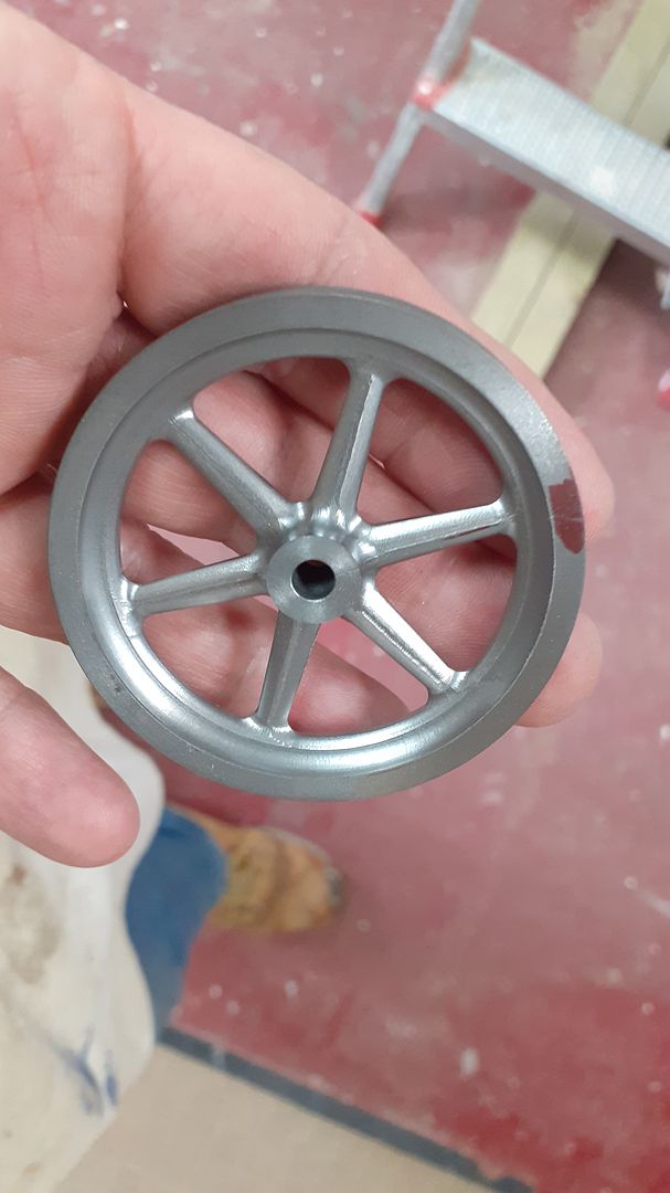
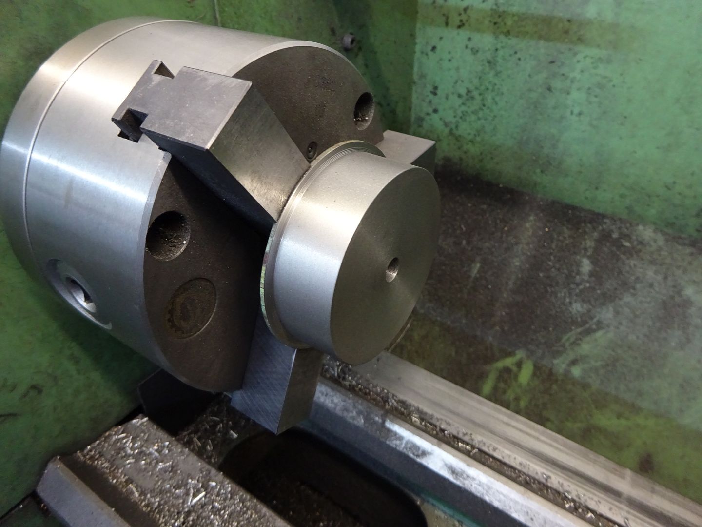
I previously drew up a flywheel and did the CAM for the One-One which used the Progress flywheel so it was just a case of sawing off another bit of bar and CNC machining another flywheel for about 1/10 the cost of a casting.
I did not take any pictures of the various rods, pins and guide rails as they are all fairly straight forward turning jobs so next post we will see what I looks like with a lick of paint.
Neil, I use chuck soft jaws frequently and see Jason has also used them in this build which I feel should be mentioned as well. They are good for ensuring parts are mounted concentric for second operations and also with the machined faces in the correct plane without a lot of checking, adjusting and repeating. They are also good for firm holding without marking the gripped surface. They really save time when there is more than one part with the same diameter to be gripped for second operations.
Jason, I am curious about the soft jaws in the chuck used for milling the ellipses. Were they milled to suit in the mill or just left as they were from when they were on the lathe?
Martin. that is my old lathe chuck that does not get used much on the lathe now and the jaws were done in the lathe.
On both the lathe and mill I tend to use them more for the fact they provide a backstop for shallow work rather than for concentricity and in this case just clocked the part in with a dti in the spindle
This set of jaws have only been machined for approx 35 and 60mm diameters by just over 1mm deep for each and I use them the most as they will hold anything from 25 to 75mm dia quite firmly if you don't go too mad with DOC
I decided to use the same Forrest Green and satin black colour combination that I have used for the other Stuart Replicas which did not take long to apply as there are not that many parts and what's there is all quite small
Once the paint had hardened for a couple of days it was put back together checking the movement was free as each part was added rather than trying to work out where a tight spot is when the whole thing has been assembled.
Quite pleased with how it runs on no more than 5psi of air.
I'm not sure what the next small "replica" will be as I'm running out of subjects to do though I expect something will crop up on the web and catch my eye. Something else ran for the first time this weekend so keep an eye out for details of that though I don't think it will be a build thread.
It took quite a lot of RPM to get it to start walking. And even then it was still quiet and smooth.
And it seems it only took about 3 weeks to build and paint! Amazing.
Just out of curiosity, which particulr vibrations make a model steam engine walk, and is the walk direction different from vertical to horizontal engines? I guess the point of tethering (air/steam line) may also play a role. My guess is the main source of vibration is the piston, but I can see the full answer being quite complicated.
For your next project Jason, is there perhaps a machine that Cherry Hill missed?…only half joking there
Looks like I'm going to have to run it up again and get the tacho out so see what speed it needed to start levitating
I think one reason this one stays fairly well grounde dis that unlike the cast original which would likely have beed hollow I left the base solid which dampend any vibration.
I suppose the counter balanced shape of the crank web is there mostly to counter the in out movement of the conrod, cross head, piston and piston rod but will add some up and down imbalance as the speed goes up. The verticals seem to want to jump about a bit more whether that is due to the moving parts or simply the fact that they have a smaller footprint and tend to be a bit more top heavy I'm not sure.
Build was spread over about 5weeks looking at the dates of the photos, I don't tend to start writing up a build until the engine has been test run. I do tend to have a few projects on the go at once and would have been painting and assembling the James Coombes when I started making this one. And while this has been getting painted I managed to get another engine that has been sitting about for a while completed and test run.
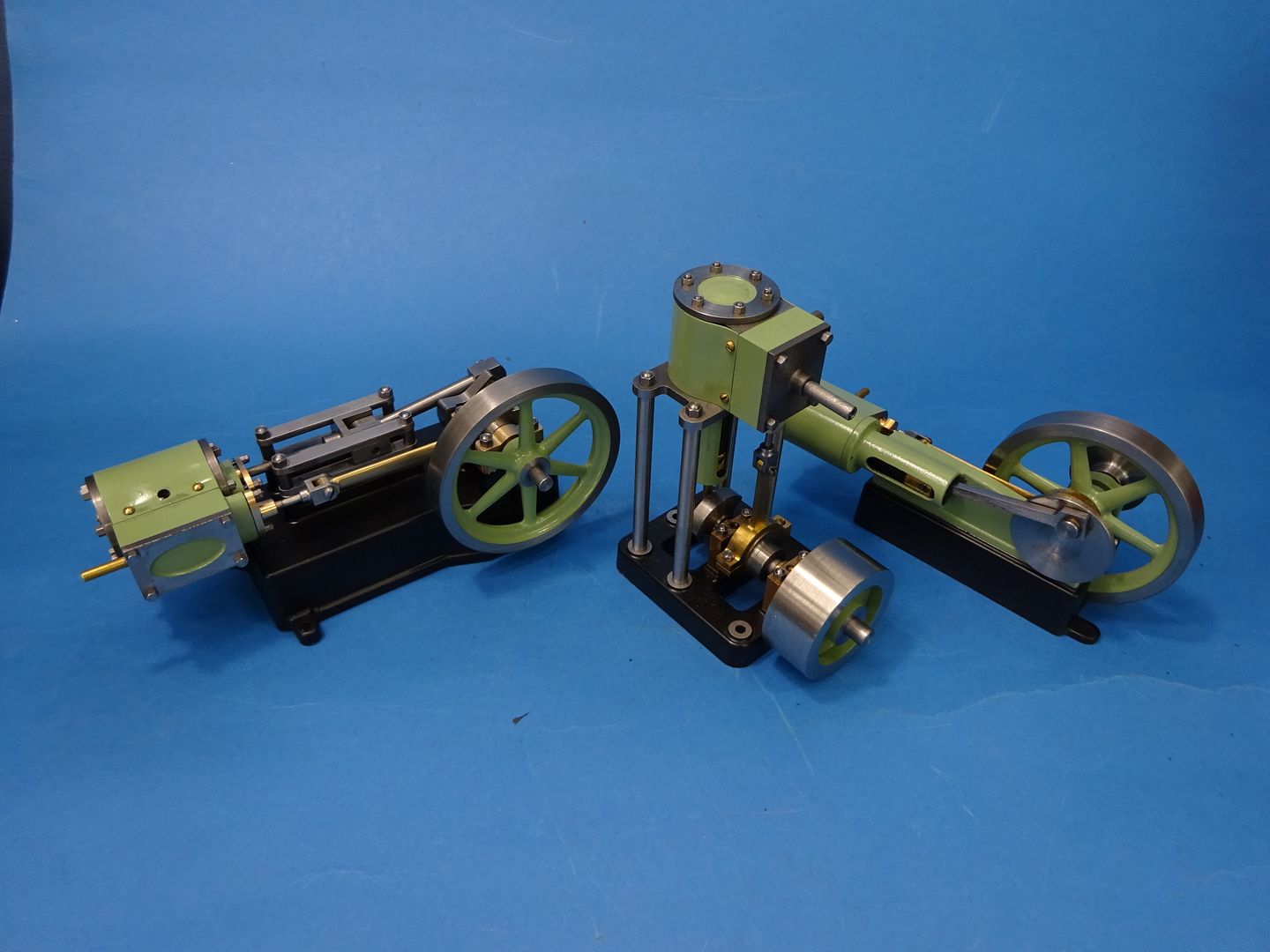
While I was taking the photos of the Progress replica I thought I would take a quick group shot and video of the three Stuart replicas. They have all been quite enjoyable quick builds fitted in between larger projects and are all good runners.
Thanks for the feedback on vibrations and timescales – good stuff.
I wonder if also, sometimes a resonance is found and it all kicks of after that. My 10V seems to be OK up to a point and then it fairly quickly decides it needs a walk after a certain rpm is reached. My Beam stays put in spite of how many rpm I try to throw at it, but that is possibly due to the high mass, which was one of your earlier points.
I wonder if any of the original full sized engines ever suffered from resonances and how they managed that…..adding weights, stiffners etc?
Anyway, a very neat looking threesome that run a treat. Hopefully there is more on the way ie builds plus pics plus CAD info