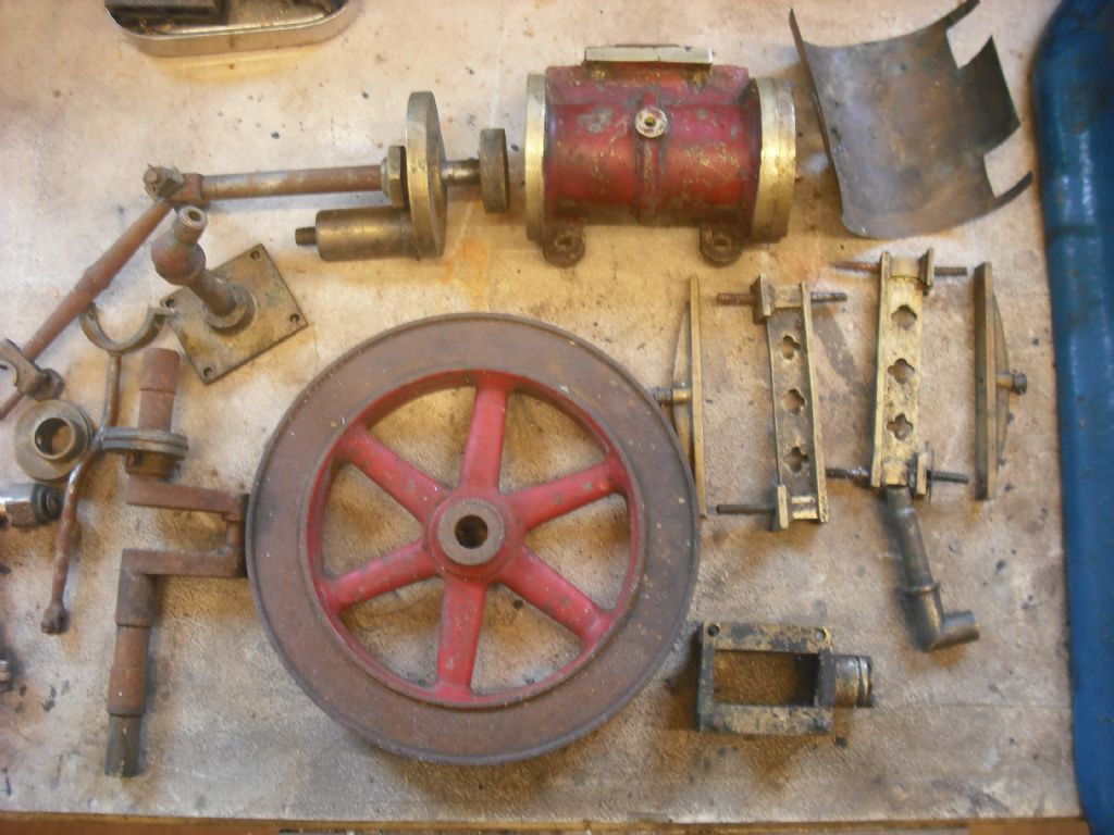
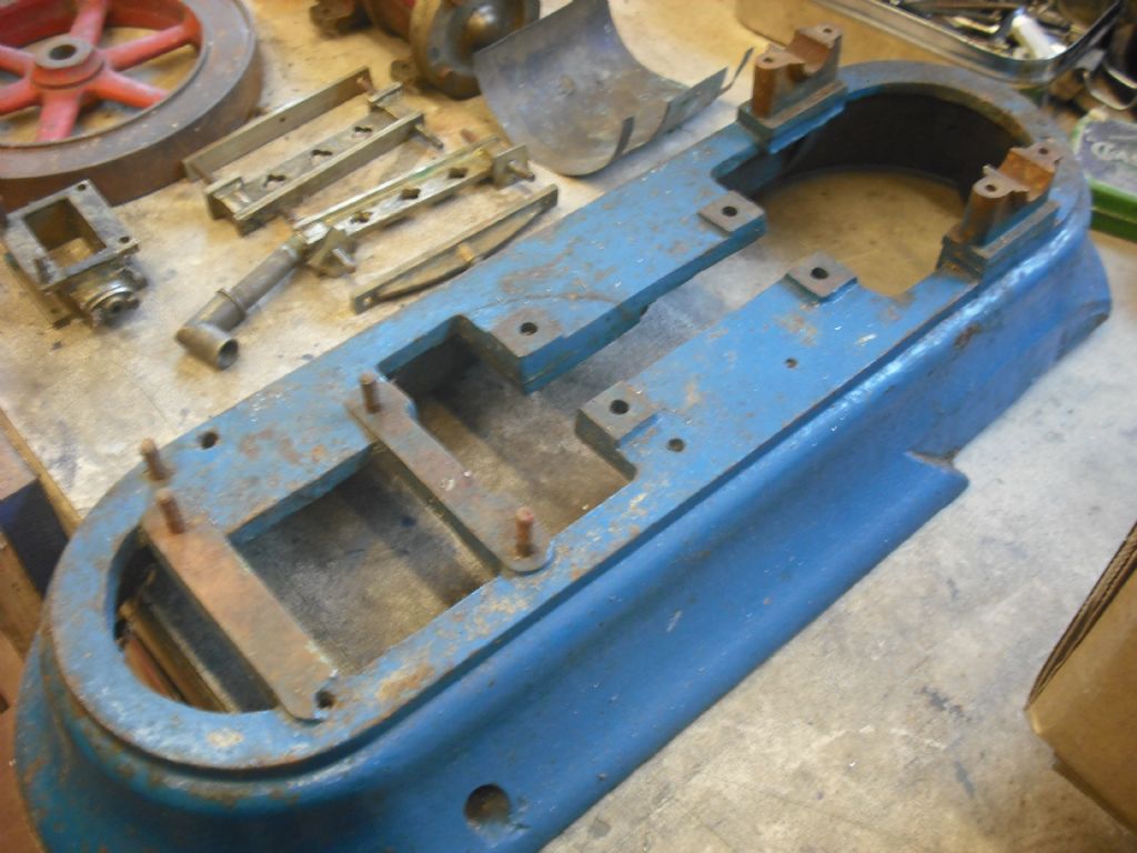
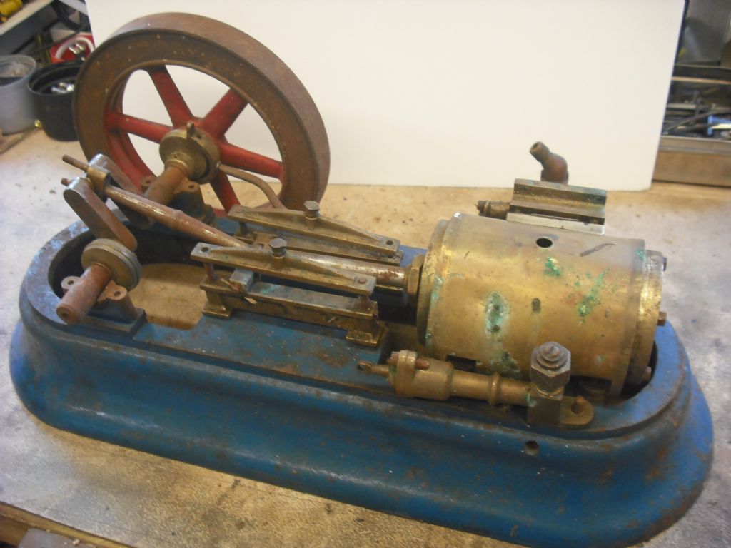
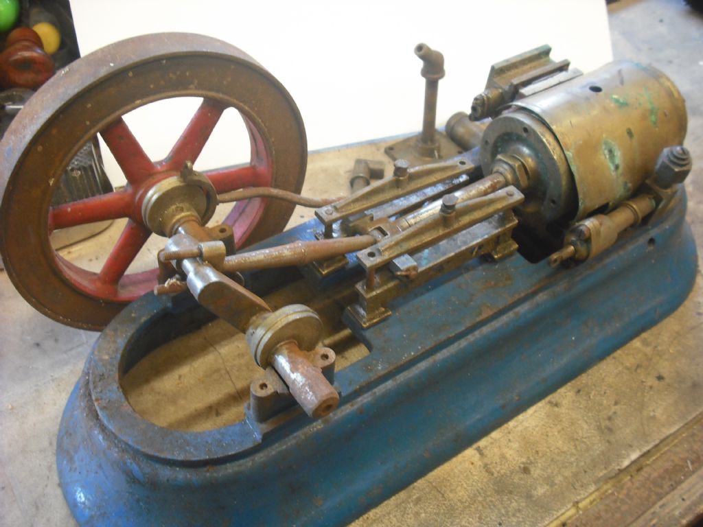
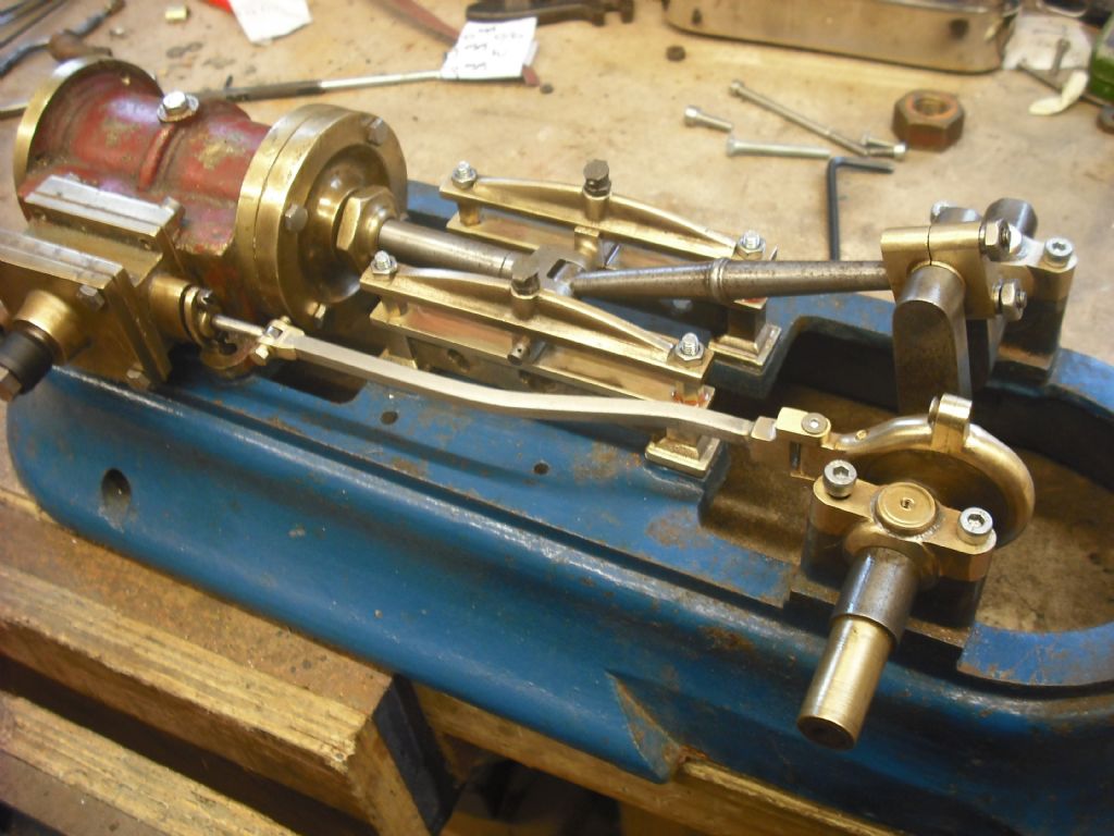
Hi all, I inherited a number of items from an uncle, included was a pretty substantial model mill engine….in bits It is worth noting that I remember seeing this engine running on air when I was a kid. My uncle had a habit of taking things apart and not reassembling them. This is a case in point and, as with the motorbike and the stationary engines I also inherited, there are bits missing.
To list but a few missing parts, crank bearing caps, con rod big-end cap and the slide valve and rod.
The base casting is 450mm long x 170mm wide and the flywheel is 170mm in diameter. There are no casting marks to give a clue to the manufacturer and I have searched all over google images and have not found an engine that looks like it.
Ideally I would like to find drawings for it to save me from having to reinvent things like the slide valve to get the correct lap and lead.
Over 200 views and no one has an idea of where this engine originated it seems, I have spent some time chasing around the internet and still no picture of anything similar.
I have a pretty large collection of taps and dies and can find nothing that matches the threads on everything and as most nuts and bolts are absent and some of the threads are pretty poor I am trying to rebuild it with metric fixings as I have loads of them to hand.
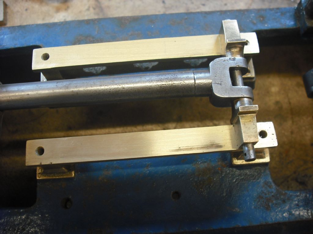
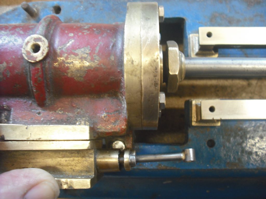
This poor old engine is pretty beat up, the crosshead slides were not parallel to the piston rod so the gland is egged out and the slides were badly worn at one end, I have re-machined the slides and will shim them on assembly.
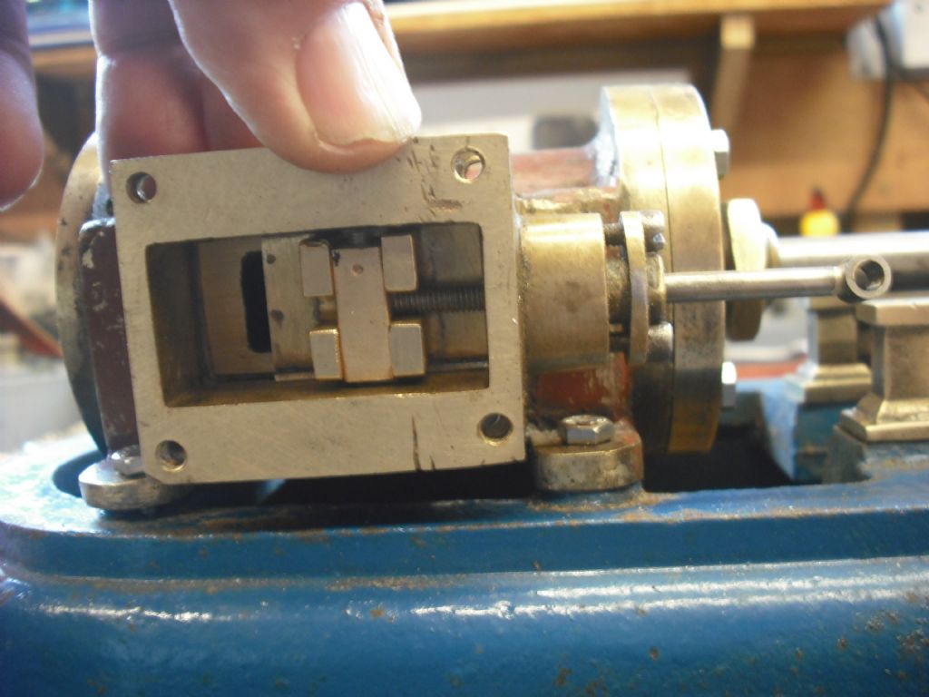
The slide valve face is not parallel with the piston rod when viewed from above. but will be workable, I have made a new valve slide and rod.
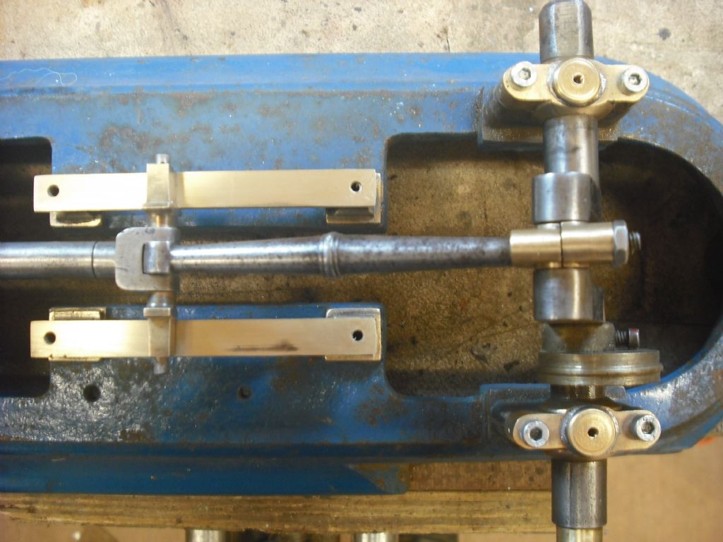
I have made a new cap for the big end of the crank rod and new bearing caps for the crankshaft (the cap screws will be replaced by studs and nuts).
Holes everywhere on the engine are drilled out of line with one they should line up with so making parts has been interesting, the first big end cap I made was scrapped as I needed to drill the fixing holes at an angle to each other to get it to fit.
I am awaiting some gasket paper and metal to make eccentric straps and then on to reassembly.
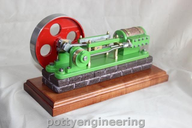
I don't recognise the make, but the design is conventional, a simplification of full-sized engines designed in the 19th century. I think many makers produced them. For example it's similar to Stewart Hart's Pottymill, which is my favourite beginner's engine.
Looks like your engine has two eccentrics, possibly to do forward and reverse, but yours seems to be driving a pump, likely to maintain the vacuum in a condenser. So an up-market working engine in it's day, possibly educational rather than a toy, hence the high-mileage. Probably not an engine that did real work. Though there's space for a belt-pulley, now missing, the engine is a bit small and there's no sign of a governor. However, engines like this were used to charge accumulators for early valve wireless sets before mains electricity was widely available.
That will be a boiler feed pump Dave. Doubt it was used for charging as the mill engine layout is not really conducive to high speed running that was needed for charging
When I first saw it and the size I thought it was more of a "workshop" engine than a model but it is very lightly built in places and things like brass crosshead guides are not that common with steel being the norm and the crosshead slippers are very small with little contact area.
As to that the poor hole positions and it does seem home made, hope you are changing those metric cap heads once the engine is known to run for studs and nuts
There is quite a lot that is unusual on this engine, as stated, brass crosshead slides, it also has brass eccentrics.
The slides could have done with being 1/2" longer, those narrow slippers only just fit between the bolts at each end of the stroke, I will have to make some pretty thin walled slide spacers.
I will be taking the pump apart to see if it has all its gubbins to see if I can get it working