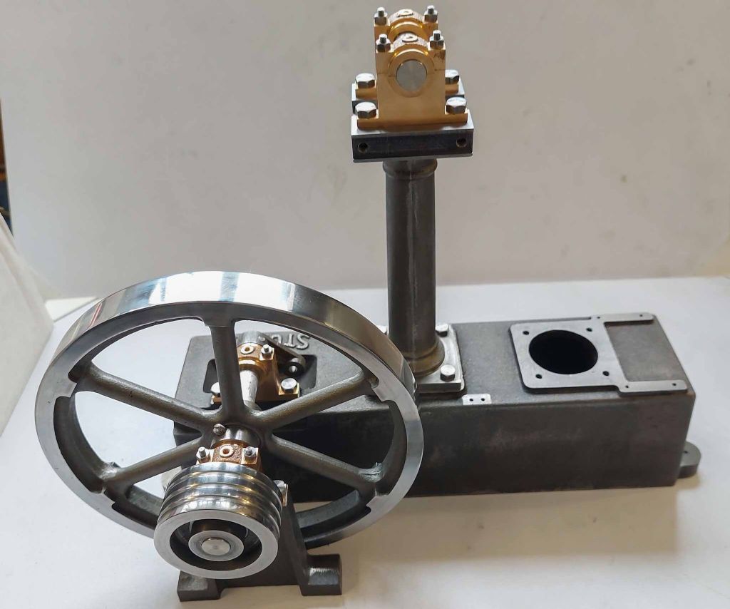
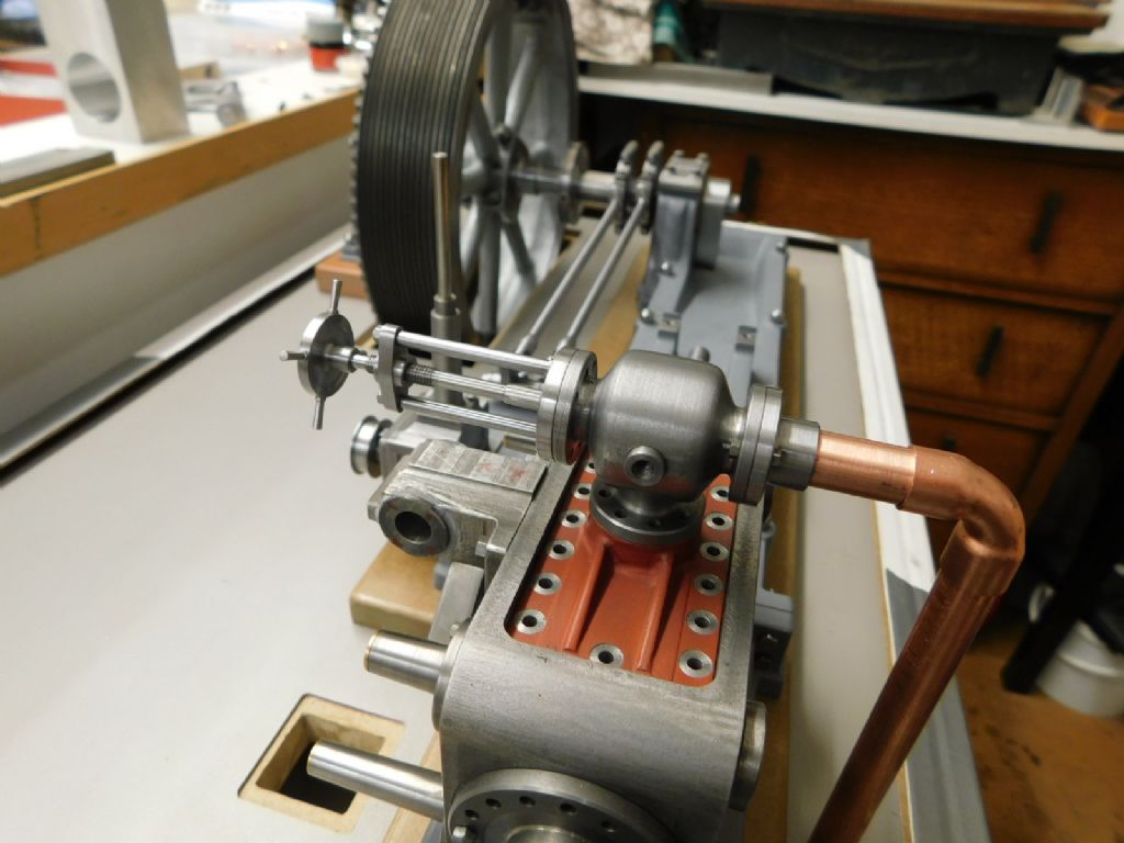
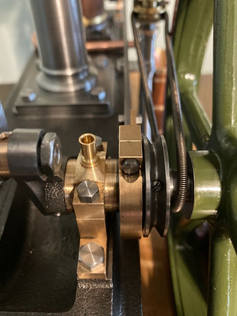
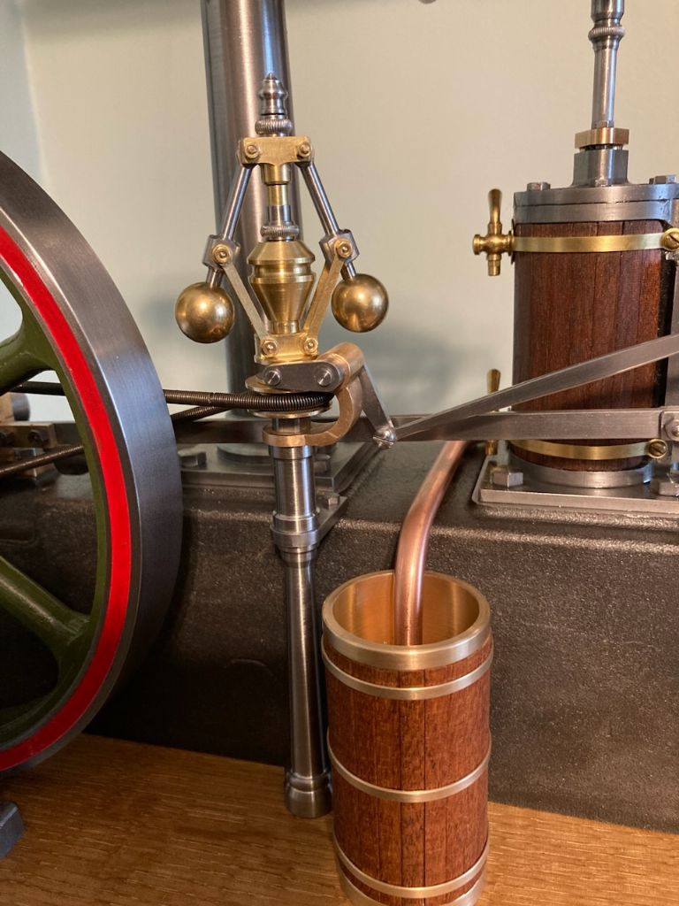
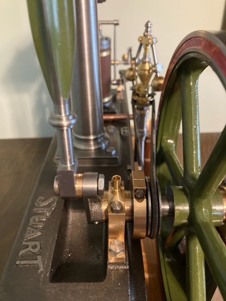
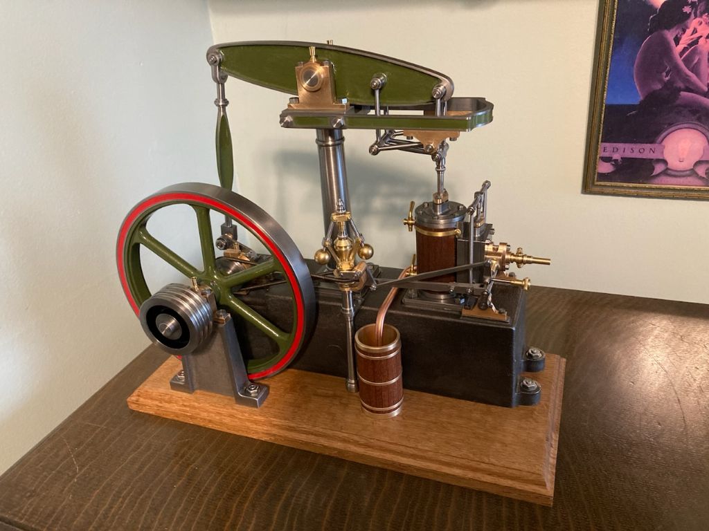
I am working on Stuart Beam engine and Governor casting kits. The picture below is my progress so far.
I have previously made a 10v, the Beam is my 2nd engine so I'm still a novice.
My question is regarding the Governor crankshaft pulley, I'm thinking of making the pulley with double the circumference than the plan says. Just wondering if anyone has any ideas if this will work.?
My reasoning is that I have seen youtube videos of Stuart beam engines running and they seem to run very fast with the Governor fitted. I'm wondering if I make the pulley twice the size and spin the Governor twice as fast the engine will run at half the speed?
Governors do not scale easily. There was an article by Tubal Cain (the English one) in ME a long time ago. I might have a scanned copy, I'll have a look tomorrow
Or you could reduce the air pressure, or steam pressure as the case may be. A small cheap pressure regulator sold at hardware stores for regular air compressors will supply down to a few PSI, on which model engines will chuff over slowly quite happily. If running on steam from a small boiler, a throttling valve right at where the steam leaves the boiler works well. Dries the steam nicely too.
You really only need a governor if the load on the engine is changing. I most cases they just get run for display in which case a low VOLUME of air/steam will slow the engine. Speed like on full size is controlled by regulating the flow not the pressure.
But if built well with no tight spots then you don't need much pressure for display, it's only when the engine needs to work that you need to use higher pressures 5psi should be enough for display and the push fit pneumatic flow valves work well to adjust engine speed.
Running the governor faster will increase it's effectiveness but there are still a lot of losses due to friction in the linkages to overcome and the sprung belts are not the best for transmitting an even drive so best treat the governor as eye candy unless you intend to have varying loads on a working engine.
Also bear in mind that this is a model of a small beam engine not a massive great pumping engine so it would have run faster than what most people think of as a beam engine though you do still get people thrashing them.
Which raises the question: How does time and speed scale on a model? If you build a 1:12 model of a beam engine, should the RPM be 1/12th of the original's RPM? Or should it be 12 times the original RPM?
To which the answer is "It all depends"
In my day job in fluid dynamics, we would build scale models to flow test. Now you can scale flow to give the same Reynolds number as full size, or if it had open surface you could scale to give Froude number as full size. You cannot generally satisfy both without invevting working fluids with impossible properties. Add in that you might also want to scale for Prandtl number, Grashof, Graetz, Mach…..etc.
So it all depends on what you are trying to do. As LBSC summed it up "You cant scale nature"
360 degrees is the same however you scale a subject as it 60seconds so rpm should the the same. In practice the smaller the engine the faster they need to run if doing work.
It's only if the model is moving that distance may want to be scaled that things get complicated.
Regarding the pressure /volume issue, this engine is running on 5psi or less as that is as low as my compressors pressure regulator reads but I'm not altering that to get speeds from 2250rpm down to a tick over, it's the volume of air that I'm adjusting. You don't see a full size or model loco or traction engine letting the boiler pressure drop to almost nothing when they want to run slowly.
Thank you very much for the replies and information.
I'll continue on and see how it goes, I think the standard Stuart design must work OK it just needs some minor changes so the engine runs at a speed that looks OK to my eyes.
Although the input air pressure will have a big effect, I may end up with the Governor working as an on/off switch.
I have seen the Governors working on old Edison phonographs, I realize they are different but they are a very small accurate governor spinning at very high speed so I guess these have affected my thinking and what I expect to see.
Anyway I have just broken my 7BA Tap in the entablature arm so I'm still very novice. I thought I was past stuff like this.
Yes, as LBSC said, you can't scale nature, which would include time. Thinking about it some more, if a full sized engine doing 30rpm is viewed from a far distance so it looks the same size as a model viewed close up, it is still doing 30rpm. So model speed equals full size speed when it comes to rpm.
But linear speed not so much. The rim of the flywheel on the full sized engine will be doing many times the speed in feet per minute than the small model's flywheel rim at the same rpm. And I can't imagine a 5 or 7-1/2" loco doing 60mph and upwards around a typical club track. Its linear speed would seem to be reduced proportionately.
So presumeably, the model loco's axles and wheels could rotate at the same RPM as the full sized prototype, but the wheels being smaller in circumfrence transfer that same RPM into much less linear distance travelled, in the same amount of time. Time being not scalable as per LBSC..
So most videos I have seen of model stationary steam engines whizzing away like crazy on compressed air are in fact way over-revving. They should tick over slowly like the original big 'uns. But, who can resist the temptation to "see how fast she'll go"?
It does depend on the model engine that one I posted the video of was intended for pond boats that were raced from one side of a pond to another so it was intended for speed. You also have the typical Stuart 5A size engines that were used in launches and used ran around 1000rpm, same if they were generating.
On the other hand you have the big pumping engines that I mentioned above that only do a few rpm and that is what people associate with beam engines not the considerably smaller workshop engines that may have run 60-100rpm which is what the Stuart more closely resembles.
……….My reasoning is that I have seen youtube videos of Stuart beam engines running and they seem to run very fast with the Governor fitted. I'm wondering if I make the pulley twice the size and spin the Governor twice as fast the engine will run at half the speed?
Edited By Leon NZ on 28/01/2023 23:20:07
Hello Leon,
In a full size situation the governor is mainly there to keep a constant set RPM – ie the working speed. If the engine for what ever reason speeds up the throttle closes and if a load comes on slowing the engine then the throttle opens up to bring it back to the set RPM
From a model perspective it's difficult – though not impossible – to achieve that but if a model engine is just for display then it's probably best to just ignore the throttle and let the governor follow whatever speed the engine is run at.
Increasing the governor pulley diameter relative to the drive will slow things down but even with a perfect throttle is very unlikely to achieve the result you are after.
I have made three engines with governors – the first, a twin Victoria had a throttles of my own design rather than the butterfly type recommended. These were on each steam chest connected by a common shaft. These were a barrel type similar to an RC carb. The second was on a scaled up Waller engine, again a barrel type and the third on a Corliss engine that controlled the timing of the valve opening.
All worked to a degree, the TwinVic the best of them – if a load was applied to the flywheel the governor would operate the throttles or valve gear but not enough on any to call a 'successful' governor.
The key from a model point of view is 'Throttle' – I'm my view its difficult to make a really effective and efficient throttle – especially the butterfly type – that works smoothly and efficiently relative to the governor speed
It's each to his own of course but a lot of time could be spent trying to make an effective governor set up to run the engine at a constant speed when for the most part it's visual effect that's required. In that case a governor that just goes round at a speed relative to the engine speed is all that's really required.
Regards – Tug
PS For a second engine that looks to be some very nice workmanship – good luck with the rest of the build
Further to my previous post I realised that I did of course make another engine with governor – the M'cOnie. Again I think this was a barrel type but can't really recall.
I've just tried to embed a video of it running but without success. If you take a look Here you can see just how ineffective the governor is.
Another factor to bear in mind is the linkage from the governor to the throttle – it really has to be smooth and of precise movement – you'll see that (despite my assurance that it is free on this model) the governor makes little, if any, effort to move throughout the RPM range the engine is run at.
It's becoming clear the Governor will probably never be very effective as there are so many variables and yes the engine will only be a display model build for the challenge of building not because I have any use for it.
The throttle is another item I need to understand better, it looks wrong to my eyes. Obviously internal combustion engines control speed by regulating the input air, But pneumatic cylinders in industry all have the speed control on the exhaust as it's more effective than the input. The steam engine cylinder is more like a pneumatic cylinder I would have thought. I'm trying to google some more info on this one.
The original engines running on steam had the throttle on the supply line. Steam behaves differently from compressed air in an engine. Biggest difference is the latent heat in the steam that can be used to do work as pressure of the steam drops. From a more practical viewpoint, throttling the exhuast on steam might risk "hydraulicing" the piston in the cylinder with condensed steam that could not escape fast enough. Plus, throttling the supply of steam tended to "wire draw" it as it passed through the small opening in the throttling valve, which tended to help dry the steam out. As it maintained its original temperature (more or less) but left the throttling valve at a lower pressure, it was in fact somewhat superheated.
But for a display model run on air, connecting the governor to throttle the exhaust could be an interesting experiment.
Having picked up a few engines while running on air and accidently .put my finger on the exhaust it is a way to control the speed when running on air.
As Hopper says steam engines regulate the flow going into the cylinder due to the way the steam gives up it's energy as it cools and expands, by restricting the exhaust you will restrict the steams ability to expand to atmospheric pressure.
As you now say it will only be used for display I would set the compressor's pressure regulator quite low say 10psi to start with and reduce further if the engine is free enough. Then control the speed by having a flow valve in the air line which is the most effective way to adjust the speed.
If it were an engine with reversing gear then with those you do have the option of notching up or down which alters the valve opening again changing the VOLUME of air/steam entering the cylinder each stroke.
Here is an example of a simple oscillator of mine, up to 1min10 I am altering the speed by use of the reverser to cut off the air getting to the cylinder, after that I'm using a flow regulator. at about 3min50 you can see the flow regulator and then the compressor's pressure regulator that remained set to about 10psi for the whole video.
Jason is right in that controlling the exhaust outlet does slow the engine but why not do it at the correct point – at the inlet
There's a big difference between the 'throttle' operated by the governor and the 'steam inlet' or to be correct the 'Stop Valve'
The governor throttle is usually shown as a simple butterfly valve but the difference in movement relative to the airflow is very small indeed. Most, though not all, full size stationary engines have a stop valve to open the engine to the steam pressure but it's the governor that sets the speed, either via a throttle or by affecting the valve gear opening period. A stop valve is much the easier option to control speed on a model. Relatively easy things to make to be in keeping with the model a bespoke one gives a lot of satisfaction but a commercial ME sized valve is fine.
All engines made so far have a stop valve to control the airflow and speed of the engine irrespective of incoming air/steam pressure.
On the Lang Bridge Double Diagonal engine made, the drawings were the best (model engineering) drawings I'd ever seen or worked from – before or since. Surprisingly there was no governor. A call to the company revealed that this engine, the full size of which is in the Bolton Museum, was never fitted with one. In life it had powered a calico printing press and as such the speed was set by the stop valve opening to suit the speed of the specific print design being printed.
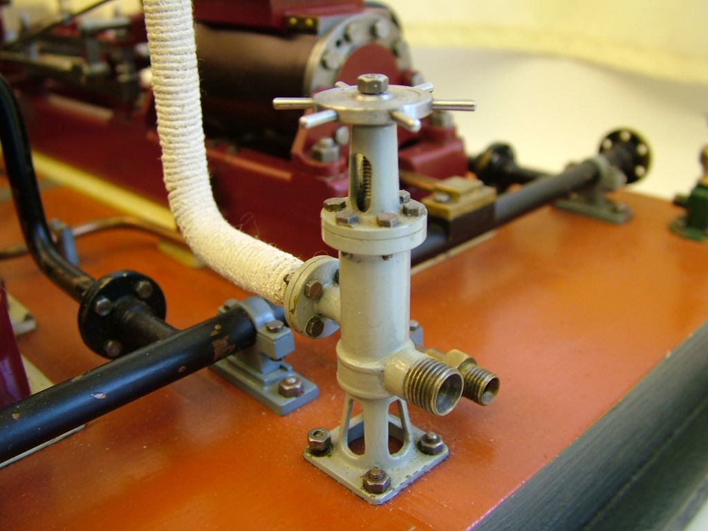
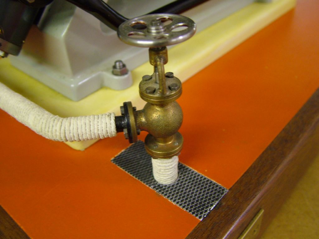
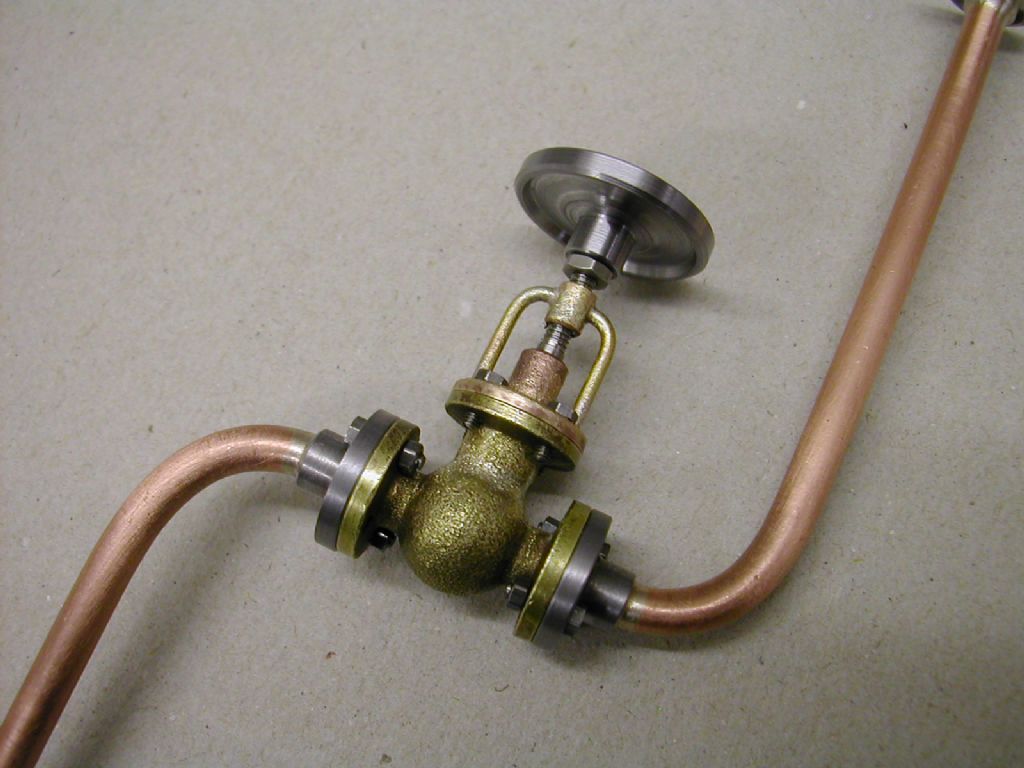
Here are some valves made to suit
The Twin Victoria
The Lang Bridge engine
For the Waller engine
The Corliss engine
Given what you've made so far you should have no issues in designing similar to suit your beam engine.
Your engine is looking great. Regarding the governor, mine begins to do its job at approximately 200 rpm. I used the Stuart ratio which is if I remember correctly, approximately 1.75:1. My governor’s balls are scaled down 20% and I substituted a weight for the spring and made other changes to improve efficiency and hopefully improve the appearance. I prefer to run mine at about 60 rpm, so the governor is not doing anything more than revolving.
One additional note about the Stuart governor. The drawing has you making an eccentric with a grub screw in the center and a separate pulley to drive the governor. This makes valve adjustment a problem because you have to dismantle the eccentric strap to adjust the timing. I simply bored the pulley out large enough to mount it over the cylindrical portion of the eccentric and use a single grub screw that is in the center of the pulley.