Am currently building the Grasshopper Engine from JDW , drawing number EVB-P37.
I have a query on the main beam. The hole at the end for the piston rod is shown as 4.25mm dia, the piston rod fork has a 4mm dia hole through. Has anybody built this engine? Is the 4.25mm a mistake or is it intentional slop?
I know his Muncaster Grasshopper would not run on a 3D CAD simulation as the geometry of the various links caused it to bind up so his "solution" was to enlarge one of the holes but leave the pin smaller. Unfortunately the CAD can't replicate the probably knocking that that "solution" may create.
Could be the same for that simpler grasshopper. You should be able to find plans for Elmers No 37 on the net which is what he based it on. I expect somewhere between his enlarging and converting to metric with some rounding up/down thrown in has caused the problem. Elmer looks to have the fork and beam holes the same as the pins, all being 3/32"
Julius does not build any of the engines he draws so all drawings are untested.
It looks like item 2-09 is designed to have screwed ends of the rod so providing some scope for adjusting the length and geometry. Also you might consider making the pivots at each end with eccentric bushes to provide further adjustment of relative lengths.
A bit of experimentation with drawing pins through cardboard rods and beams would also enable you to settle on teh correct proportions in advance. (or a whole lot of maths)
making it work with slop is likely to wear the piston rod gland in the end.
I think the error is in the beam. Elmer has 2.25" each end from where the horizontal link pivots, link also 2.25". JDW has 86 and 85.5 yet the links are 86. Plus some rounding up /down from the 1.5 times larger scale he has drawn it at. This would tend to want to bend the piston rod towards the crankshaft.
If you have CAD it should be easy to draw it out and simulate the motion.
[…] The hole at the end for the piston rod is shown as 4.25mm dia, the piston rod fork has a 4mm dia hole through. Has anybody built this engine? Is the 4.25mm a mistake or is it intentional slop?
[…]
.
Sounds very much like somebody ‘trying to do the right [draughtsman] thing’ when they were too embarrassed to use the terms bare or full
More like the wrong thing by making the pin a very slack fit to stop the engine binding than tracing the real cause of the binding.
As I said he also did it on the Muncaster when a builder spotted the problem though that builder redrew the mechanisum in CAD so it worked correctly with no slack fits.
Old thread here, don't think I fancy a 6mm pin in a 7mm hole that's taking bare and full a bit far!
I can imagine the frustration and disappointment if a beginner tackles a model engine that appears to look good on a drawing but becomes impossible to run when built.
I realise there will always be the odd drawing error on a published design but I would hope that any designer would have actually built the thing first before publishing his/her design…
I looked at this a bit more and he has also used the 4.25mm hole and a 4mm pin on part 03 which is the fixed pivot for the two links so a second item that will knock and the combined total of the two will give the missing 0.5mm from the length of the beam.
Geoff, how many parts have you made so far? Changing the beam looks the best option but it may also be possible to change the two side links which have less work in them.
If one takes a look at Elmers GA you can see that the vertical line that the piston rod moves in forms the base of an isosceles triange( two equal sides) with one of the longer sides being the link and the other the end of the beam to the hole where the link fits. As the piston rod goes up and down the base of the triangle will alter and as the two other sides are equal all will move a sit should. On Julius's one you will reach a point where the whole thing locks up as his will form a scalene triangle ( all three sides different length)
And for Michael's further enjoyment Elmer notes the holes in the beam and the pins with a circled "C" next to their diameter for "close fit"
I am currently doing a 3D CAD model of Elmer's wooden grasshopper (Number 10) as I want to make one at some point for one of my grandsons. As I go I am changing it to metric and making clearer layouts for manufacturing. What happens when doing one of these exercises is that as you change one dimension it can have a knock on effect on everything else. So you end up going back over previous parts to tweak positions of pivots and distances between them. I have got to the point where the crank pin throw has been calculated and after that it will be doing a similar exercise for the eccentric. I can understand how easy it must have been for people not working with CAD to introduce small errors. Once those small errors are on paper and the parts made it is probably too easy to think there is an error in manufacturing and so modify parts to ease the working of the engine.
I can understand how easy it must have been for people not working with CAD to introduce small errors.
Martin C
But Julius uses Solidworks and no doubt spotted the locked up linkages but chose to make the pivots a sloppy fit so it would move rather than sort out the error by simple geometry. I don't think even Solid works can simulate the knocking and wear as the pins move from one side of the hole to the other
I looked at this a bit more and he has also used the 4.25mm hole and a 4mm pin on part 03 which is the fixed pivot for the two links so a second item that will knock and the combined total of the two will give the missing 0.5mm from the length of the beam.
Geoff, how many parts have you made so far? Changing the beam looks the best option but it may also be possible to change the two side links which have less work in them.
If one takes a look at Elmers GA you can see that the vertical line that the piston rod moves in forms the base of an isosceles triange( two equal sides) with one of the longer sides being the link and the other the end of the beam to the hole where the link fits. As the piston rod goes up and down the base of the triangle will alter and as the two other sides are equal all will move a sit should. On Julius's one you will reach a point where the whole thing locks up as his will form a scalene triangle ( all three sides different length)
And for Michael's further enjoyment Elmer notes the holes in the beam and the pins with a circled "C" next to their diameter for "close fit"
Edited By JasonB on 16/10/2022 08:03:07
Jason's explanation only works if the connection to the main beam is exactly half way along. You can make it work (not quite as well) with the connection not at half way, but then the fixed point of the short link is not on the piston rod centreline. I'll work out the general relationship if anyone is interested.
It can work anywhere along provided the link Ctr to Ctr is the same as the distance from end of beam to where the link attaches to the beam as it will still have two equal sides to the triangle.
Interested to see how your thoughts work out Duncan
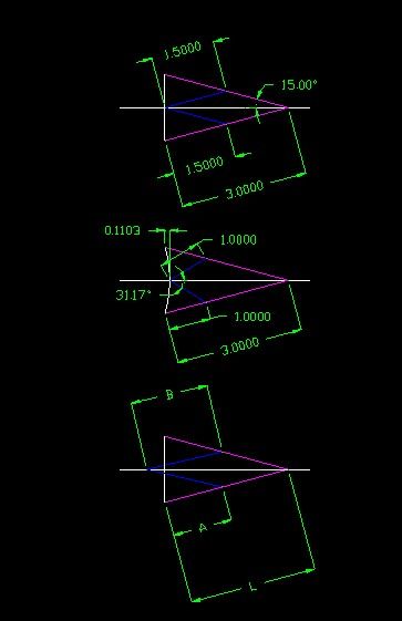
The top picture has the connection to the beam (cyan) at half way position, and the correcting link (blue) equal to half the beam length, The right hand end of the beam is constrained to move in a straight horizontal line. The left end of the beam where the piston rod connects moves in a dead straight line. In the second picture I've moved the connection to the beam to 2/3 the way along the beam, and made the correcting link 1/3 of the beam length. The angle of the correctig link to horizontal is now 31 degrees, and the left hand end of the main beam now moves in a shallow arc. With the beam going 15 degrees up and down, the error is 0.1103. If the beam were just anchored at its right hand end, the error would be 3(1-cos(15))=0.1022, so this is not a good linkage. The third picture shows a linkage with the anchor point for the left hand end of the correcting link moved off the piston centre line. The text book relationship is B=(L-A)^2/A. If I plug in L=3, A=1.4 I get B=1.829, and the right hand end of the beam moves in a very shallow arc, the error being 0.0002 according to the CAD, which isn't bad.
By playing tunes with the link lengths, you can get it to generate a long radius arc, which could be of use in some applications.
This linkage is attributed to Scott Russell. I'm not sure whether this is the same chap who constructed the Great Eastern. It forms the basis of Joy's valve gear
It gets more interesting when you add the vertical link on the right which is often a ladder or cross braced part.
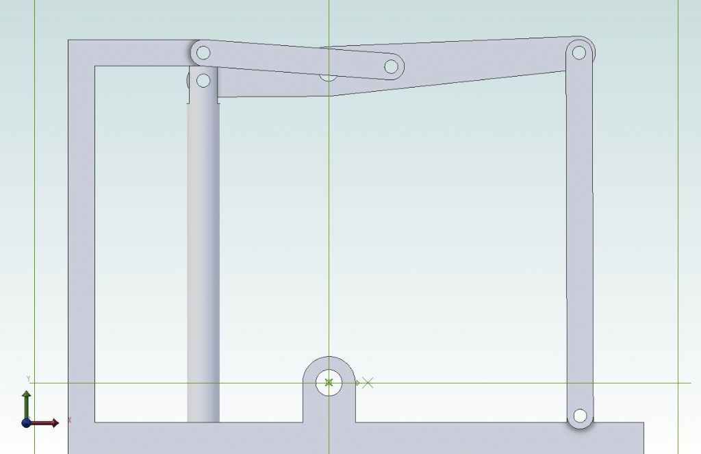
As the top hole in this vertical link moves in an arc there is a small amount of vertical movement where as the half/half proportion wants the right hand end of the beam to move horizontally.
Alibre seems to allow it to only move a certain amount, this is about the maximum it will go above or below horizontal.
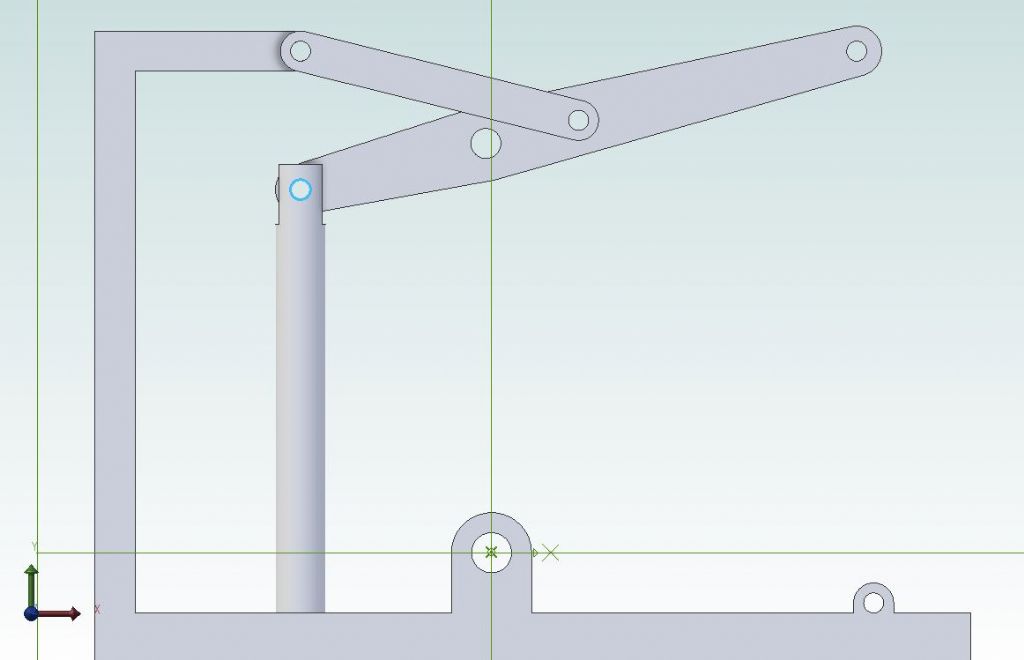
If that link is removes the beam can go to whatever angle you line and the right hand ends still remains at the same horizontal height.
I looked at the geometry of Elmer's wooden grasshopper right hand pivot as it is clearly constrained by the leg to travel in an arc but horizontally by the linkage. It works out from the original dimensions that the horizontal pivot movement is ±0.032" and since the arc has a radius of 5.125" this results in a vertical error of 0.0001" or ±0.00005" . I don't think I need to worry about this slight error in the motion locking everything up since I am also intending to make the pivot bearings out of some Oilon (Nylon 6 sheet with added oil) I have in my scraps collection which will add a little bit of give into the mechanism.
I found similar playing with the #37 grasshopper some more, if I added a couple of microns tolerance to the beam/vertical link joint then it could be fully animated so allowing for the clearance that would be needed in all the pivots there should not be a problem if link is half beam distance.
As Jason has found, if you attach the right hand end of the beam to a vertical link and constrain the left hand end to go in a straight vertical line it locks up. If we take the vertical link to be 3 long, and the other dimensions as my previous post, the top of the vertical link moves back and to by 0.1022. If we get a bit clever and move the fixed bottom pivot across to the left by half of this, the vertical link will swing plus and minus asin(0.1022/2/2)=0.98 degrees. The top of the vertical link will now be in the right position at top middle and bottom of the stroke, in between it will be too high by 3*(1-cos(0.98))=0.00044, and the left hand end will describe a very shallow S shape. I could work out how much it deviates from a straight line, but it's a lot more difficult than what has gone before, so I'm not going to. If you make the vertical link too short it might start to become significant, but all the full size grasshoppers I've seen had long vertical links.