Horn Antenna for Radio Astronomy

Advert

Horn Antenna for Radio Astronomy

Home Forums Related Hobbies including Vehicle Restoration Horn Antenna for Radio Astronomy

Viewing 20 posts - 1 through 20 (of 20 total)
  • Author
    Posts
  • #34399
    Clive B
    Participant
      @cliveb55652
      Advert
      #383303
      Clive B
      Participant
        @cliveb55652

        Hi folks,

        This project made an interesting diversion form my Stuart Beam engine. There seem to be people on this forum who are interested in astronomy so I thought I'd post this. It was made for my brother in law who is a keen astronomer and is just getting started in radio astronomy.

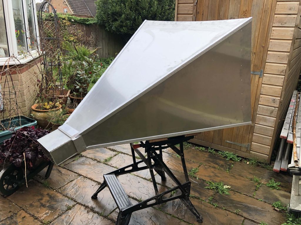
        It's a pyramidal horn antenna designed to operate at a wavelength of 21cm (1.42GHz) which is the hydrogen HI line **LINK**. The dimensions are quite large for a horn at 940 x 735mm aperture and approx 1.4m length including feed. This gives a theoretical gain of 20dB.

        antenna 1.jpg

        Because I don't have the skills or equipment for welding, the whole thing is bolted together. Some might be wondering why there are so many bolts; they are spaced at 1/10 wavelength to ensure good electrical continuity at the frequencies of operation. There were no particularly difficult parts apart from cutting some reasonably accurate tapers on the mill – these are for the transition pieces between the waveguide feed and the flared horn section – first time I used a sine bar. The large flared plated were cut at reasonable cost by Model Engineers Laser. The design for the mount is still being worked up.

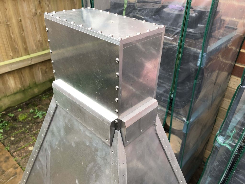
        The following picture shows the waveguide feed section and transition section:-

        antenna 2.jpg

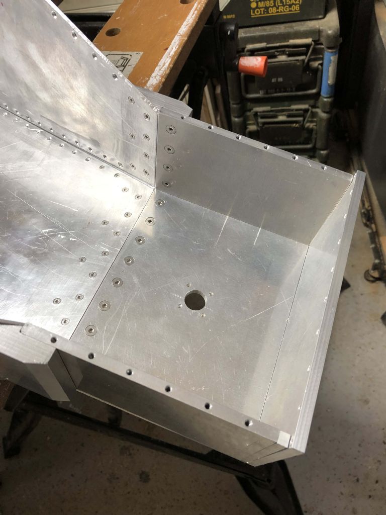
        This shows the method of construction internally and the fixing/feed point for the coax connector:-

        antenna 3.jpg

        Hope this was of interest,

        Clive

        #383308
        Former Member
        Participant
          @formermember19781

          [This posting has been removed]

          #383320
          SillyOldDuffer
          Moderator
            @sillyoldduffer

            Very smart!

            This is the famous Holmden Horn in New Jersey that promoted the Big Bang to Theory status:

            Story is the two guys experimenting with it were baffled by the unexplained noise it picked up and were slow to admit it really was cosmic evidence. Their efforts to eliminate the noise included climbing inside to clean out a gigantic quantity of pigeon poo. It seems Horn Antennas are the avian equivalent of a public toilet…

            This is the fate of all engineering.

            smiley

            Dave

            Edited By SillyOldDuffer on 02/12/2018 12:12:33

            #383324
            Neil Wyatt
            Moderator
              @neilwyatt

              Excellent, Clive.

              Keep us up to date with how you get on.

              Neil

              #383327
              Joseph Noci 1
              Participant
                @josephnoci1

                Nice Horn that Clive! Have you an idea of the weight?

                I must admit I would have thought a Parabolic dish antenna would be far easier to mount, manipulate and set up.

                I realise you are not into antenna – Is your brother in law an antenna guru?

                A 1 meter diameter dish ( almost the same frontal area as the horn) of F/D ratio around 0.4 ( typical of most small TVRO dishes), fed with a very easy to make patch antenna or better still a 2 to 3 turn helical antenna ( even easier to make) will give an antenna of around 65 to 70% efficiency, and gain of 21 to 23dB. If using the helical feed it has the advantage of only 3dB signal loss for cross polarised signals, very typical of the hydrogen HI line radiation oft rapid polarisation oscillation. The horn would give 3dB more gain if aligned with the signal polarisation, and 'no-gain' if cross polarised.

                The dish would be much lighter and not require polarisation rotation if fed with the helical. Wind loading would be a little more, maybe 20% or so, front on, and probably less side on.

                All those screws….! My Goodness.

                I think welding on that size may cause some distortion, but even 5mm distortion would affect the gain by no more than 1 to 1.5dB at worst.

                Do you have photos of the curved transition pieces? Those are the trick in the matching..

                Regards

                Joe

                Edited By Joseph Noci 1 on 02/12/2018 12:40:31

                #383330
                John Haine
                Participant
                  @johnhaine32865

                  You will need to watch out for the joints getting corroded where there are currents flowing across them. This can seriously affect the waveguide loss.

                  #383556
                  Clive B
                  Participant
                    @cliveb55652

                    Thanks for the kind words everyone.

                    Joe, The horn was supposed to be a simple solution, although it is a bit unwieldy at 15kg! In the longer term, particularly for gains higher than 20dB, agreed the dish would be a better way forward but I believe the feed needs some care. The transition pieces are shown in the third figure.

                    Cheers,

                    Clive

                    #383591
                    jason udall
                    Participant
                      @jasonudall57142

                      Looks about the same size as a J band one I built at uni.
                      Of course at J band even though simular size much bigger in wave lengths (J band is 15 to 30 mm ) and from memory Large end was 800 mm..again from memory output was 15 mm widest so area ratio 2800 gain of around 28dB measured mid band..
                      Learn to weld brass for this..using beautiful Oxy hydrogen torch..

                      Edited By jason udall on 03/12/2018 19:06:45

                      #383604
                      Joseph Noci 1
                      Participant
                        @josephnoci1

                        Hi Clive,

                        Yep, 15kg is a 'bit' unwieldy! A 2 turn helical feed for a dish of between 0.3 to 0.5 F/D is very easy to do and to match. It becomes difficult when the dish is very deep and the feed gets closer to the rim of the dish – the feed cannot easily illuminate the full dish sides so the efficiency drops.

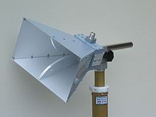
                        I still am not sure what the transition pieces are – When you mention by that name, it normally means the curved tapered transition plates as in the photo below, seen from the open end. Those plates extend the horn matching bandwidth to a decade or more, and I was wondering why such a wide frequency bandwidth was needed when the interest was only in the HI line frequency – since those are not the plates you mean the horn is indeed narrow band – matched mainly only at the resonant frequency of the coax feed element at the horn focus.

                        I am interested to see how the horn performs, and what the cross polarisation effects show up as.

                        Still an engineering masterpiece!

                        Joe

                        pyramidal horn.jpg

                        #383628
                        Neil Wyatt
                        Moderator
                          @neilwyatt

                          Dave,

                          You may be interested in this discussion on another forum:

                          stargazerslounge.com/topic/319651-anyone-doing-hydrogen-line-observing/?tab=comments#comment-3496121

                          An interesting project would be to see if you can measure the doppler shifts of the galactic arms.

                          @Joe, I think you need huge receivers to detect the faint polarisation modes of the cosmic microwave background.

                          Neil

                          #383633
                          Clive B
                          Participant
                            @cliveb55652

                            Hi Joe,

                            I think your picture shows a double ridged horn which is optimised for a much wider bandwidth. Here is where my knowledge of antennas becomes extremely flaky however. The pyramidal horn I described is fed from rectangular waveguide (WG650 size in this case) which limits the bandwidth to approx. 1.15-1.72GHz. It is a very conventional design. The transition plates as I call them just connect the rectangular waveguide feed to the flared plates where the angle changes and there is no gradual flare. They serve a very different purpose to the tapered "ridges" shown in your picture, there are no "ridges" in the horn that I described.

                            Clive

                            #383652
                            SillyOldDuffer
                            Moderator
                              @sillyoldduffer
                              Posted by Neil Wyatt on 03/12/2018 20:19:55:

                              Dave,

                              You may be interested in this discussion on another forum:

                              stargazerslounge.com/topic/319651-anyone-doing-hydrogen-line-observing/?tab=comments#comment-3496121

                              An interesting project would be to see if you can measure the doppler shifts of the galactic arms.

                              Neil

                              That is interesting specially considering the problems I'm having at the moment at the other end of the spectrum using a wire antenna consisting of 15m of wire in my loft and 12m out the window across my back garden, about 8m high. Despite the antenna being carp 200mW of WSPR on 3570kHz was received 2700km away in the Canary Islands, and by k9AN in Illinois on 7040kHz at 6300km. I'm trying to analyse the data to see if I can calculate the height of the reflecting layers in the ionosphere.

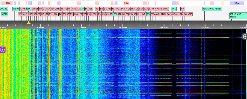
                              Much less success receiving. This is my new toy, a KiwiSDR, which can see from 10kHz to 30MHz in one go.

                              interf.jpg

                              The waterfall display shows heavy interference and no obvious stations. On the left the Long Wave is full of hash from switch mode power supplies and energy saving lights. I think the Medium Wave is hidden under ADSL internet noise radiated from telephone lines. Shortwave up to about 18MHz looks to be awash with VDSL noise also off phone lines. The bright horizontal lines slashing across the screen are caused by my Ethernet over Powerline equipment.

                              Partly my own fault – I bought a house that's almost surrounded by pole strung telephone and power cables.

                              Lot to be said for pointing a beam into the sky – I might be able to hear something! As to detecting doppler shift from the arms of a galaxy, I've no idea how big the effect would be or how long it would take to measure it? I'd need to make a long yagi and a motorised equatorial mount to keep it on target. The radio and data analysis part I think is fairly straightforward. Ten years ago technology would have been special: today it's almost too easy.

                              Thanks for the link – another fascinating distraction!

                              Dave

                              #383737
                              duncan webster 1
                              Participant
                                @duncanwebster1

                                To add a note of levity, if the OP makes second horn he could then make an acoustic radar set

                                see**LINK**

                                #383747
                                Swarf, Mostly!
                                Participant
                                  @swarfmostly
                                  Posted by SillyOldDuffer on 02/12/2018 12:12:15:

                                  Very smart!

                                  This is the famous Holmden Horn in New Jersey that promoted the Big Bang to Theory status:

                                  Story is the two guys experimenting with it were baffled by the unexplained noise it picked up and were slow to admit it really was cosmic evidence. Their efforts to eliminate the noise included climbing inside to clean out a gigantic quantity of pigeon poo. It seems Horn Antennas are the avian equivalent of a public toilet…

                                  This is the fate of all engineering.

                                  smiley

                                  Dave

                                  Edited By SillyOldDuffer on 02/12/2018 12:12:33

                                  This episode is described in one of John Gribbin's excellent books – I recommend them.

                                  I believe that the functional heart of the so-called ' Holmden Horn' is actually a segment of a paraboloid. That's the base of the 'scoop' on the extreme right-hand end of the structure. The focus is somewhere just inside the hut.

                                  Modern satellite TV antennae have the same basic layout but don't have the enclosing pyramid (or the hut! ).

                                  As I'm not an antenna guru, it isn't clear to me whether the Holmden pyramid is part of the feed to the paraboloid or a purely mechanical structure to hold the paraboloidal segment and the feed in the correct spacial relationship.

                                  Best regards,

                                  Swarf, Mostly!

                                  Edited By Swarf, Mostly! on 04/12/2018 12:53:22

                                  #383753
                                  Neil Wyatt
                                  Moderator
                                    @neilwyatt

                                    Posted by SillyOldDuffer on 03/12/2018 22:04:16:

                                    Partly my own fault – I bought a house that's almost surrounded by pole strung telephone and power cables.

                                    Lot to be said for pointing a beam into the sky – I might be able to hear something! As to detecting doppler shift from the arms of a galaxy, I've no idea how big the effect would be or how long it would take to measure it? I'd need to make a long yagi and a motorised equatorial mount to keep it on target. The radio and data analysis part I think is fairly straightforward. Ten years ago technology would have been special: today it's almost too easy.

                                    Hmm, with targets covering about 90-degrees of sky I'm not convinced tracking would be essential…

                                    #383776
                                    SillyOldDuffer
                                    Moderator
                                      @sillyoldduffer
                                      Posted by Swarf, Mostly! on 04/12/2018 12:52:23:

                                      Posted by SillyOldDuffer on 02/12/2018 12:12:15:

                                      This is the famous Holmden Horn in New Jersey that promoted the Big Bang to Theory status:

                                      I believe that the functional heart of the so-called ' Holmden Horn' is actually a segment of a paraboloid. That's the base of the 'scoop' on the extreme right-hand end of the structure. The focus is somewhere just inside the hut.

                                      As I'm not an antenna guru, it isn't clear to me whether the Holmden pyramid is part of the feed to the paraboloid or a purely mechanical structure to hold the paraboloidal segment and the feed in the correct spacial relationship.

                                      Best regards,

                                      Swarf, Mostly!

                                      Edited By Swarf, Mostly! on 04/12/2018 12:53:22

                                      Interesting observation. I'd assumed that the horn provided most of the gain and the scoop was just to make the antenna easier to aim – rather than lift a hefty horn skyward, it only has to be rotated inside its giant ring bearing. Looking at the scoop it does look partly parabolic. This picture of the horn as parked to keep the rain out makes it look a lot flatter, ie perhaps the scoop is only a reflector.

                                      My assumption that the horn does most of the work isn't supported by this statement from the Physics Forums site:

                                      'This type of antenna … consists of a flaring metal horn with a curved reflecting surface mounted in its mouth, at a 45° angle to the long axis of the horn. The reflector is a segment of a parabolic reflector, so the antenna is really a parabolic antenna which is fed off-axis. … It is extremely broad-band, has calculable aperture efficiency, and the walls of the horn shield it from radiation coming from angles outside the main beam axis. The back and side lobes are therefore so minimal that scarcely any thermal energy is received from the ground. The antenna has a gain of about 43.3 dBi and a beamwidth of about 1.5° at 2.39 GHz and an aperture efficiency of 76%.'

                                      Score so far – Swarf Mostly: 1 Duffer: Nil.

                                      Dave

                                      This type of antenna … consists of a flaring metal horn with a curved reflecting surface mounted in its mouth, at a 45° angle to the long axis of the horn. The reflector is a segment of a parabolic reflector, so the antenna is really a parabolic antenna which is fed off-axis. … It is extremely broad-band, has calculable aperture efficiency, and the walls of the horn shield it from radiation coming from angles outside the main beam axis. The back and side lobes are therefore so minimal that scarcely any thermal energy is received from the ground. The antenna has a gain of about 43.3 dBi and a beamwidth of about 1.5° at 2.39 GHz and an aperture efficiency of 76%.

                                      Reference https://www.physicsforums.com/threads/qs-re-aspects-of-the-holmdel-horn-antenna-used-to-find-the-cmb.941032/

                                      #383779
                                      SillyOldDuffer
                                      Moderator
                                        @sillyoldduffer
                                        Posted by Neil Wyatt on 04/12/2018 13:11:21:

                                        Posted by SillyOldDuffer on 03/12/2018 22:04:16:

                                        Partly my own fault – I bought a house that's almost surrounded by pole strung telephone and power cables.

                                        Lot to be said for pointing a beam into the sky – I might be able to hear something! As to detecting doppler shift from the arms of a galaxy, I've no idea how big the effect would be or how long it would take to measure it? I'd need to make a long yagi and a motorised equatorial mount to keep it on target. The radio and data analysis part I think is fairly straightforward. Ten years ago technology would have been special: today it's almost too easy.

                                        Hmm, with targets covering about 90-degrees of sky I'm not convinced tracking would be essential…

                                        Remember I don't understand what I'm talking about but my thinking was that tracking would be necessary to eliminate doppler shift caused by the earth rotating. If any that is – I have no numbers to support the thought.

                                        Digging deeper into this reveals worrying levels of ignorance: apart from doppler shift caused by the earth spinning, our planet is whizzing round the sun, whilst our Galaxy turns, and the Universe expands. I don't have any feel for the scale of any of these effects or how to disentangle them from any 21cm data I might collect.

                                        Another fine mess I've got myself into…

                                        Dave

                                        Edited By SillyOldDuffer on 04/12/2018 15:03:42

                                        #383781
                                        Swarf, Mostly!
                                        Participant
                                          @swarfmostly
                                          SNIP

                                          Score so far – Swarf Mostly: 1 Duffer: Nil.

                                          Dave

                                          This type of antenna … consists of a flaring metal horn with a curved reflecting surface mounted in its mouth, at a 45° angle to the long axis of the horn. The reflector is a segment of a parabolic reflector, so the antenna is really a parabolic antenna which is fed off-axis. … It is extremely broad-band, has calculable aperture efficiency, and the walls of the horn shield it from radiation coming from angles outside the main beam axis. The back and side lobes are therefore so minimal that scarcely any thermal energy is received from the ground. The antenna has a gain of about 43.3 dBi and a beamwidth of about 1.5° at 2.39 GHz and an aperture efficiency of 76%.

                                          Reference https://www.physicsforums.com/threads/qs-re-aspects-of-the-holmdel-horn-antenna-used-to-find-the-cmb.941032/


                                          Dave,

                                          Please accept that my post was not intended to be adversarial! You drew our attention to an interesting bit of hardware for which I thank you. My post was offered to broaden the discussion, nothing more.

                                          If I remember correctly, the USA end of the Telstar trans-atlantic link used the same type of antenna as the Holmdel one, if not that actual one. (Perhaps it is time I took a Gribbin refresher! ) I believe that the UK end, at Goonhilly Down, used an alt/az mounted complete paraboloid, in a dome. It was an 'if at first you don't succeed' situation – the two teams had different conventions for the direction of polarisation. But it was 'alright on the [second] night' !!!

                                          Best regards,

                                          Swarf, Mostly!

                                          P.S.: I apologise to the original poster for causing topic-creep!!  I think that horn is a splendid job.  How on earth did you hold the first two pieces in position while you fitted the fasteners?

                                          S,M!

                                          Edited By Swarf, Mostly! on 04/12/2018 15:08:14

                                          #383789
                                          SillyOldDuffer
                                          Moderator
                                            @sillyoldduffer
                                            Posted by Swarf, Mostly! on 04/12/2018 15:03:54:

                                            SNIP

                                            Score so far – Swarf Mostly: 1 Duffer: Nil.

                                            Dave

                                            This type of antenna … consists of a flaring metal horn with a curved reflecting surface mounted in its mouth, at a 45° angle to the long axis of the horn. The reflector is a segment of a parabolic reflector, so the antenna is really a parabolic antenna which is fed off-axis. … It is extremely broad-band, has calculable aperture efficiency, and the walls of the horn shield it from radiation coming from angles outside the main beam axis. The back and side lobes are therefore so minimal that scarcely any thermal energy is received from the ground. The antenna has a gain of about 43.3 dBi and a beamwidth of about 1.5° at 2.39 GHz and an aperture efficiency of 76%.

                                            Reference https://www.physicsforums.com/threads/qs-re-aspects-of-the-holmdel-horn-antenna-used-to-find-the-cmb.941032/

                                            Dave,

                                            Please accept that my post was not intended to be adversarial! …

                                            Don't worry – I didn't take it that way at all. Being a believer in scientific method I'm far more interested in facts than defending my misunderstandings and/or ignorance. Thank you for posting. I'm indebted.

                                            Cheers,

                                            Dave

                                          Viewing 20 posts - 1 through 20 (of 20 total)
                                          • Please log in to reply to this topic. Registering is free and easy using the links on the menu at the top of this page.

                                          Advert

                                          Latest Replies

                                          Viewing 25 topics - 1 through 25 (of 25 total)
                                          Viewing 25 topics - 1 through 25 (of 25 total)

                                          View full reply list.

                                          Advert

                                          Newsletter Sign-up