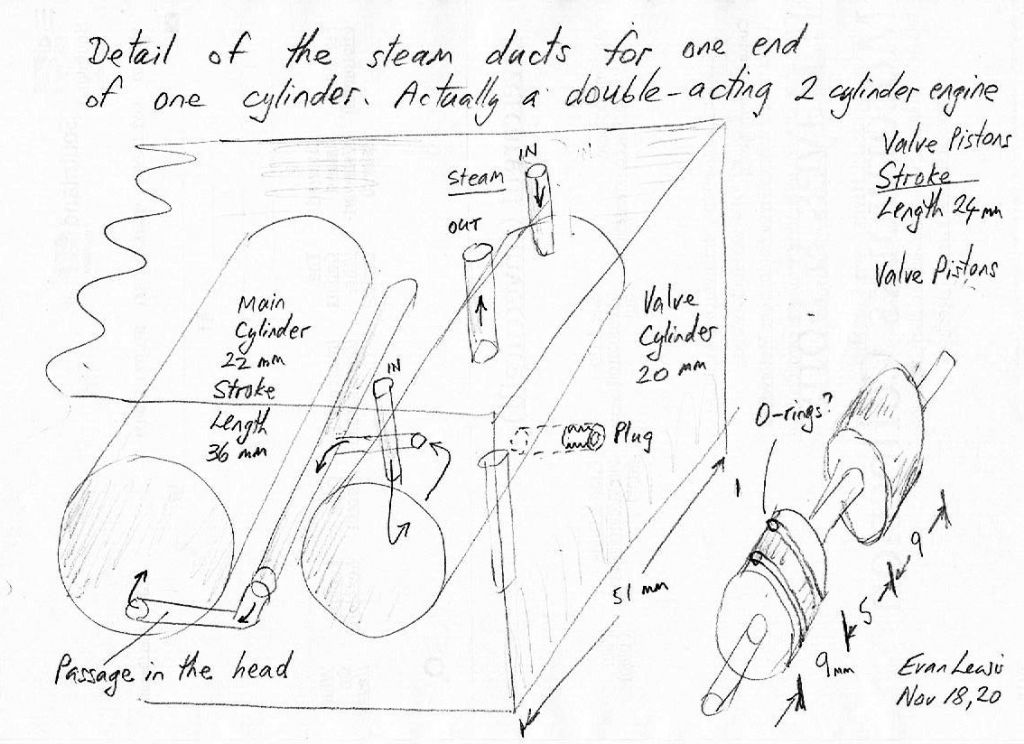
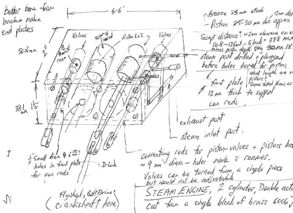
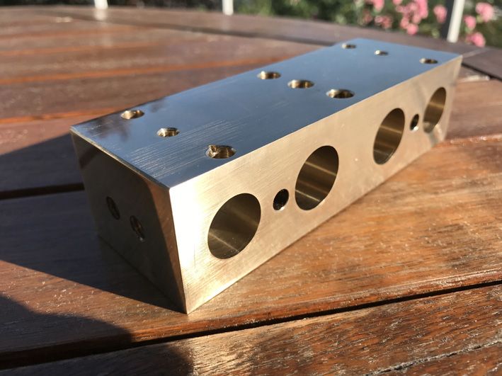
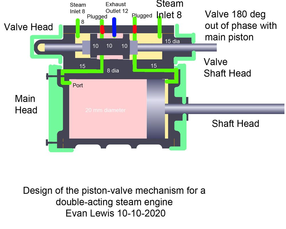
The valve piston works exactly the same way as a D slide valve and the cross section of the piston assembly is exactly the same as the cross section of a D valve. It consists of two pistons, each 9mm long with only 5mm space between them. Steam galleries 6.5mm diameter were drilled from the ends of the cylinder block, straight across the valve cylinder and into the steam gallery described above. Then the holes in the end of the block were tapped and blocked off with 8mm stainless steel grub screws. That is why the 6.5 mm drill was chosen.
The biggest flaw with this design is that the steam galleries are too small. And the large mass of brass will take a long time to heat up resulting in condensation. A third problem is that I have read that you should not use brass with steam because it will corrode. I am not sure how quickly that occurs and wether it is really a problem for a model.
The diameter of the ducts is restricted by the limits of the valving system. I was surprised at how precisely this has to be made so that the inlet and exhaust valves do not open at the same time. Usually slots are used to increase the steam flow. At one stage in the design process I was going to have two sets of these galleries for each piston but forgot about that when I actually came to make it! See photo. Since the holes are 6.5mm and the valve pistons 9mm there is 2.5 mm total overlap giving 1.25 mm steam lap and 1.25mm exhaust lap but i have not been able to find any documentation on how to design the lap. It may be too much? When the main piston is at the mid-point of the cylinder the valve pistons occlude with inlet and exhaust ports.
I have not decided on rings for the pistons. I was just going to manage without rings but that may not be wise, so I think I will use O-rings but could use some tips and tricks to work out how deep to cut the grooves. Should I have rings on the valve pistons – they would have to pass over numerous port holes and might get torn up? Also the valve pistons would ideally be sealed along their whole length.
Also I have not worked out how to seal the glands that the con rods pass through. O-rings here too? Placed inside the bearing surfaces?
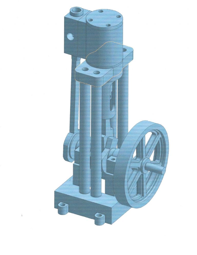
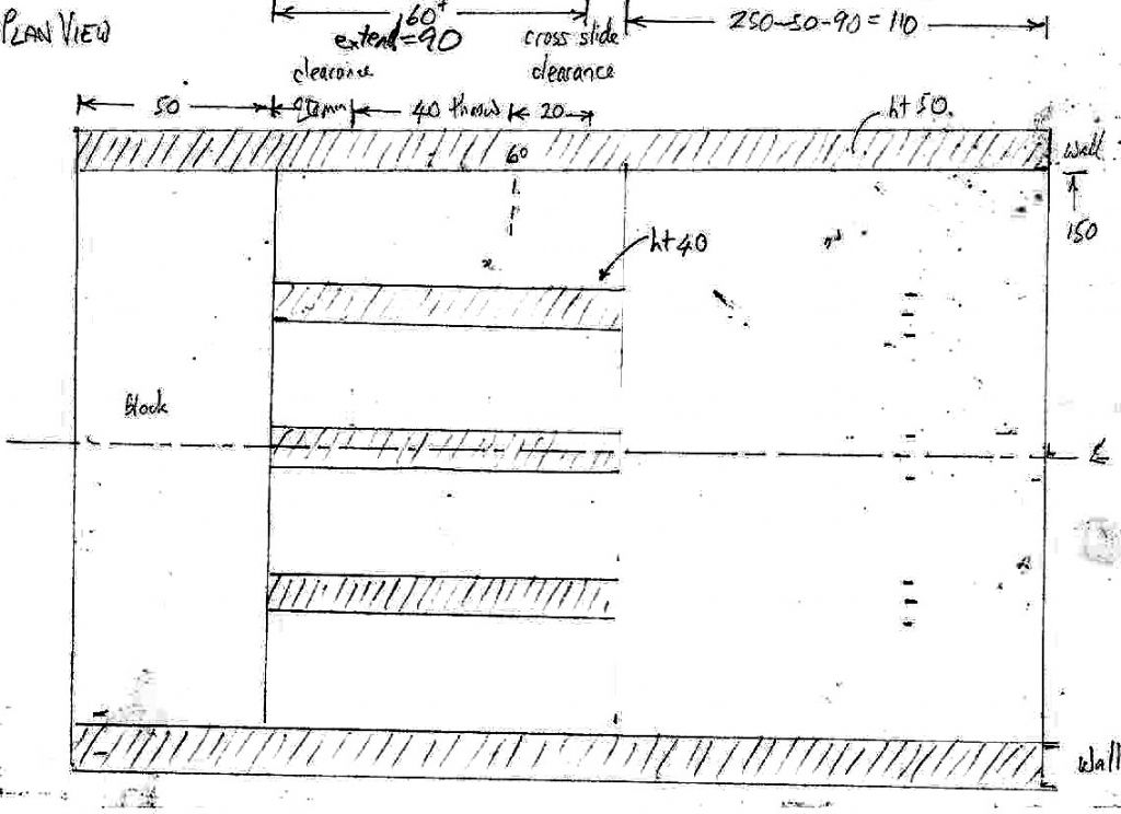
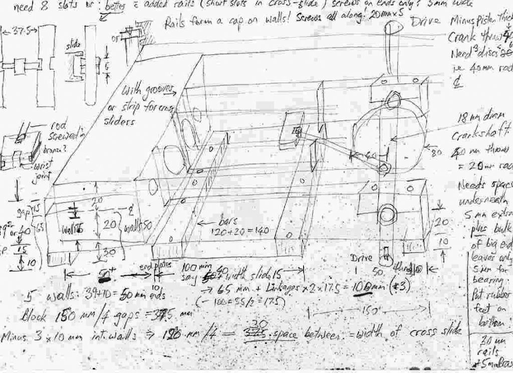
So now I plan to bolt flat plates on each end of the brass bar as a frame with a brass plate for the floor screwed onto the under side of the walls. These walls will support the crankshaft. Then I will place additional 3 walls between the cylinders and mount brass bars 5x20mm across the tops of the 5 walls to make a T shape 100 mm long for the cross heads to slide on.
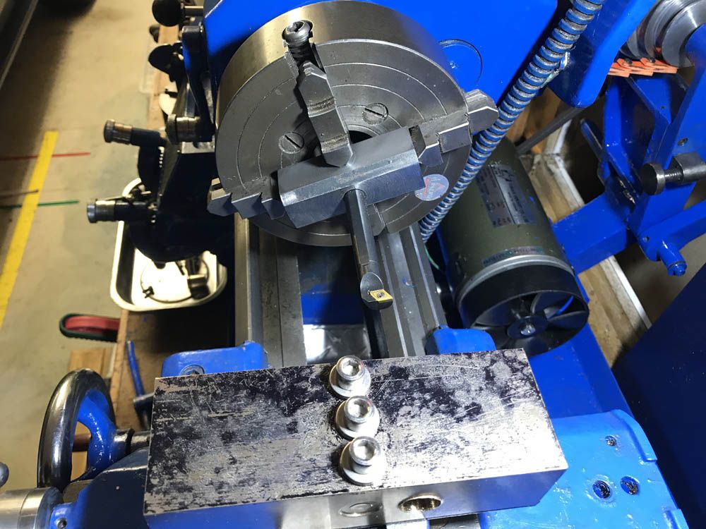
The cross-heads will be about 10mm thick (is weight a concern?) with grooves milled down the side. I do not have a mill but have a milling attachment for the lathe. (Otherwise it could be made from 3 plates screwed together.) The connecting rod will screw into the crosshead and the "swing rod" which connects to the crank shaft will require a wrist joint.
I plan to have double eccentrics for each cylinder so that they can be connected to a C-shaped slot controller to provide forward and reverse and variable power. But in the first instance I will just use one of them to make it a bit simpler until I am sure it will work.
I do have some scrap bronze and all the bearings and cross heads will be made from that.
I also have some interesting scrap I got from a scrap dealer in NZ. This is 80mm diameter solid round bar about 500mm long which he gave me. It was attached to a plate 100mmx10mm and the same length and I was able to remove it. It appears to be very hard magnetic stainless steel but the Menz Shed has an electric hacksaw which will cut off disks.
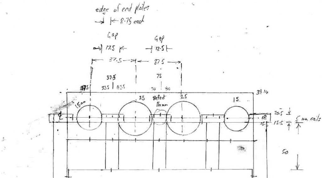
At first I assumed I would be able to make the crankshaft out of a single block but with 36mm swing it is too big. I can just fit the 80mm bar into my chucks but cannot set an offset to turn the bearings for the big ends. So I have decided that I will have to cutoff and face 3 disks and drill holes to place shafts for the big ends. I do not know how they will be kept in place. Probably pins drilled across the holes. Any suggestions here would be helpful. I think that threading these joints would not be sufficiently accurate or rigid. Can it even be done?
Any advice that you can offer would be greatly appreciated!
Evan Lewis.


