Chris V –
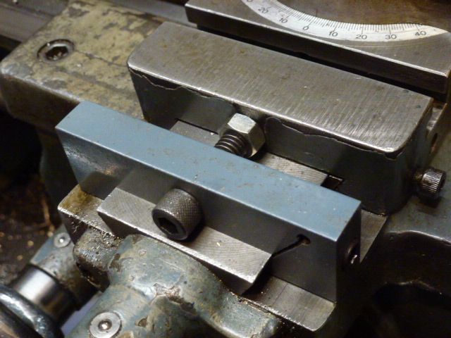
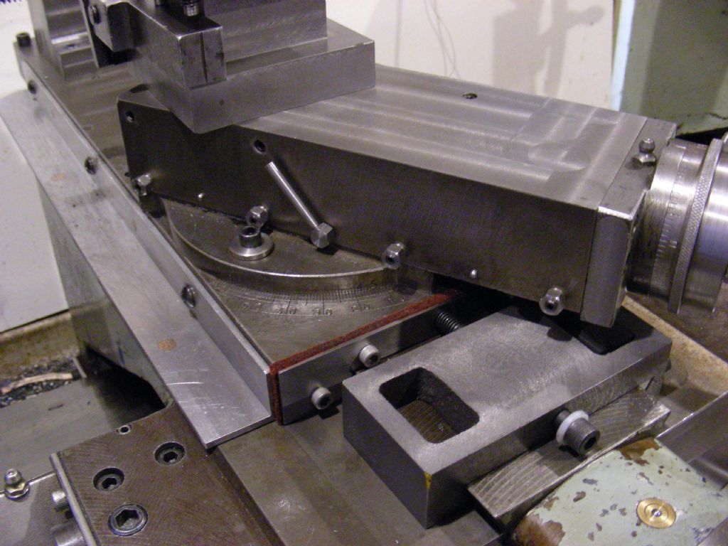
With respect the photo is almost the design. You'd have to measure the lathe to ascertain dimensions. The Allen screw goes through a clearance-hole in the clamp-block, to a tapped hole that happened already to be in the cross-slide. (I wonder what that hole was intended for?). The stop action is thus by the underside of the cap-screw contacting the block.
Note the flexing-point for the clamp is the small hole near the top right edge; the cap-screw that actuates the clamp should be sufficiently far down for proper clamping action without an unduly weak wall between the thread and the block's underside. The clearance hole is just a tad generous, but not overly so if the Vees meet as they should.
'
Larry –
I would agree that stop as made is a bit too slender. The principle is very good and I am only surprised such stops are not more common. It does though, need to be very rigid and positive.
The bracket could be made far more rigid by welding or brazing a triangular gusset across both ends to make a Vee-box form, rather as many angle-plates are cast.
Or replaced by similar machined from a cube.
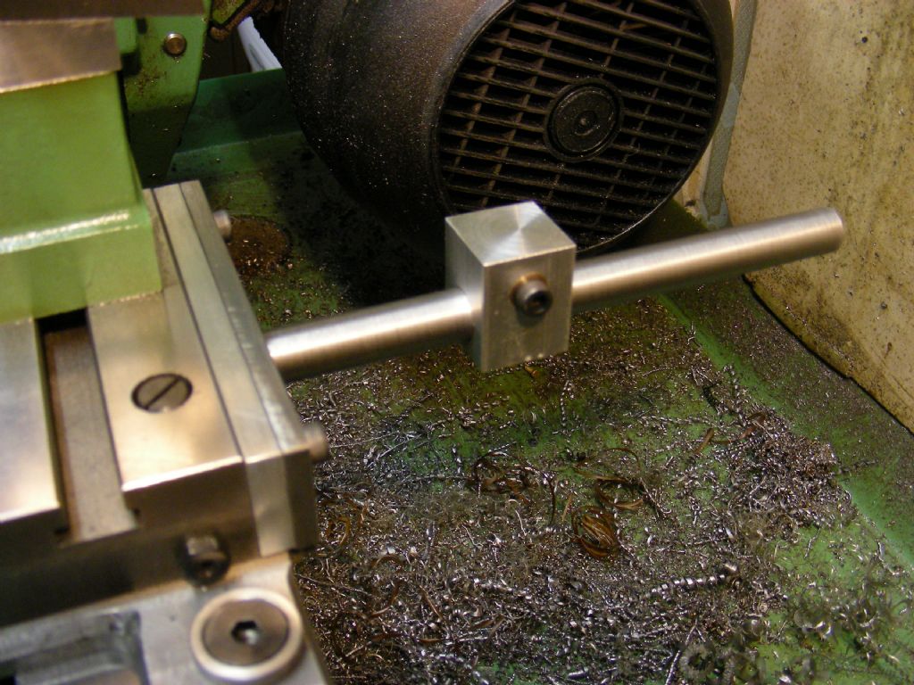
It's a bit hard to see details but the central shaft and whatever it fits in, look a little thin.
'
I have the essence of a 6-station saddle (rather than cross-slide) stop from an old industrial lathe, and the rotary part is a cylindrical sleeve a close sliding fit on a rigid stator. As far as I can tell, its central Allen screw pulled the back of the stator onto a spot-facing on the apron.
The trick is that the stop-screw carrier has as much bearing surface as possible for the rotary part of a unit probably little larger than yours, and it revolves on a part held in the most rigid way it can be. The stop-screws thus thread down inside the wall of the sleeve.
What you might consider is modifying / making new the bracket to be much more rigid. Then, if that does not entirely solve the problem, make the stop-carrier as above: a closely-fitting sleeve pulled back by a hefty screw to a facing on the bracket..
My industrial version had the extra luxury of a detent arrangement and operating-handle, as on a rotary tool-post, but that's for another day!
The length-stops themselves on my example – which I have not used – are square-head screws, 5/16-in BSF I think, with lock-nuts, that met a domed fine-adjustment screw in the end of a bar dimpled for coarse adjustment within its mounting-block. My Myford 7 certainly does not, and the Harrison L5 appears not, to provide for mounting this device.
 Bazyle.


