Muncaster’s Simple Entablature Engine

Advert

Muncaster’s Simple Entablature Engine

Home Forums Stationary engines Muncaster’s Simple Entablature Engine

Viewing 25 posts - 1 through 25 (of 156 total)
  • Author
    Posts
  • #385245
    JasonB
    Moderator
      @jasonb

      With the build series for my rendition of Muncaster's "Simple" Entablature Engine about to begin in ME 4618 I have started this thread for anyone who may have queries or comments about the engine such as alternative materials or construction methods to suit what tools you have.

      Additionally I will post extra photos that would have possibly packed out the article too much but that may still be of use to those building the Engine. Martin is kindly publishing in consecutive magazines so that the build won't be spread over too long a period.

      For those that have not seen my previous posts of the engine here is a video of it running of 2-3psi of air to wet your appetite and hopefully tempt you to give it a go.

       
      The drawings have also been proofed by out occasional member "Gas Mantle" who is a relative beginner, this is a clip of his version running on the "hot stuff"
       
       
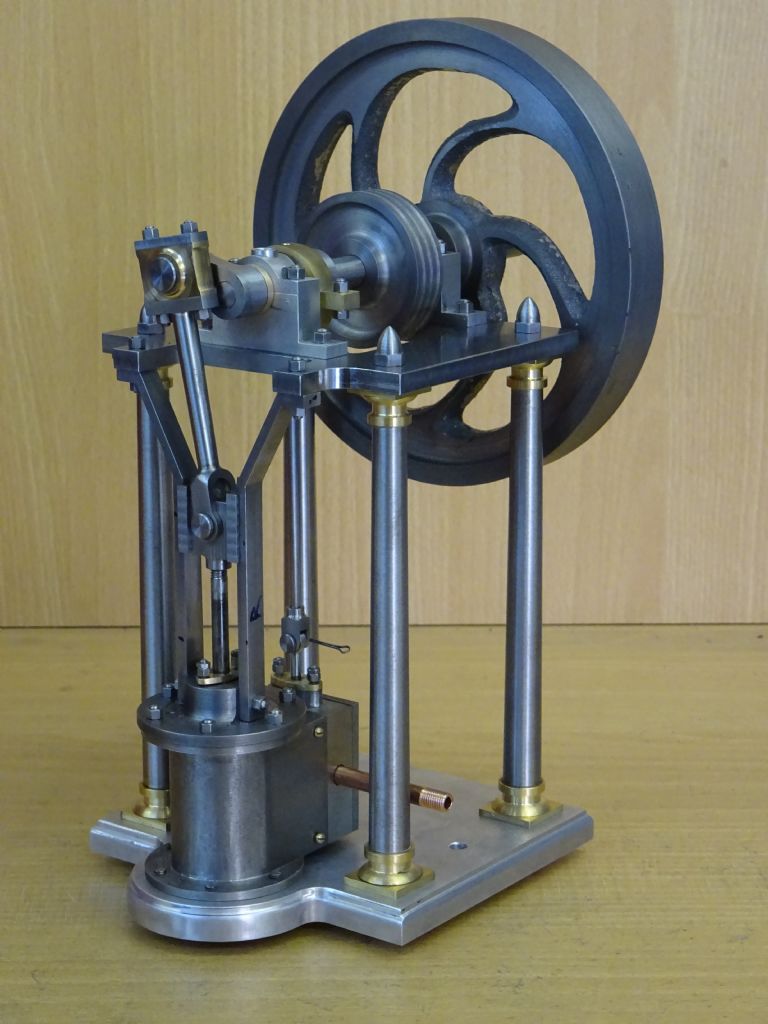
      The naked engine will give a good idea of what materials were used in it's construction
      dsc01350.jpg

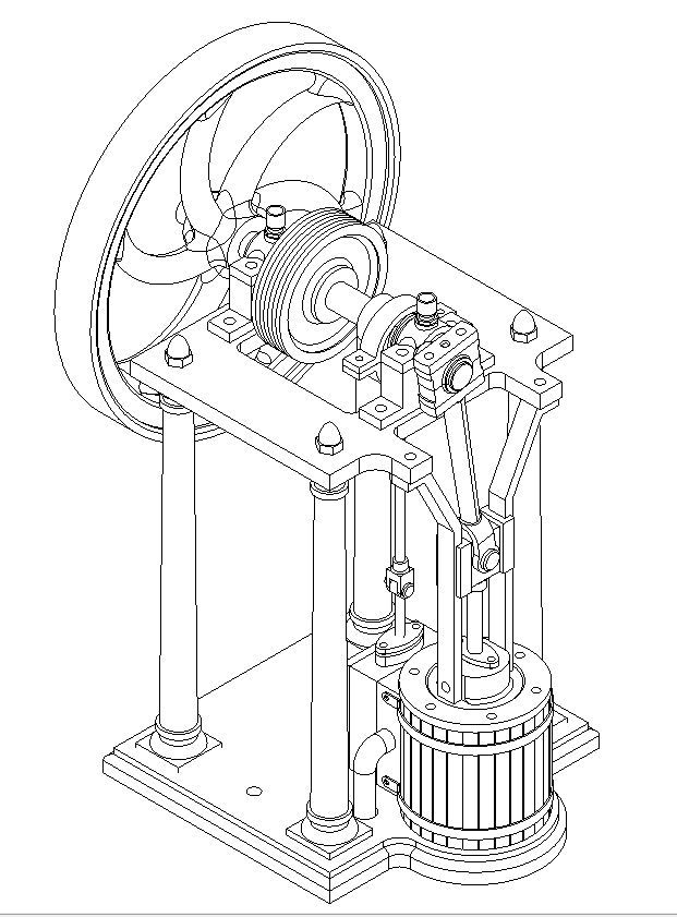
      And if you prefer a sketch to the 3D rendering that is shown in the magazine then this is for you

      sketch.jpg 


      Edited By JasonB on 25/07/2019 19:05:12

      Advert
      #3351
      JasonB
      Moderator
        @jasonb
        #420953
        JasonB
        Moderator
          @jasonb

          Additional content to go with part 1

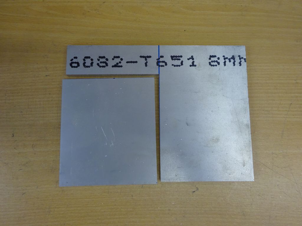
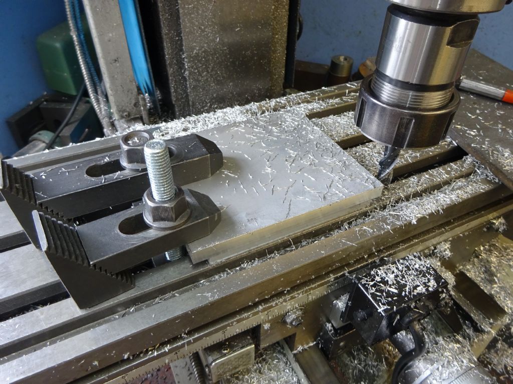
          8mm 6082-T6 aluminium plate with the material for the base Plate cut out.

          dsc01188.jpg

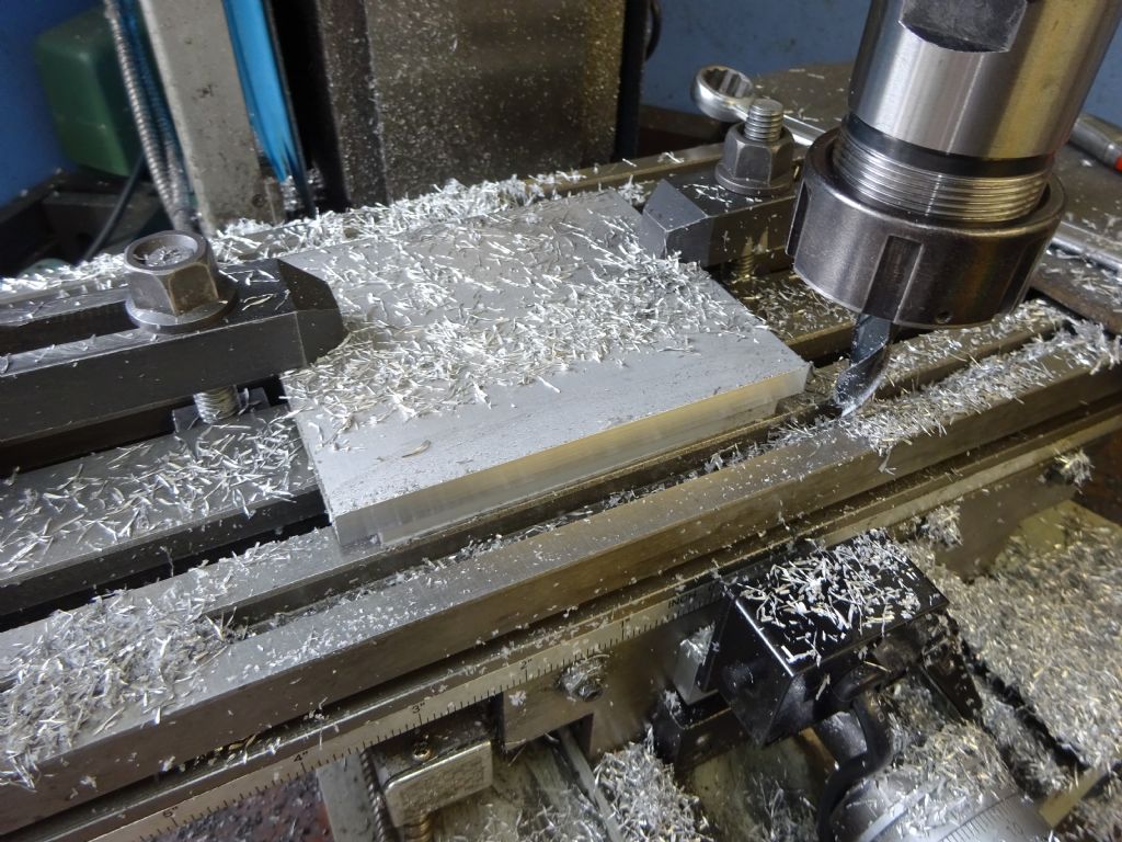
          Initial cuts to bring front and back edges to size

          dsc01190.jpg

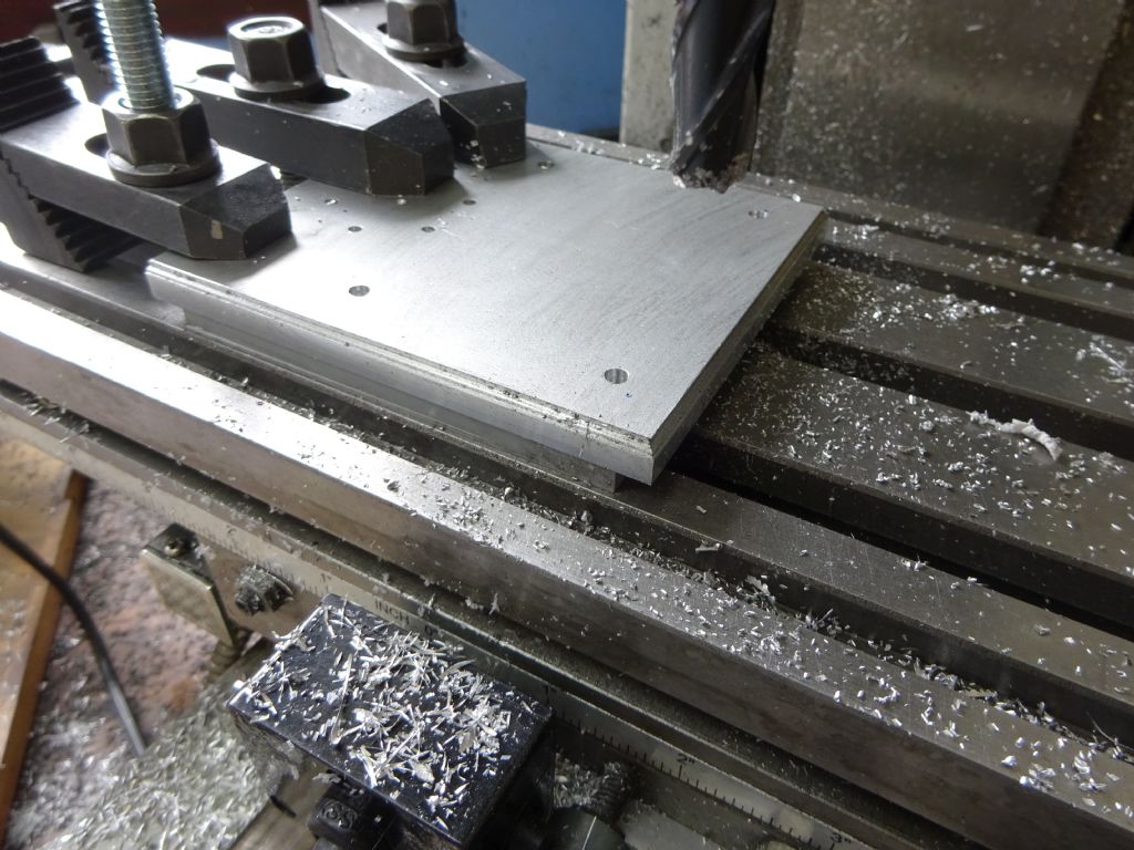
          Clamps moved to do the sides

          dsc01191.jpg

          Freehand ground cutter used to form the 2mm radius decorative moulding, again clamps moved to suit.

          dsc01193.jpg

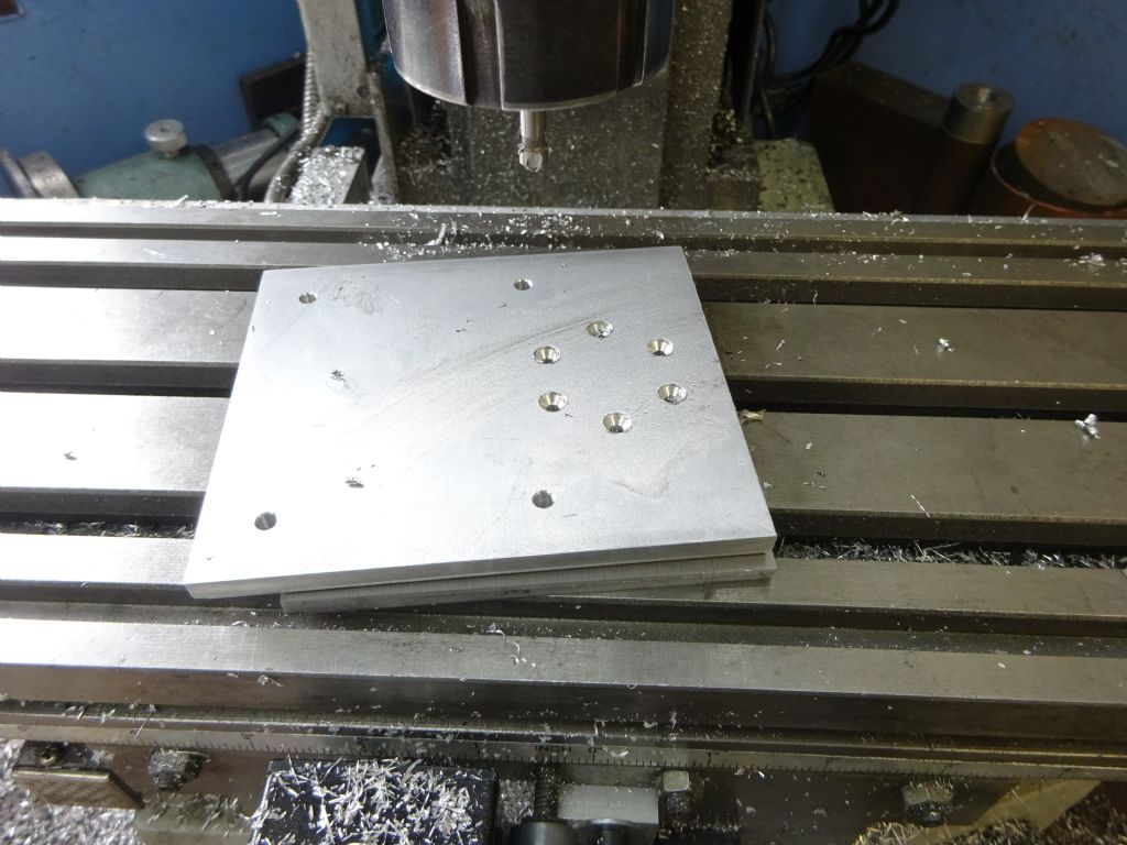
          Countersinking the underside of the six cylinder fixing holes for socket head csk screws as they won't be seen.

          dsc01194.jpg

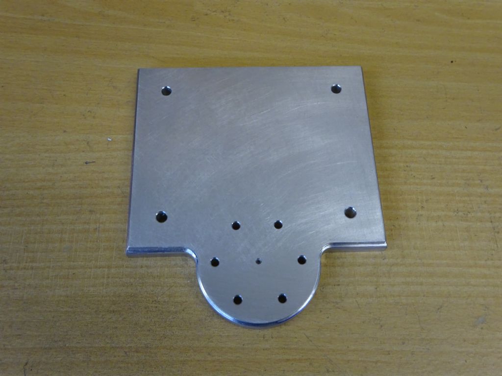
          The almost completed base plate

          dsc01196.jpg

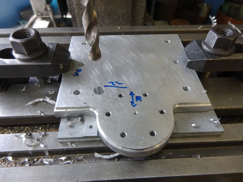
          Adding the exhaust pipe hole, other builders should do this at the time all the other base holes are added unless they want to use a different route for the exhaust

          dsc01347.jpg

          J

          #420955
          Former Member
          Participant
            @formermember19781

            [This posting has been removed]

            #421023
            geoff walker 1
            Participant
              @geoffwalker1

              Hi Jason.

              That sounds good, issue 4618. I don't take M.E. mag on a regular basis but as this engine has captured my interest I'll get 4618 when it comes out. Do you know how many issues will cover the whole engine build?

              I notice you have deviated from the standard muncaster pedestals. Having the split line on the central bearing and the housing at the same level seems to me a much better arrangement. The muncaster pedestals look unnecessarily complicated and would for me be difficult to make.

              I assume you have scaled up the muncaster drawings 1/32" = 1mm which increases the bore size from 3/4" to your "favoured" 24mm.

              Yes, looks interesting Jason and like others I welcome the addition of this supplementary build thread.

              Geoff

              #421030
              JasonB
              Moderator
                @jasonb

                Thank's for the interest Geoff, not sure how many issues it will get spread over but maybe 8-9 if Martin continues to give it 3 pages per issue, there are 15 drawings and two are in the first instalment but there is not so much text associated with those parts

                Yes the pedestals are a bit easier to make that way and I also left them square sided rather than having to turn them, though with the basic mechanicals set out on my drawings the model could be embelished if the builder wanted.

                Yes 1/32" = 1mm as it's a more manageable size and more beginners are likely to be brought up with the metric system and using metric tools and machines. It could also be enlarged working at 1mm=1/16" or reduced back to the original.

                J

                #421472
                Roger Clark
                Participant
                  @rogerclark

                  Where's the flywheel from Jason?

                  #421488
                  JasonB
                  Moderator
                    @jasonb

                    There will be a link in the installment with the flywheel but this e-bay seller usually has them but sods law he does not have one listed at the moment. He used to do the casting for College Engineering before they changed hands.

                    #421516
                    Roger Clark
                    Participant
                      @rogerclark

                      Thanks Jason, yes it's a shame about College Engineering, there were some useful castings that are now always out of stock.

                      #421682
                      Ron Laden
                      Participant
                        @ronladen17547

                        Jason, I dont want to interrupt this thread but with the running video you mention running off 2-3 psi, is that the norm with small stationary engines i.e only needing low pressure to run. I imagined they would need quite a bit more than that but obviously not.

                        Ron

                        #421685
                        duncan webster 1
                        Participant
                          @duncanwebster1

                          I made a Williamson engine many years ago, no piston rings or piston rod packing, just good fit. It will just run on lung pressure

                          #421687
                          JasonB
                          Moderator
                            @jasonb

                            For display when the engine is not running under any load you don't need much pressure and if it has been made well with minimum friction will not require much force to turn it over.

                            As soon as you put a load onto it you will need up up the pressure as you can't get effort out if you don't put effort in.

                            #421706
                            not done it yet
                            Participant
                              @notdoneityet

                              Another question. This one about design layout. Why is the power side only supported on one side ie outboard and the valve gear is on a shaft supported between bearings? Ease of alignment? Simplicity to buid? So it can be seen easier?

                              Nice engine, but design seems odd, to me.  Even though I know there are umpteen small engines with no rear crank support

                              Edited By not done it yet on 30/07/2019 17:50:17

                              #421717
                              JasonB
                              Moderator
                                @jasonb

                                As this is his "simple" design it is a lot easier to make a crank with just one web on the end of the shaft and a pin into that than would be needed if say the cylinder were set centrally between the columns. On the full size it probably kept the costs down and made erection on site a lot easier.

                                If I write up a few more of the similar sized Series 24mm bore engines than construction will become a little more complicated with each as cylinders become fabricated and the cranks sit between bearings. And maybe move on to ones that need more exacting fits such as hot air and IC engines.

                                Edited By JasonB on 30/07/2019 19:02:49

                                #421724
                                Ian Johnson 1
                                Participant
                                  @ianjohnson1

                                  Really nice work Jason, I like the design especially as it is open to view to see how the mechanism operates.

                                  If I do make one how big is the flywheel? I was wondering if it could be CNC'd on my KX1? If the castings aren't available.

                                  Ian

                                  #421726
                                  JasonB
                                  Moderator
                                    @jasonb

                                    You might be a bit tight on the Y-axis as it is 115mm OD but if starting with a circular blank about 100mm on the Y-axis may be enough using a 6mm cutter.

                                    I suppose the spokes could be cut from plate and set into a rim in which case assuming you start with a turned disc then with a 6mm dia cutter you would only need 90mm movement.

                                    A Minnie flywheel would be about the same size though does not have the curved spokes which are quite nice.

                                    #421740
                                    Ian Johnson 1
                                    Participant
                                      @ianjohnson1

                                      Yes the curved spokes are very pretty, that's why I was thinking about CNC if castings aren't available, most things can be machined from solid, but like you say space is a bit tight on a little KX1.

                                      #421741
                                      JasonB
                                      Moderator
                                        @jasonb

                                        Another option may be to set up the blank so it can be indexed 6 times and just run code so that it cuts one spoke and half of each space either side, then index around an run the code again.

                                        I'll sort you out the STEP file tomorrow if you want to play with the CAM

                                        #421745
                                        Colin Heseltine
                                        Participant
                                          @colinheseltine48622

                                          Jason,

                                          That looks very nice. Do you have any video showing how you produced the radius around the cylinder mounting on the base plate and then changed from external radius to internal radius's and achieved it all nicely flowing from one radius to the next. Or was this done on your CNC machine?

                                          Colin

                                          #421767
                                          Ian Johnson 1
                                          Participant
                                            @ianjohnson1
                                            Posted by JasonB on 30/07/2019 20:52:36:

                                            Another option may be to set up the blank so it can be indexed 6 times and just run code so that it cuts one spoke and half of each space either side, then index around an run the code again.

                                            I'll sort you out the STEP file tomorrow if you want to play with the CAM

                                            Good idea! and yes please I'll have a play with the step file that's very kind of you. I'm using Vectric Vcarve if that makes any difference?

                                            I've been playing around with the KX1 doing some plastic engraving over the past few days so it will make a change to do some metal stuff.

                                            Ian

                                            #421771
                                            Paul Lousick
                                            Participant
                                              @paullousick59116

                                              Another question. This one about design layout. Why is the power side only supported on one side ie outboard and the valve gear is on a shaft supported between bearings? Ease of alignment? Simplicity to buid? So it can be seen easier? Nice engine, but design seems odd, to me. Even though I know there are umpteen small engines with no rear crank support.

                                              The outboard crank design was also used on big engines, like the Case 150 HP road locomotive shown in this Youtube video

                                              Paul.

                                              **LINK**

                                              #421786
                                              JasonB
                                              Moderator
                                                @jasonb
                                                Posted by Colin Heseltine on 30/07/2019 21:05:38:

                                                Jason,

                                                That looks very nice. Do you have any video showing how you produced the radius around the cylinder mounting on the base plate and then changed from external radius to internal radius's and achieved it all nicely flowing from one radius to the next. Or was this done on your CNC machine?

                                                Colin

                                                Will explain it later if what I said in the article was not clear but the engine was made before I had the CNC.

                                                Edited By JasonB on 31/07/2019 07:14:31

                                                #421789
                                                JasonB
                                                Moderator
                                                  @jasonb

                                                  As for HP through a crank with support on one side I can beat Paul's with a 600HP Snow Engine and there are some big corliss steam engines about too.

                                                  Edited By JasonB on 31/07/2019 07:28:23

                                                  #421934
                                                  JasonB
                                                  Moderator
                                                    @jasonb
                                                    Posted by Colin Heseltine on 30/07/2019 21:05:38:

                                                    Do you have any video showing how you produced the radius around the cylinder mounting on the base plate and then changed from external radius to internal radius's and achieved it all nicely flowing from one radius to the next.

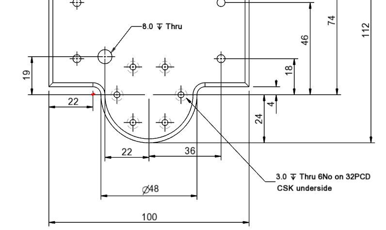
                                                    Looking at the drawing at the bottom left of the base is a dimension of 22mm in from the edge to the ctr of the internal corner radius which I have marked in red which gives a distance from the cylinder Ctr datum point of 28mm (half base width less 22mm) in the X-axis and zero in the Y-axis. As the front edge of the base is 4mm from this point an 8mm cutter can be used as per the text.

                                                    munky base snip.jpg

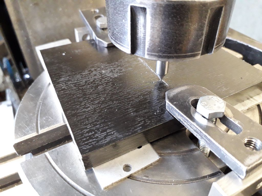
                                                    First thing to do is set the rotary table up on the mill with it's axis directly below that of the mill and zero your handwheel dials or DRO. Then turn the table until the scale reads zero and clamp the work to the table with some packing between and make sure it is square to the lathes axis and the ctr of the cylinder is lined up to the mill spindle.

                                                    20190731_165904.jpg

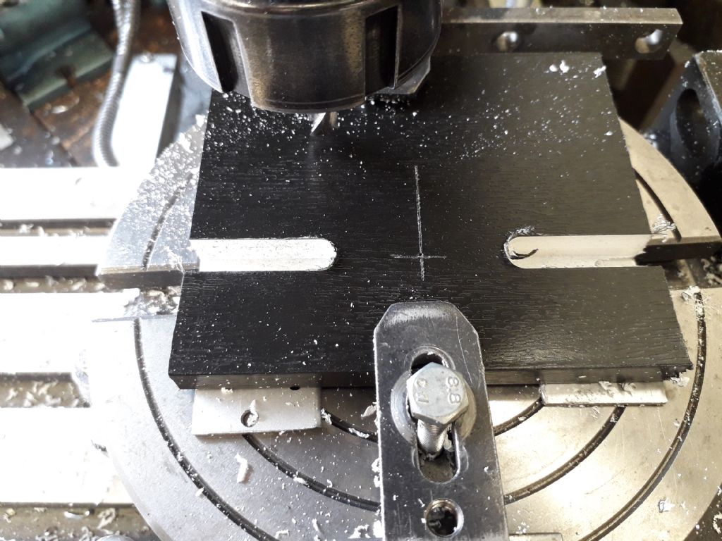
                                                    Pop an 8mm cutter in your holder of choice, lock the Y-axis at zero and then cut in from each edge to 28mm from the cylinder ctr. Assuming a bench top mill then something like 1mm deep per pass will do or more if you have sawn away most of the waste before milling. You should then end up with two slots like this.

                                                    20190731_170652.jpg

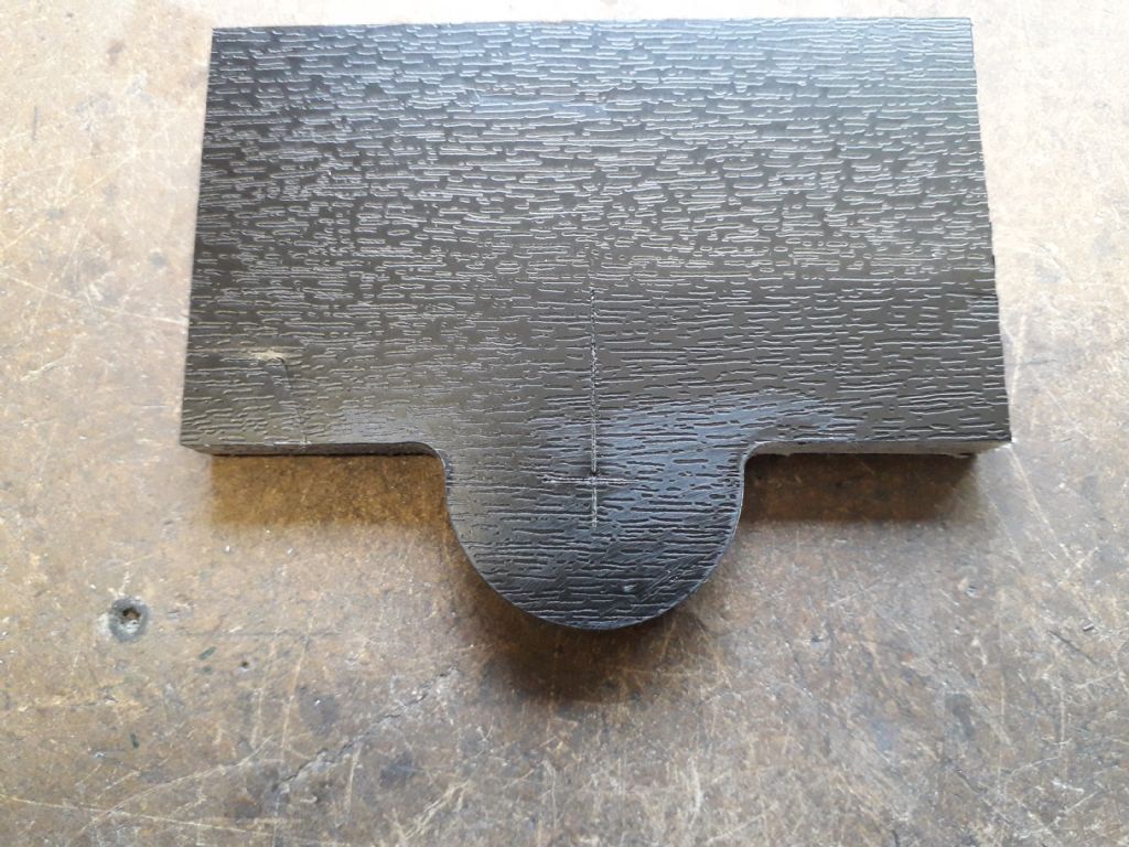
                                                    Reposition the clamps to the sides and you can now also lock the X axis at -28, 0 and bring the cutter back down to take your first cut around the curve which will start from zero degrees and end at 180deg, repeat this until you have cut ring through and hopefully have a shape like this. before rushing to admire your work run the decorative moulding around the curve and front edges while the work is correctly located.

                                                    20190731_172409.jpg

                                                    Do not dispair if you don't have a rotary table, just mill the two slots and then saw and file the half circle. If you take this approach it would be better to build up the base from a piece of 6mm plate that can then have the 2mm moulding filed onto it and then add a 2mm thick plate ontop that is 2mm smaller all round to produce the quirk.
                                                    #423220
                                                    JasonB
                                                    Moderator
                                                      @jasonb

                                                      Additional content to go with Part 2.

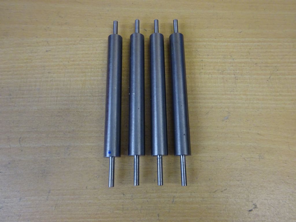
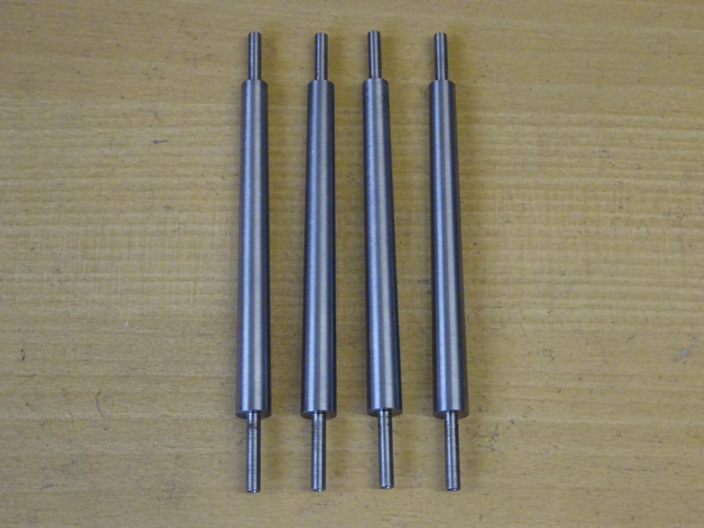
                                                      The four embryo columns with the end spigots turned and ctr drilled.

                                                      dsc01208.jpg

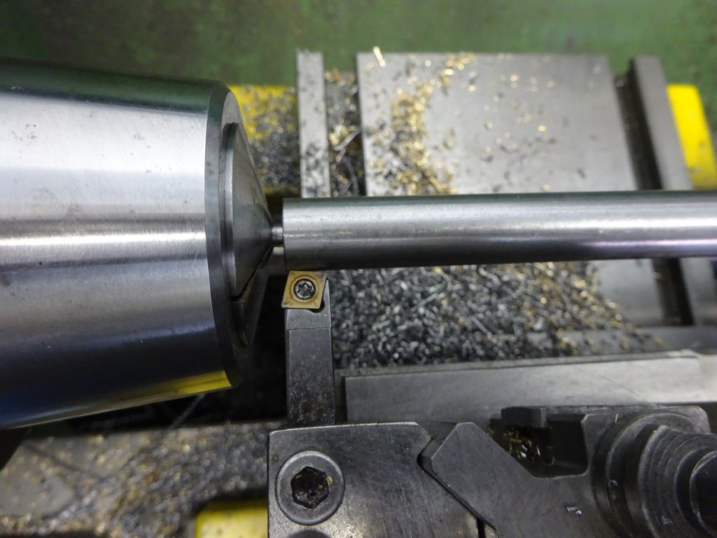
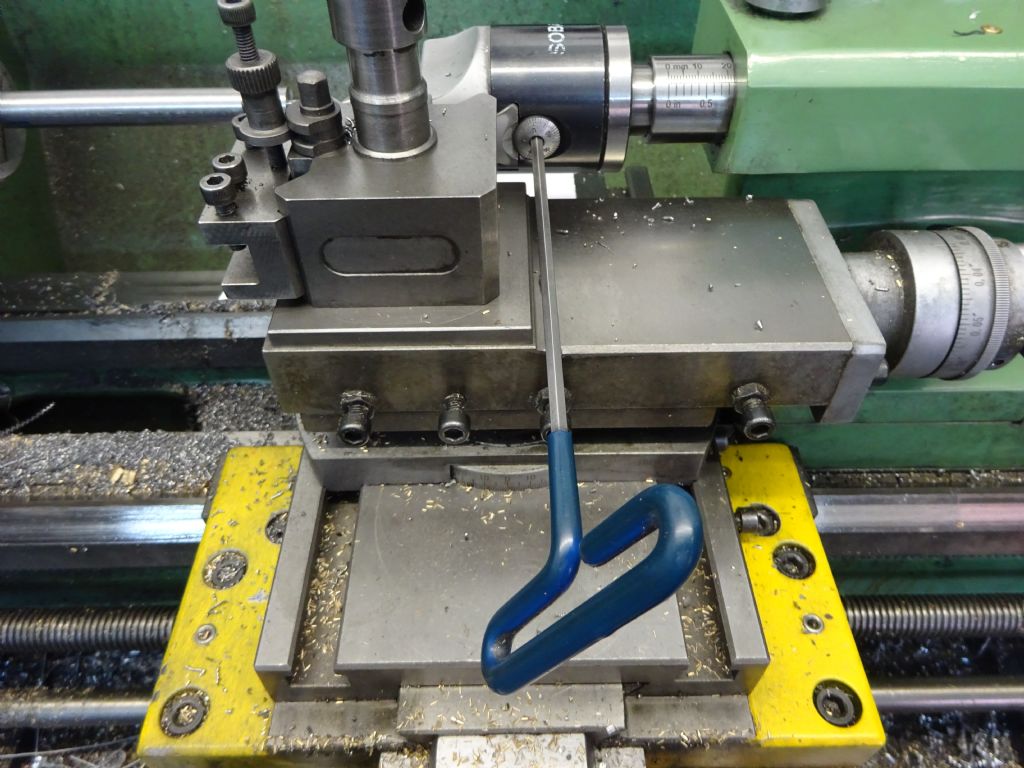
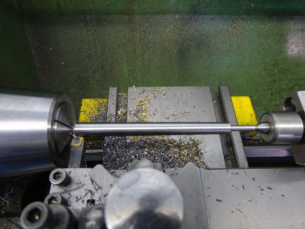
                                                      This is the method I used to cut the tapers using a boring head to offset the centre but the same can be done by offsetting the tailstock.

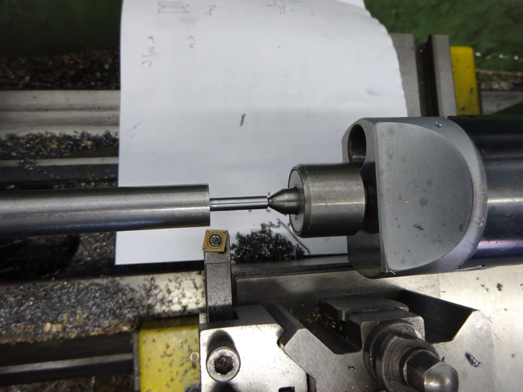
                                                      Hold by the bottom spigot with enough room to let the tool clear the cut and touch off against the 12mm diameter.

                                                      dsc01210.jpg

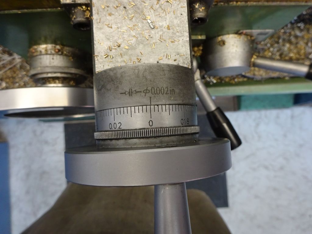
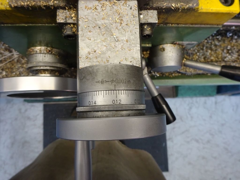
                                                      Zero the handwheel dial or DRO if you have one.

                                                      dsc01211.jpg

                                                      Wind the tool away by half the difference in diameters in this case 1mm [(10-8) / 2], my dial reads in diameter so I moved it 2mm (0.079" )

                                                      dsc01212.jpg

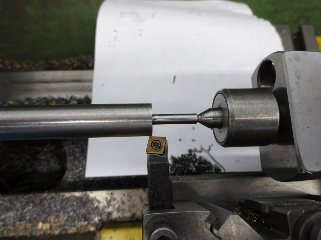
                                                      Now move the carrage so that the tool is at the other end of the work and you will see the gap

                                                      dsc01213.jpg

                                                      Now move the ctr towards you until the tool touches off on the work

                                                      dsc01215.jpg

                                                      dsc01214.jpg

                                                      It is now just a case of turning along teh length in a couple of passes preferably using power feed until your cross slide reads zero and you should end up with a nice taper.

                                                      dsc01209.jpg

                                                      Repeat for the other 3 columns

                                                      dsc01220.jpg

                                                    Viewing 25 posts - 1 through 25 (of 156 total)
                                                    • Please log in to reply to this topic. Registering is free and easy using the links on the menu at the top of this page.

                                                    Advert

                                                    Latest Replies

                                                    Home Forums Stationary engines Topics

                                                    Viewing 25 topics - 1 through 25 (of 25 total)
                                                    Viewing 25 topics - 1 through 25 (of 25 total)

                                                    View full reply list.

                                                    Advert

                                                    Newsletter Sign-up