My First ‘Real’ Steam Engine ?

Advert

My First ‘Real’ Steam Engine ?

Home Forums Stationary engines My First ‘Real’ Steam Engine ?

Viewing 14 posts - 1 through 14 (of 14 total)
  • Author
    Posts
  • #331275
    Iain Downs
    Participant
      @iaindowns78295

      Recently, I built my first wobbler, which wobbles very nicely thank you. I was very excited by this but many of my friends said, 'yes, but what is it for?'.

      Needless to say I don't need to justify that in this forum! However, this made be determine that my next model would be a steam engine which could actually do something useful – I started the process in another post where (as usual) I received a lot of help and corrections.

      But (for reasons devoid of logic, though in part due to the sheer cost of kits) I want to do my own design from scratch.

      My main design parameters are:- bore 2 inches, stroke 3 inches, double action, d valve, vertical (though I'm not tied to that) and single direction. (at least to start with – valve gear adds too much complexity). So pretty simple.

      At the moment I'm struggling with the valve design. Most of the posts and articles I've come across assume that you have a design already and want to add a bit of lap and lead.

      I gather that what I need to aim for is for the inlet to be open for the first 25 – 30% of the stroke and then closed until near the end. The outlet should be open from as early as possible until just near the end of the exhaust stroke.

      I'm struggling to find any approach other than trial and error to get something which matches these settings.

      Being of a geeky background, I've tried to do this by creating an interactive graphical simulator which you can find here.

      The default settings there are about the closest I've come to what I think is reasonable. However, I have only managed that by reducing the D travel to less than the valve width which doesn't seem right.

      I'd be obliged if someone who understands this stuff would have a look and suggest some more appropriate settings.

      I have the impression that the connecting rod has to be long compared to the stroke (the shorter the con rod the further the motion is from a sine wave). Is 2x about right or 3x?

      Finally (for now), what is a good material for the crank? I don't expect this to be particularly stressed so I would think that most hobby steels would do?

      Cylinder and valve will be cast iron.

      Thanks in anticipation…

      Iain

      Iain

      Advert
      #3325
      Iain Downs
      Participant
        @iaindowns78295

        Trying too hard again?

        #331278
        JasonB
        Moderator
          @jasonb

          Does not look to open the inlet very much or for a reasonal length of time. Will have a better look and see if I can simulate one of my engines.

          J

          #331325
          Jon Cameron
          Participant
            @joncameron26580

            I had a play with your simulator, I quite liked messing with that.

            The settings I got were,

            Bore = 50, Stroke = 75, D valve = 18, valve travel =4, inlet width =4, lap = 0, lead =90.

            I'l see what Jason comes back with as he has much more experience in design than I do. Though the settings above made for little lag in the cylinder, meaning the cylinder had steam admitted or exhaust, but no overlap of the two.

            #331351
            JasonB
            Moderator
              @jasonb

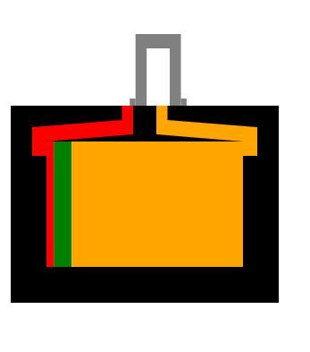
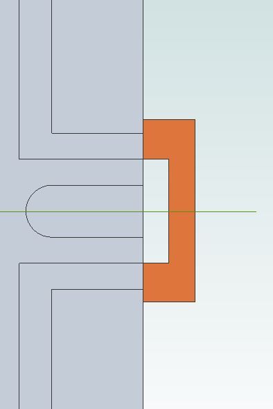
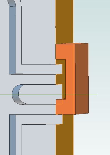
              Something does not look right on the simulator. This was with the valve width set at 12.7mm and the inlets at 3.125. yet the valve only looks to be half the width of the inlet

              valve width.jpg

              Should look like this mid point

              fowler valve.jpg

              full ecc throw

              fowler valveopen.jpg

              Try these details

              Valve recess 12.7mm

              Eccentric throw 4.7mm which you call travel though travel is twice throw although simulator allows for this

              Inlet 3.125mm

              Lap 1.6mm

              Angle 120deg

              Inlet is fully open at full ecc throw

              This is from the 2" Fowler A7 1.375 bore x 51.00 stroke and capable of pulling two people around all day. so a design that works. Just multiply by 1.5 to get some figures for your engine.


              Edited By JasonB on 10/12/2017 08:51:08

              #331395
              Iain Downs
              Participant
                @iaindowns78295

                Hi, Jason – many thanks for the help.

                After spending the morning mucking around with my code (that or an unheated shed….), I've come to the conclusion that the code is fine, but the documentation is poor!

                The Valve width is the width between the insides of the D valve. The no lapped D (so the outside of the valve width) is the same as the width of the inlet and then I add Lap..

                centre.jpg

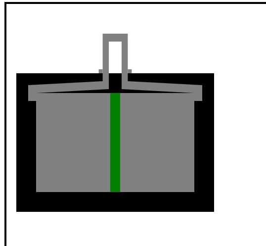
                I've plugged your numbers (at least I think I have), except that m DValve is wider, which i don't think will affect this.

                jason.jpg

                What I'm seeing is that the cut-off is about 80% whereas my reading would expect about 25%.

                Making these changes produces something a little more like my reading expects, but does not open the valves much

                travel => 2.5

                inlet => 4

                Lap =>2

                Lead => 140

                So I could better see what's happening there is now a manual mode where you can set the crank angle. You may need to Ctrl F5 to refresh the browser to see the new version.

                Iain

                #331398
                JasonB
                Moderator
                  @jasonb
                  Posted by Iain Downs on 10/12/2017 12:07:39:


                  I've plugged your numbers (at least I think I have), except that m DValve is wider, which i don't think will affect this.

                  jason.jpg

                  What I'm seeing is that the cut-off is about 80% whereas my reading would expect about 25%.

                  Making these changes produces something a little more like my reading expects, but does not open the valves much

                  travel => 2.5

                  inlet => 4

                  Lap =>2

                  Lead => 140

                  Ok I've entered my figures and get full opening of the inlet which you would expect as opening plus lap = eccentric throw ( 4.7 + 2.4 = 7.1)

                  The 4 values you list will give very little opening as your eccentric throw is so small so you only open 0.5mm once the lap has been subtracted from the travel. I'd expect that sort of eccentric throw on a 3/4" to 1" bore engine

                  Your lead of 140 deg seems very large too, for the display engines I usually set the lead to be 100-110deg and the Fowler that does work is 120deg

                  Edited By JasonB on 10/12/2017 12:34:05

                  #331430
                  Ed Duffner
                  Participant
                    @edduffner79357

                    That's a fascinating simulator Iain. It really helps to visualise the set-up and action.

                    In an efficient design where would a piston be – at or just before/after TDC when steam is introduced into the cylinder? …and likewise the exhaust valve?

                    Regards,
                    Ed.

                    #331446
                    Iain Downs
                    Participant
                      @iaindowns78295

                      I guess that's one of the things I'm trying to understand.

                      From my reading (mainly a pdf found on the web entitled 'Steam Engines, are the complicated or what' – apparently dated 19220, a 'medium speed engine' would have a Cut off 1/4 to 1/3.

                      The exhaust should close before the end of the stroke to buffer the piston and at a fast engine, the inlet can also start early.

                      Unfortunately, I'm stumbling around in the dark, theory-wise. I get the basic principles, but the details are eluding me.

                      Jason, I can easily make the inlet ports bigger (and scale things up) – in any event I'd planned quite a wider (rectangular) port so the area should be decent.

                      I wonder, also if I'm reading too much about trains rather than models and the model world is less concerned about the expansion phase (which reduces power but increases efficiency) which is why there is such a contrast between the 25% cutoff I'm trying to achieve.

                      With your numbers the cutoff is nearer 80% and there is very very little expansion.

                      Iain

                      #331454
                      JasonB
                      Moderator
                        @jasonb

                        I would not enlarge the inlets, more a case of increasing the small eccentric throw to open more of the inlet, not much point in having your 4mm inlet any lorger if you are only going to uncover 0.5mm of it.

                        I know earlier you said you did not want to do reversing gear but it does have the advantage of making it very easy to alter the valve travel. The figures I gave for the Fowler would be a full notch and would be used when the engine is having to work hard eg going up a steep hill with a waggon full behind but if the engihe were not towing a load and just running along on flat ground the driver would notch it back maybe to 1/3 the movement to save on steam. You can do the same with your engine, allow it to fully open the ports when needed but then notch it back when under less load or when just running for display.

                        The Fowler figures are for a traction engine and as I said that will happily pull two adults about so doing real work not just a display case model. The Fowlers ports are quite wide 1" x 1/8" inlet, 1/4" exhaust and scaled from full size though as they have drilled passages they won't flow as much steam as the full size could and therefore you get more losses

                        Edited By JasonB on 10/12/2017 16:42:58

                        #331460
                        Neil Wyatt
                        Moderator
                          @neilwyatt

                          Late cutoff is good for engines run on air.

                          Advance (opening the steam inlet before TDC) is essential for fat running engines as it cushions the pistons at the end of the stroke and gives smoother running.

                          #331463
                          Iain Downs
                          Participant
                            @iaindowns78295

                            Thanks for this, Jason.

                            Actually, I would design the thing so there is space for some gears in a second incarnation, but I'm trying to keep things simple to start with.

                            One thing which worries me after seeing some U Tube videos is the size of the flywheel (for the 3 inch – comparable to what I'm trying to bodge). It seems to be around a foot in diameter which is substantially in excess of my ability to machine!

                            I am somewhat inclined to simply use your figures (scaled) rather than trying to be too clever. Having said that replacing the eccentric and the D valve would not be the end of the world if I wanted to experiment.

                            Iain

                            #331466
                            JasonB
                            Moderator
                              @jasonb

                              You could come down on dia if you beefed up the flywheel or used a solid one as found on marine engines where the hull would get in the way of a large flywheel. The traction engine flywheels are actually quite light in the rim so even a heavy spoked one of smaller dia would be an option as would twin flywheels and/or a heavy pulley

                              This is a 2/3rds scale model with an 8" flywheel, cylinder bore of 1.625" and stroke of 3" but the flywheel is quite heavy construction and it has a heavy pulley, the original had 12" flywheel, 2.5" bore and 4.5" stroke.


                              If you want to punch the numbers then 17, 4, 3.125, 0.8, 110


                              Edited By JasonB on 10/12/2017 17:32:32

                              Edited By JasonB on 10/12/2017 17:33:10

                              #331472
                              Iain Downs
                              Participant
                                @iaindowns78295

                                Thanks, again.

                                I see this one has a slide to support the piston rod. I was going to forgo this, as it's a horizontal engine.

                                Do you think it necessary?

                                Iain

                              Viewing 14 posts - 1 through 14 (of 14 total)
                              • Please log in to reply to this topic. Registering is free and easy using the links on the menu at the top of this page.

                              Advert

                              Latest Replies

                              Home Forums Stationary engines Topics

                              Viewing 25 topics - 1 through 25 (of 25 total)
                              Viewing 25 topics - 1 through 25 (of 25 total)

                              View full reply list.

                              Advert

                              Newsletter Sign-up