Boring bar ?

Advert

Boring bar ?

Viewing 12 posts - 1 through 12 (of 12 total)
  • Author
    Posts
  • #177012
    Gordon W
    Participant
      @gordonw

      I have a cylinder to make from steel, Dimensions , about-150mm long, 75mm O/D ,and 60mm bore. I was going to chuck it and use a fixed steady and long boring bar after drilling from both ends. I have been reading about between centers boring bars and bolting the job to the table, I can just about manage this on my lathe. Question is whats best? Any advantage in between centers boring ?

      Advert
      #32428
      Gordon W
      Participant
        @gordonw
        #177020
        Chris Gunn
        Participant
          @chrisgunn36534

          Gordon, the cylinder is relatively long, and is steel, so you could get some chatter using a boring bar. if you clamp the cylinder to the cross slide and use a between centres bar, the boring bar will be supported at both ends so you are likely to get a better finish. This depends on what machine you have and what boring bars you have got as well.

          Chris Gunn

          #177022
          Nobby
          Participant
            @nobby

            Hi Gordon
            If you clamp it on the x slide you need to be able to clock the O/D true ie raise or lower it into the correct position to bore it  true 
            Nobby

            Edited By Nobby on 23/01/2015 18:17:43

            Edited By Nobby on 23/01/2015 18:21:21

            #177023
            Harry Wilkes
            Participant
              @harrywilkes58467

              Gordon

              Chris is quite right in what he says you can make the boring bar stouter when using it between centres than a tool post mounted one. Take a look at this video plus part 3 may be of help

              H

              #177025
              Robert Dodds
              Participant
                @robertdodds43397

                Gordon,
                A couple of other considerations for you.

                A between centres set up needs a bar twice the length of the job and then some more. At 150mm long you would finish up with about 330mm bar and that would be twice as long as a conventional set up, so what you gain one way you loose on the other. You would also need a good tailstock centre set up, live centre etc to ensure the good finish.
                The other thing to consider before choosing which route to go. What are you going to measure hole size with and how?. A boring bar in the job hampers easy checking and it may prove difficult to temporarily remove the centre bar, size check, and then replace the bar sufficiently accurately to guarantee taking a fine cut to finish. There is less clutter around if you use a boring bar.
                Additionally, What concentricity do you need between O/D and I/D, Are you going to mandrel mount and machine the O/D after doing the bore?

                Bob D

                #177029
                JasonB
                Moderator
                  @jasonb

                  The hit and miss engines that I tend to make quite often have cylinders around these sort of sizes. I have used both methods with equally good results.

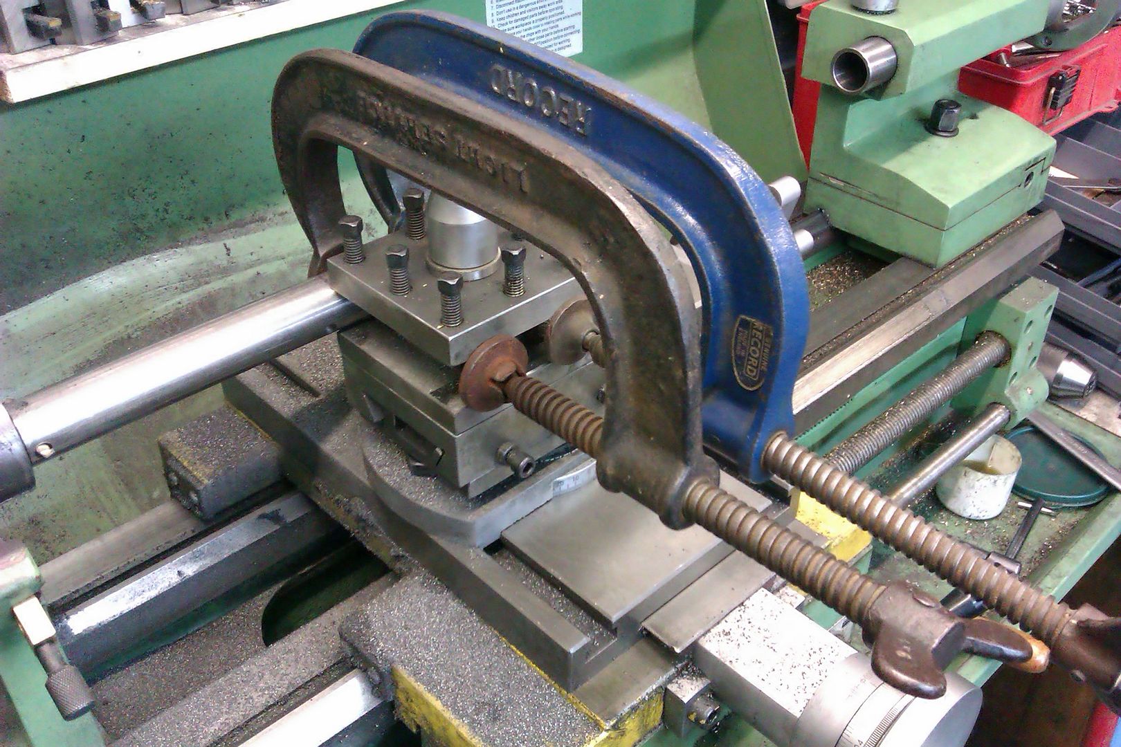
                  For a toolpost mounted bar you really need something solid, 30mm is the thickest one I have, this does not actually fit in either of my toolposts but reverting back to the supplied 4-way post I can use one sid eof that like a Vee block and clamp the bar to that. This is a smaller 25mm bar doing a cylinder liner 160mm long

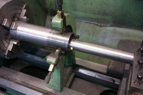
                  And this is the 30mm one being used between ctrs

                  A lot will depend on how easily you can mount the cylinder on the cross slide, it may prove easier to hold the bar than the work.

                  At 60mm bore you can reduce the length of a between ctrs one a bit as the live ctr will fit inside the work, also a between ctrs bar should go back in the same place.

                  Edited By JasonB on 23/01/2015 18:39:42

                  #177030
                  Fowlers Fury
                  Participant
                    @fowlersfury

                    After frustration with a 'simple' boring bar, I made one to the Geo Thomas design. It was well worth the effort, especially when using a micrometer to set an incremental increase in cutter radius. As the old boy wrote ~ the force on the cutting tool is not at 90 deg to the bar which aids producing a parallel bore.

                    #177033
                    Speedy Builder5
                    Participant
                      @speedybuilder5

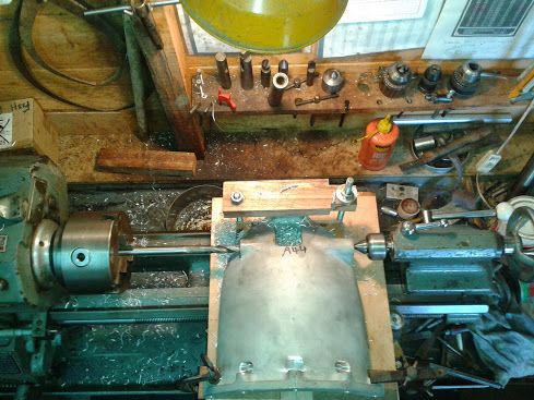
                      Hi Gordon, in-line boring is great if you can mount the cylinder block satisfactorily. This photo is of a vintage car clutch housing being in-line bored before through reaming 15mm diameter. on my Boxford Lathe The length of the bore was about 11" long, and the operation was completed with an extended reamer with a 'slip bush' to keep it aligned.clutchhousing.jpg
                      The photo shows drilling before line boring between centres. Note the simple mounting of the casting (aluminium) – just sitting on a sheet of plywood.

                      #177106
                      Gordon W
                      Participant
                        @gordonw

                        Thanks for the replies, I'm doing some thinking. This cylinder will have a mounting foot on one side and a lug on the other, stick welded.This was what got me thinking about between centers boring. My plan is to drill and bore roughly to about say 40mm dia. Weld up and let the stress work out, then finish bore to size. The exact bore does not matter ,can make piston to suit. I will have to make boring bars whatever way, none this sort of size. Also will need at least two B/Center bars, and a right fiddle adjusting the cutter every pass. My thinking is rough out in chuck then change to a b/centers bar for final cuts, and hope this will give a better finish . BTW this is for a model Robinson hot air engine. Just in the plannig as have not got roof fixed on w/shop yet. Not finished big fixed steady, never mind making boring bars.

                        #177128
                        Paul Lousick
                        Participant
                          @paullousick59116

                          Hi Gordon,

                          Your cylinder is only 150mm long with a 7.5mm wall thickness which should be fairly rigid if held in a chuck. (say 30m inside of the chuck with 120mm extending) Should not be a problem with a decent size boring bar.

                          I had to make a similar cylinder for my engine but from cast iron not steel and only had a 4mm wall thickness.

                          I bought a piece of hollow bar and rough turned it leaving the bore a couple of mm under size but left the wall thickness about 12mm. Then let the cast iron age for 2 months to relieve any internal stresses. Because the wall thickness was 12mm, I was able to hold it in a chuck without distorting the cylinder and machine the bore to the finished size. (less a thou or 2 to finish later with a hone).

                          I then turned end caps with a slight interference fit to each end of the cylinder. These end caps were drilled to allow me to turn the outside between centers.

                          Paul.

                          #177141
                          Nigel McBurney 1
                          Participant
                            @nigelmcburney1

                            I have tried both methods when reboring Blackstone stationary engine cylinders ,I bored a 4 hp cylinder on a roundhead master,using a large long between centres boring bar and using the T slots for mounting the steadies to secure the cylinder to the saddle,and a 2 hp cylinder mounted on the faceplate of a Colchester triumph via a tool post mounted boring bar, it was easier and quicker to bore the faceplate mounted cylinder,particularly measuring the bore,though in both cases the bore dimension was not critical as a new piston was cast and machined to suit the bore.In cases where the lathe is worn and not particularly accurate,the between centres boring bar has the advantage that tip of the boring tool describes a constant circle(ignoring tool wear) whereas a cylinder held in chuck or faceplate relies on how true the lathe bores.Setting up the work is far more tricky using the b/centres bar to ensure the new bore is square to the existing machined faces, there is also the problem that due to the length of the bar the tool will tend to chatter.When machining the cylinder on the faceplate I had to make a bored out sub plate between the face plate and cylinder so that the boring tool did not run into the faceplate.The 5 inch bore on the 4 hp cylinder was 17 inches long and over its working life the bore had worn conical by 2mm the bore at the crank end was near nominal ,the extreme wear was at the head end,this is due to the paraffin not completely vaporising in the hot bulb and diluting the oil,though it was 80 years old at the time,the piston also had .5mm wear.

                          Viewing 12 posts - 1 through 12 (of 12 total)
                          • Please log in to reply to this topic. Registering is free and easy using the links on the menu at the top of this page.

                          Advert

                          Latest Replies

                          Viewing 25 topics - 1 through 25 (of 25 total)
                          Viewing 25 topics - 1 through 25 (of 25 total)

                          View full reply list.

                          Advert

                          Newsletter Sign-up