VFD wiring

Advert

VFD wiring

Home Forums Electronics in the Workshop VFD wiring

Viewing 19 posts - 1 through 19 (of 19 total)
  • Author
    Posts
  • #633696
    John MC
    Participant
      @johnmc39344

      In a prevous thread I asked about matching a VFD to a motor. I have now run the motor (3ph) from a VFD (240v). All is well, the motor respond to the VFD inputs.

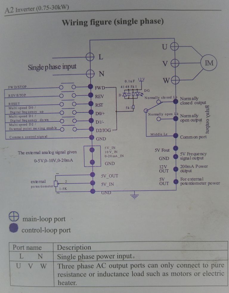
      I want to arrange a remote (from the VFD) control. The photo shows the wiring connections for doing this. Stop/start and forward/reverse with an emergency stop if possible

      I have some questions. Looking at the wiring diagram, can I have a single press button switch to stop/start before the forward/reverse switch, this being a toggle switch, on-off-on? That is to say select for/rev then switch on/off from a switch fitted before those two switches?

      For an emergency stop switch would it be okay to fit a normally closed stop switch (big red button!) before the stop/start in the previous paragraphs arrangement?

      Would I be correct in assuming that the switches shown in the diagram are latching, not momentary?

      John

      Advert
      #32325
      John MC
      Participant
        @johnmc39344
        #633700
        Martin Connelly
        Participant
          @martinconnelly55370

          There is usually only one switch for forward/reverse, open motor goes one way, closed it goes the other. Then a second switch can be used for run/stop as you require. This is the way I have my mill set up. My lathe is set to run forward or reverse from a single switch that is the original lever switch for the lathe.

          On some VFDs you can select if the switches are latching or momentary. In most cases the VFD will not start the motor if the run switch is on when the VFD is switched, on as a safety measure. This means a simple on off switch can be used safely as the run/stop switch.

          Martin C

          #633723
          John MC
          Participant
            @johnmc39344

            Photo I forgot to post!

            img_20230216_110804.jpg

            #633731
            Robert Atkinson 2
            Participant
              @robertatkinson2

              Hi John,

              As Martin says the inputs are normally programmable. The diagram does not really make sense. They have shown the symbol for momentary switches but assigned FWD (or REV) and stop to them This is contradictory. Also it's not clear whaat RST does.
              Normall the Emergency Stop has it's own input.
              What make and model is the VFD so we can find he manual?

              Robert.

              Edited By Robert Atkinson 2 on 16/02/2023 15:19:54

              #633733
              Peter Simpson 3
              Participant
                @petersimpson3

                I got my inverter up and running the other day. All works other than the Jog function When pushing the start button in Jog mode the lathe runs until the stop button is pressed. The jog function parameter is set to jog in the inverter but it does not "Jog".

                #633734
                Martin Connelly
                Participant
                  @martinconnelly55370

                  It looks like you have this VFD A2 VFD manual

                  The front panel has membrane switches so the unit is set up to start and stop when a membrane switch is pressed, you don't want to be standing there holding the switch down with your finger for hours. In order to use on/off switches you need to be able to change the way the VFD responds to an external input. Looking at the list of parameters this may be what settings Pn04 and Pn05 do. Setting an external switch for the run command (Pn04=2) and clockwise/anticlockwise enable (Pn05=3) could be what you need to do. Then an emergency stop would just require putting in series with the run/stop line to stop the motor but would not switch off the VFD. It should be easy to work out if this works the way you are hoping for.

                  Martin C

                  #633829
                  John MC
                  Participant
                    @johnmc39344

                    Thanks all for the replies. Martin C, thats the one, the manual seems to explain the settings for remote control.

                    The one thing I am not sure of is the swithces to (externally) control the device. As drawn in the circuit diagram they are momentary. Is that intentional or just poor interpretation of wiring diagram standards?

                    My thoughts are that these should be latching switches so as to provide a path for the selected parameter as other VFDs do.

                    John

                    #633832
                    Clive Brown 1
                    Participant
                      @clivebrown1

                      If the switches are latching, then several could be closed simultaneously unless, maybe, a rotary or change-over switch is used.

                      Other vfds don't necessarily use latching switches, the remote on my Teco 510 for example.

                      #633851
                      Martin Connelly
                      Participant
                        @martinconnelly55370

                        The external switch circuits are low voltage (12V) so I would just connect a wire to the ground terminal and touch the Run terminal with it to see what happens. If it only runs when the wire is connected then a normal on/off switch will work as you want. A second wire from ground to the Rev terminal should confirm that a forward/reverse switch will work the way you want as well. This is assuming you have set the parameters for an external switch.

                        Martin C

                        I will just add that for machines using a VFD they usually stop faster if the VFD is still powered up and the VFD is set to stop with a rapid ramp down and a braking resistor. It works like the DC brake now required in industry. Cutting power allows the motor and whatever is connected to it to coast to a stop without any active braking. This is why an emergency switch for a VFD powered machine needs to set the VFD to stop rather than cut power to the VFD.

                        Edited By Martin Connelly on 17/02/2023 11:19:10

                        #633862
                        Peter Sansom
                        Participant
                          @petersansom44767

                          I have one of these installed. The remote switches are not latching, they are expecting an ON/OFF switch and a FORWARD/REVERSE switch.

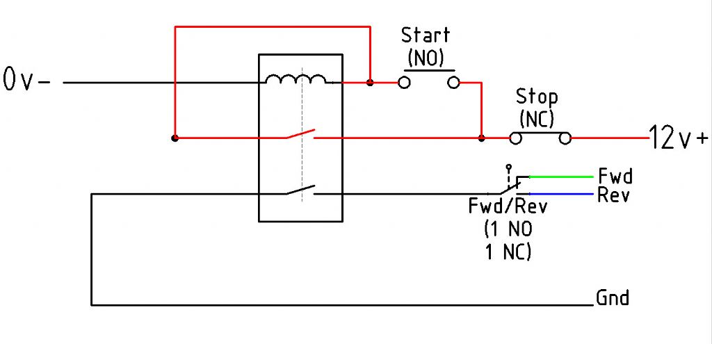
                          I got round the problem by adding a double pole relay where the coil is energised and latched by the START button and the STOP button breaks the power to the relay coil. One Pole of the relay is Forward and the other is Reverse. The FORWARD/REVERSE switch powers the correct relay pole. Output contacts of the relay are connected to the VFD Forward and reverse teminals.

                          There is no emergency stop on this VFD, but you can tweak the parameters for stopping by reducing the time delay.

                          #633965
                          John MC
                          Participant
                            @johnmc39344

                            Thanks for the replies. I still have the motor temporarily connected to the VFD so was about to do as Martin C suggested then the reply from Peter S appears confirming that the switches are momentary.

                            I have also found another forum thread about this particular VFD (via a google search). This thread has a useful list of parameter settings for remote operation.

                            I'm not ready to install the motor and VFD just yet, but when I am I'm sure there will be more question.

                            Again, thanks for the help and guidance.

                            John

                            #633983
                            John Hinkley
                            Participant
                              @johnhinkley26699

                              John,

                              I have responded to your PM and prepared a document for you. PM again and include your email address and I'll send it off.

                              John

                              #633986
                              Peter Sansom
                              Participant
                                @petersansom44767

                                Fwd to Fwd VFD,

                                Rev to Rev VFD

                                Gnd to Gnd Vfd

                                drill wiring.jpg

                                #633991
                                SillyOldDuffer
                                Moderator
                                  @sillyoldduffer
                                  Posted by Martin Connelly on 17/02/2023 11:11:22:

                                  The external switch circuits are low voltage (12V) so I would just connect a wire to the ground terminal and touch the Run terminal with it to see what happens. If it only runs when the wire is connected then a normal on/off switch will work as you want. A second wire from ground to the Rev terminal should confirm that a forward/reverse switch will work the way you want as well. This is assuming you have set the parameters for an external switch.

                                  Martin C

                                  +1 for a test, because the manual doesn't specifically say in words.

                                  However I read it as calling for Momentary Switches. Reason:

                                  • The diagram shows a two pole relay switch conventionally, suggesting the diagram's momentary switch symbols are deliberate.
                                  • Key pads, which are popular for controlling this type of device, are almost universally momentary.
                                  • The FWD and REV switches are both labelled dual function, FWD/STOP and REV/STOP. I think pressing FWD once starts the motor and pressing it again, stops it. Likewise, when the motor is running, pressing any of FWD, REV or RST once will stop the motor. All momentary, the latching is done by the controller, not mechanically
                                  • RST is the emergency stop. Press it once, and everything stops – no need for a latching switch
                                  • D0 and D1 which increase and decrease frequency (ie motor speed) are logically momentary functions, definitely not latching
                                  • D2 jog is also a momentary function, definitely not latching

                                  Best to confirm by experiment though – the manual might be misleading. Be careful not to poke wires into the power terminals, L N U V W.

                                  Dave

                                  Edited By SillyOldDuffer on 18/02/2023 11:40:21

                                  #636368
                                  John MC
                                  Participant
                                    @johnmc39344

                                    I now have the VFD wired up and working as I want. One thing though, I needed to use latching rather than the momentary switches shown in the wiring diagram.

                                    I found this out by experimenting as suggested, ultimately with permanent temporary(!) wiring to verify all was well with the VFD using latching switches.

                                    Any thoughts on this?

                                    I've looked at several VFD manfacturers installation instruction and have not come across another VFD that uses momentary switches (jog function excepted). Also no mention of shielding cabling to avoid stray signals in the manual, did that anyway, other maunfacturers always mention it.

                                    One final question, would it be possible to fit an emergency stop, Normally closed, latching. to the GND feed to the remote switches?

                                    John

                                    #636398
                                    old mart
                                    Participant
                                      @oldmart

                                      When I wired a Schneider VFD, the on off switches were momentary. These switches have a choice of connections, either on and momentarily off, or off and momentarily on, your choice. From the wiring diagram you need off and momentarily on. I also wired emergency off buttons, three of them in series which must have been on, (for a complete circuit) and latching off to break the circuit. Before latching, the emergency off switches work as momentary on to off which breaks the circuit long enough for the motor to stop, but if not properly latched, the on switch can restart the motor.


                                      https://inverterdrive.com/file/Schneider-ATV12-Easy-Start-Guide

                                      Edited By old mart on 06/03/2023 14:58:02

                                      #636507
                                      Peter Sansom
                                      Participant
                                        @petersansom44767

                                        The cheap Chinese VFD's seem to expect a latching switch, a relay can be used to turn the momentary switches into a latching Switches.

                                        I have a Bosch Rexroth VFD's to install and they can be configured to use latching switch or momentary contact switches.

                                        #636510
                                        Peter Simpson 3
                                        Participant
                                          @petersimpson3

                                          My recently purchased Colchester Bantam came with a Newton Teslar VFD system all wired up.. The remote pendant control box has all the usual Stop / Start. FWD / REV. Run / Jog.. Every thing works except the Jog button. It works just like the run button. I would assume that a parameter in the inverter needs setting to allow the Jog to run only when the Start button is depressed. I have looked through the IMO manual burt not sure which parameter needs changing..

                                        Viewing 19 posts - 1 through 19 (of 19 total)
                                        • Please log in to reply to this topic. Registering is free and easy using the links on the menu at the top of this page.

                                        Advert

                                        Latest Replies

                                        Viewing 25 topics - 1 through 25 (of 25 total)
                                        Viewing 25 topics - 1 through 25 (of 25 total)

                                        View full reply list.

                                        Advert

                                        Newsletter Sign-up