I am not an electrical guy in any shape or form but want to add a stepper motor to the Z Axis of my Warco WM18 Mill, and I need some help in sorting out the wiring. All I want a simple “On-Off-On” switch to select the up or down motion of the “Z” Axis. I plan to mount the switch on the mill’s control box in a small enclosure. I will use a NEMA 34 stepper motor with 12Nm torque driven by a S-350-60 PSU both of which I have already purchased.
The PSU has the Live, Neutral & Earth input connectors as well as the following connectors available: 3 off V+ and 3 off V-
The NEMA 34 has the following four wires available:
Black = A+ Green = A- Red = A+ Blue = A-
I also need to include a microswitch to limit the travel of the Z Axis when it reaches the top of the Z Axis.
So, how do I wire this all up without burning anything out?
You did not mention the stepper phase drive controller or a step/direction pulse generator, so I am assuming you don't know how steppers work – If I assume incorrectly, I apologise…
You need a DC power supply 20 to 40VDC or so at a few amps – The S350-60 is that PSU I think. Then you need a stepper drive controller – feed that with DC from the S350 supply.The Stepper controller has 4 wires out, 2 to each phase of the stepper motor – the 4 wires you mentioned.
Then you need a pulse generator that send pulses to the STEP input of the stepper controller. The controller then drives the 2 phase outputs as needed by the stepper motor. The pulse rate determines stepper rotational speed. The controller also has a direction input – logic HI makes the stepper go one way, logic LO , the other way..
So before you get to simple on-off-on and microswitches, you have to sort all the aforementioned goodies out first.
Lots of info through google, and we can all help here too.
Thanks Joseph – you are correct on not knowing how SMs work. I am a complete novice on electrical things, but I am having a go! I will check out your links. Many thanks.
Looks from the S-350 specification as if you've bought a power supply, in which case (as is usual), you also need a controller.
But I think there's a problem with the S-350-60, it has a 60V output which may make it difficult to source a controller.
A popular controller is the TB-6600, but this is max 42V and requires a pulse input to make the motor move, at a speed dependent on the pulse rate. They're good for microcontroller projects rather than simple wiring up.
There are alternatives that include speed control and reverse in a box like this but this example is max 30V. It may be possible find one that does 60V. The wiring is simple except for the limit switch. No problem using a microswitch to cut the power, but the problem then is how to restore power so the motor can be reversed out of trouble. Might be easier to wire the switch to a buzzer and position it to warn the operator to STOP NOW!
In the example, there are two green terminals marked + and -. Just run one wire from + to any of the three + terminals on the S350, and a second from – to any of the three – terminals on the PSU. The controller also has 4 terminals labelled A+, A-, B+ and B- that match the stepper motor.
I take your point about the S-350-60. I should have read more about it before ordering. It's going back to the seller now.
Now looking for a psu that will run the 'box' you linked to as I like that concept. Is 30v that max? So I should look for a 24v psu? or what would you suggest?
…
Yes, 24V at about 5A should be fine. This example is on Amazon is typical. It's from the same family as the one you bought, just less volts and amps to suit the motor and controller.
60V has the advantage of making the motor run a bit faster and less likely to miss steps, but it's harder to find controllers for high voltages. I'm sure they exist. For what you're doing 24V is more than adequate, or I'll eat my keyboard!
A NEMA 34 stepper will certainly be man enough to directly drive the X axis, it's what I have on my Chester Champion 20V which is equivalent. I am not so sure about the TB6600 based driver though. Although it appears to be adequate at 4 amps, from my experience, it gets extemely hot when driving a much smaller stepper drawing only a fraction of the four amps. The 34 size stepper is quite a beast, it might be a bit too much for the integrated pulse generator and driver that Dave (SOD) mentions.
That one also has an AC supply option. Or look at various suppliers on Amazon, eBay etc. Higher volts is better (though yours is a non-demanding application).
StepperOnline is another reputable supplier. Have a look for DM860T, this will handle 60 volts and plenty of grunt for a NEMA 34 stepper. I run my large steppers from a 40 VDC home made linear power supply that will easily handle high current peaks without tripping.
No need to send psu back. You need a dm860h or equivalent driver which will function perfectly with a 60 volt supply.These days about £40 each
These are the correct size for nema 34 steppers. I have 3 nema 34 motors running fine on my W18 size mill using these drivers. Take a look on the auction site for' longs motors'. Chinese as they all are but usually shipped from within U.K
6600 driver range are for nema 27 motors. Ok for X & Y axis bit under for Z but still okay
I assume that you only want to relieve yourself of manually winding the head up and down, in which case, a stepper motor is a bit of an overkill ? A concoction of a battery drill connected to the Z handle would give the same result.
If you use micro switch for the limits, you could have the stepper motor going at full speed and coming to a dead stop which could make the drive belt slip or other horrible noises.
You would need a soft stop as the limit switch was reached. If you are into programming ARDUINOs or other micro controllers, this can be good fun and would also allow you to "back out" from a micro switch stop that had been triggered. Also, if you used a micro controller, you could display distance travelled, feed speed and anything else you wanted to display. The accuracy of that would not be the same as a linear DRO, but fun all the same.
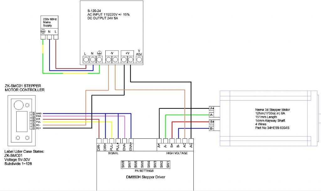
Making progress – I now have all below parts in my house and I am about to try and wire this all up.
So HELP – I am a numpty regarding electrics and attempts in the past led to a burning smell or a loud bang.
I want to avoid that this time so would some of you kind experts look at my proposed wiring diagram and tell if it is SAFE and won't burn or go bang please.
The very first thing to check before applying power is that the 110/240V switch is set to 240V if that is what you are running on. Otherwise everything looks good to go. You may get away with not connecting the enable wire.
I'm not sure why the dir, pul and ena positive sides are connected to the ground of the controller, I'd have thought it should be the negative sides? Presumably the PSU is a switched mode type that doesn't actually have the voltage switch that Martin mentioned, it just has a wides supply voltage range.
Slightly odd that the DC supply goes to the AC input on the stepper driver. Is that correct by the manual? It doesn't show a polarity so I guess the driver must have its own amps to isolate the input.
That particular driver can be fed AC or DC. If DC, minus is the end terminal, as shown in Alan's diagram. Unless I'm being stupid the rest of Alan's diagram is correct too.
The way the enables are connected depends on which way round the controller logic is set. (ON/OFF can be either 1,0 or 0,1) Not a problem if it's wired wrong, the motor just won't obey orders. Fixed by grounding the other way round, + rather than -.
The only diagram I could find for this controller did not show what the outputs are doing and did not show a recommended connection to a driver. I thought it may be a recommendation from the controller paperwork. The worst that can happen is nothing. The connections for the driver module show either the +ve terminals commoned together and connected to Vcc or the -ve terminals commoned together and connected to the ground terminal. In the absence of proof one way or the other try the wiring as shown. If it doesn't work then look at the driver module diagrams and try them instead.
Thank you Martin and John which prompted me to look again at my wiring diagram and noted a mistake, so I consulted the Driver manual and noted the AC input is 20 ~ 70 v AC and not DC as I had thought – phew!
Update diagram is below. I added a step down transformer (240vac to 24vac) for the driver power. I also checked the ground and have it correct – as shown in the circuit diagram from the manual.