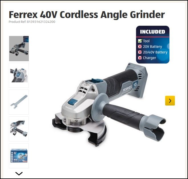
I have bought a £15 Ferrex battery grinder from Aldi with a view to removing the metal work head and fitting only the motor to another device.
This grinder uses a 40v battery and has a soft start but no speed control. I don't need the soft start since there will be no cutting disc or rotating parts exposed.
What I want to do is either junk the soft start and fit an independant speed control in it's place, or manually manipulate the soft start ramp to adjust the RPM with a speed pot or something. Here is the board and components that make up the soft start module:
The motor won't be under much load from it's retro-fitted duty, far less than when being used as an angle grinder. What I want to know is:
Does anyone know what method would be used normally to control the ramp, and could it be manipulated to work as a speed setting instead?
OR
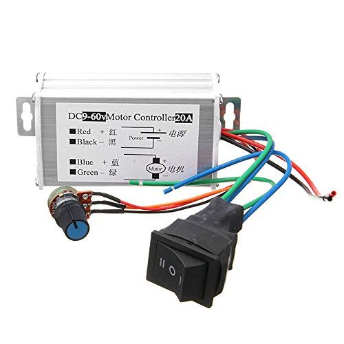
Can anyone suggest a suitable speed control that I can put between the 40V battery and motor to vary the speed?
Please I don't want any suggestions to go and buy a grinder with speed control most are an unsuitable shape to do the conversion and since this is an experiment I don't mind trashing a £15 grinder but I'd rather not spend much more on a named brand that I might end up scrapping.
I think it will be difficult to modify unless you can reverse engineer the circuit and take measurements with an oscilloscope. Looks like a mosfet power transistor used to switch the motor controlled by U3.
Probably easier to buy a speed controller from eBay as has been mentioned.
Looks like you may be ‘scraping’ the bottom of the barrel (or something else? .
I think I still have the speed controller from a mains voltage router, I finally burned out recently, if that might work at low voltage. You are welcome to it, if it helps. Most battery operated screwdrivers have trigger operated speed controllers – plenty of scrap ones around?
Does the 20/40V actually refer to the voltage – or the capacity? – never can tell with these adverts!
The 20/40v batteries are just two 20v batteries in one package. Some tools use only 20v, others like this one connect them in series for 40v. The underside of that board pictured above has a heavy PCB track linking B1+ to B2- to series them.
I don't think any battery screwdriver controller will do the job unless it could be used to switch the mosfset in PWM mode.
I have looked at some of the ebay/amazon offerings and so far there are none that are powerful enough yet small enough to fit inside the housing. I was kinda hoping that the soft-start works by sending a rapidly-lengthening PWM pulse to the mosfet and that I could somehow swap that output for one from a PWM chip but I guess my 'lectronics knowledge is too scant for that to be feasible.
It's not a deal breaker. The original device is fixed speed it's just 10x more flexible if it can be varied.
grinding off the identification of the controller chip is fairly common in consumer products (the big boys in consumer products have their chips identified with their own private marks) – it makes blatant (aka Chinese) copying a little more difficult tho sometimes with grazing light you may be able to read it tho usually the chip will only be available in batches of 10000’s
I would be at all surprised if the 8 leg chip with the label sanded off was the ubiquitous 555 timer. Operated in a mode where it generates a pulse train whose duty cycle is set by an external voltage that ramps up when you switch on to give the soft start. Pulses go to the gate of the MOSFET, the big diode is a flywheel diode on the motor. Some judicious 'scope work could test the theory. If it's right then you could just feed a voltage to the 555 for variable speed control.
Interesting John, I didn't realise that a 555 tier could send variable duty pulses I thought they were always 50% duty but variable frequency. I'm very weak on the subject though.
It’s conceivable that the chip is a micro, an ATtiny variety…the 4 pads may be the program connections…there’s 5v, MOSI, MISO AND GND….but no pads for Clock and Reset…,?
Don't know if it is even worth trying to make something…
I agree. The circuit almost certainly is a soft-start, but how it works is unknown and it includes an unidentified 8 pin chip that could be anything from an NE555 to a microcontroller. More trouble to understand and modify than it's worth when PWM speed controllers are inexpensive on amazon, ebay and others.
An ordinary PWM controller provides a sort of built-in soft start. If a switched pot is provided, turning the motor off also sets the pot to minimum speed. May not be ideal or completely fool-proof, but often a reasonable solution.
Motor I can see, Red and Black, and battery connections allong the bottom.
What are the markings nest to the wires on the PCB (the silkscreened white markings)?
The fact that the Orange and Blue wires go to the outside two of three connections that are enclosed in a rectangle on the silkscreen. This looks a lot like it was intended for a potentiometer which could be used for a variable speed option.
Trying to retrofit speed control to a battery angle grinder seems a total waste of time to me. There will be a shortage of room inside the body. Shame the Lidl one was not bought, both my 12V and 20V have the speed control as standard.
I have bought a £15 Ferrex battery grinder from Aldi with a view to removing the metal work head and fitting only the motor to another device.
–
–
–
Thanks
Pete.
If I understand your posting, it seems the only part of the grinder that you want to re-use is the motor, so what is it about the Aldi grinder that make the motor so ideal for whatever you are making?
Ian P
1. It's cheap enough so it's no problem if it's a failure or if I ruin it and have to get another;
2. The pinion and bearing are a match for the original motor.
Variable speed is not a must-have. The original device was fixed speed.