Switch wire up

Advert

Switch wire up

Home Forums Electronics in the Workshop Switch wire up

Viewing 12 posts - 1 through 12 (of 12 total)
  • Author
    Posts
  • #604406
    Chris Murphy
    Participant
      @chrismurphy94983

      cfbb71f5-46a3-4382-a270-7f76b21ad3d9.jpega15f3113-a7f7-44cb-b71c-36849ad3b88f.jpeg5a4b0516-dd2b-4514-ab05-95ccbf850a3c.jpegHi,

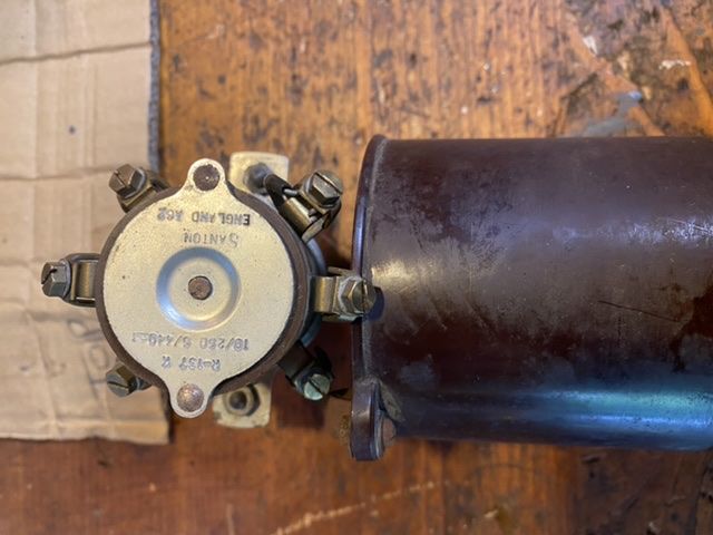
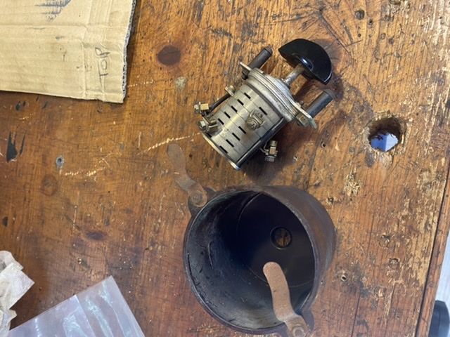
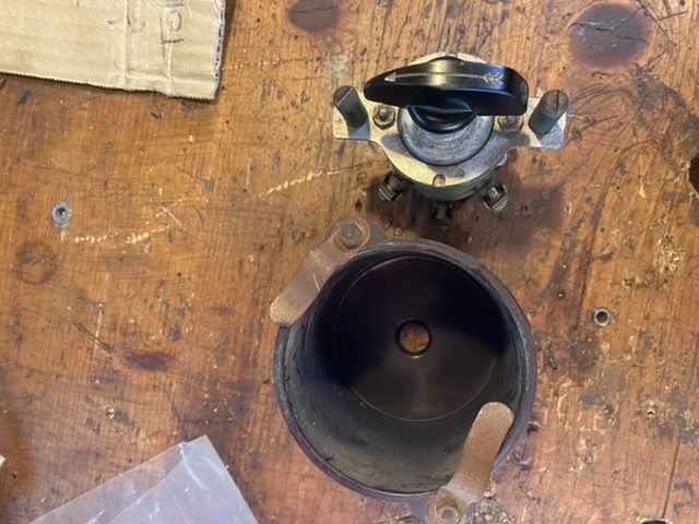
      does anyone know how I can wire this switch up to my ml7.

      I bought a Myford stand recently and this switch came with it, cfbb71f5-46a3-4382-a270-7f76b21ad3d9.jpegthey did say that it hadn’t been tested and weren’t sure wether it worked or not.

      has someone got a similar switch so you can let me know what Goes where.

      any help appreciated.

      thanks

      chris m……

      Advert
      #32270
      Chris Murphy
      Participant
        @chrismurphy94983
        #604407
        Chris Murphy
        Participant
          @chrismurphy94983

          Sorry forgot the last pica15f3113-a7f7-44cb-b71c-36849ad3b88f.jpeg

          Edited By JasonB on 05/07/2022 17:57:35

          #604408
          William Chitham
          Participant
            @williamchitham75949

            I can't give you any information specific to Myfords but my Boxford has a similar switch. When I bought it it was configured to switch a 3 phase motor but some of the contacts were all but burned out and it failed. However there were enough good bits in it to reconfigure and use to switch a VFD. If you can't figure out what goes where with a multimeter you may be able to work it out by dismantling it. One thing that may help is that not all of those terminals are necessarily going to connect to "in" or "out" wires – some may need to be ganged together with short pieces of wire.

            William.

            #604411
            Harry Wilkes
            Participant
              @harrywilkes58467

              Hi Chris can't answer your question and if no one come forward try the Myford group link

              https://groups.io/g/myfordlathes

              Cheers

              H

              #604413
              john fletcher 1
              Participant
                @johnfletcher1

                What make is your motor and can you identify which winding is the start and which is the run. As it says on the switch its a Santon, they are not easy to dismantle and reassemble, if you going to attempt to dismantle the switch do it in a large clear plastic bag, so that those little springs won't fly all over the place and get lost. I see on your picture there are 6 terminals which you need so you maybe lucky. I have an old Myford leaflet and it shows A1 is connected to one end of the start winding, the other end of that winding goes to one of the connection on the internal centrifugal switch, the other connection on the switch is connected to A2. F- is to the mains supply and so is F+. Run winding to a pair of unmarked pair of terminals either way round. Whilst that is a bit vague I hope might be useful. John

                #604416
                SillyOldDuffer
                Moderator
                  @sillyoldduffer

                  I guess it's a reversing switch, with either two settings (Forward and Reverse) or, much better three (Forward, Off, and Reverse). The Off position makes it less likely the clown at the controls will slam a fast spinning lathe straight into reverse without letting it stop first!

                  Three puzzles to solve:

                  1. Is the switch two, three or more positions?
                  2. How are the switch contacts arranged, and
                  3. Which wires in the motor need to be switched to reverse it. This depends on the type of motor fitted.

                  Experiment to answer Puzzle 1

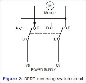
                  Puzzle 2: easiest way to work the switch out is with a multimeter or a bulb, battery and crocodile clips. I don't recommend taking the switch apart because of the risk of losing bits, or it not going back together properly. The basic reversing circuit is shown below. Your mission is to identify which terminals correspond to A,B,C,D,E & F

                  reverse1.jpg

                  Puzzle 3 will need expert help to identify the particular type of motor fitted. To start can you photograph the motor and the information plate please? Later, a photo of the wires inside the terminal box.

                  Before rushing in though, is it necessary to fit a reversing switch? Some lathes reverse with a tumbler gear, and others were never expected to run in reverse. In particular, beware if the chuck screws on rather than being bolted or cam-locked because cutting in reverse can undo them!

                  Reverse cutting is handy but not essential, and I suggest there's a great deal to learn and do before worrying about reversing motors. Low priority unless there's a specific reason reverse is needed. Miles down the list compared with learning how to turn and face Steel, Aluminium and Brass, plus drilling, boring, threading, 4jaw vs 3jaw vs face plate vs collets, dividing, eccentrics, tapers, milling in the lathe, steadies and years of other fun! Make a model horizontal steam engine and then get back to reverse, if you think it's still worthwhile.

                  Dave

                  #604421
                  noel shelley
                  Participant
                    @noelshelley55608

                    IF it is a santon single phase then the Myford hand book gives the following F- neutral, F+ live, A1 start winding, A2 start winding and the remaining 2 terminals are the run windings. The motor terminals very much depend on who and when the motor was made. If you have a brooks motor then it gets confusing as Sw A1 goes to Mtr Z!, Sw A2 goes to Mtr Z2 and Mtr A1 and A2 are the run windings ! Good Luck, Noel.

                    #604427
                    Chris Murphy
                    Participant
                      @chrismurphy94983

                      8441d688-d25b-456b-937a-48fd6e635ccb.jpegHi all,

                      thanks for trying to help.

                      im at a bit of a loss with electronics.

                      I thought I’d try to use the switch as it would look nice connected to the stand, not too bothered about reversing.

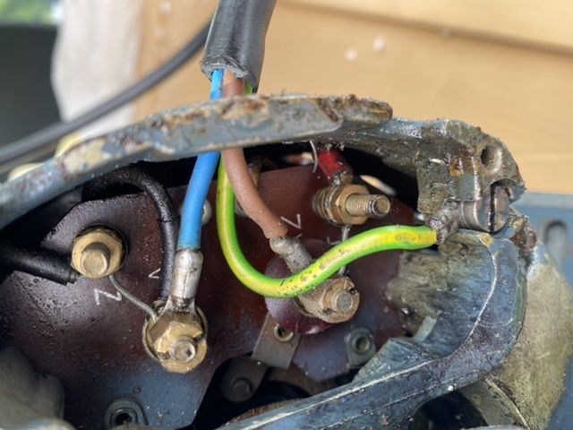
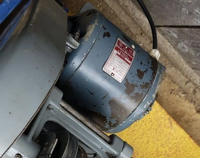
                      here are the pis of the motor plate and how it’s wired up, it a Compton Parkinson motor by the way.

                      cheers

                      chris m…..a80f4bcf-ad78-4f1e-be95-ec5a3371d95a.jpeg

                      #604430
                      duncan webster 1
                      Participant
                        @duncanwebster1

                        SOD 's diagram is only valid for a permanent magnet motor, which is not what the OP has. If reversing is not required then I'd put this switch aside and buy a motor starter with no volt release

                        #604435
                        noel shelley
                        Participant
                          @noelshelley55608

                          Inside the lid of the terminal box may be a wiring diagram ? It's a Brook motor, has it got a lump on the side we cannot see , A capacitor ? What are the letters you have on the terminal plate ? Z, A, AZ, T ? IT IS VITAL that the yellow wire is connected to earth, the screw in the corner IS the earth connection. Noel.

                          #604436
                          Les Jones 1
                          Participant
                            @lesjones1

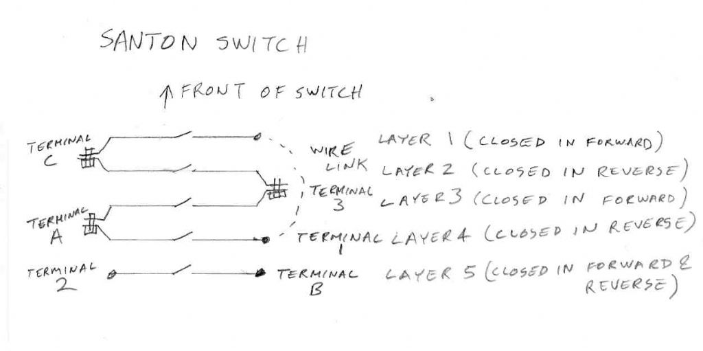
                            Here is some information on a Santon switch that someone was using with a Myford. It may not be the same as the Santon switch that you have but you can meter out your switch to see if the contact layout is the same as the one in my notes.

                            contact_layout.jpg

                            This is from a thread that was probably around 10/03/16 (When I uploaded the picture to the forum.) or 29/09/14. (The date of the file on my computer.)

                            These are the notes that I uploaded to the thread,

                            Information on Santon switch which is sometimes fitted to Myford lathes

                            This is how I understand the switch works.

                            Forward B to 2, C to 1, A to 3

                            Reverse B to 2, C to 3, A to 1


                            I have been looking at the way the switch works. There must be 5 contact sets. Each contact set is on a layer of the switch. I will call the front layer layer

                            1. Terminals C, 3, and A are actually connected to 2 layers each. (You can see the metal connections from 2 adjacent layers bent together.) Terminal C

                            goes to layers 1 & 2. Terminal 3 goes to layers 2 & 3. Terminal A goes to layers 3 & 4. The contact that I expected to be closed in the for forward position

                            of the switch (Terminals 3 and A)

                            Layer 1 Terminals C (and 1 via a wire link) (Closed in forward.)
                            Layer 2 Terminals C & 3 (Closed in reverse.)
                            Layer 3 Terminals A & 3 (Closed in forward.)
                            Layer 4 Terminals A & 1 (Closed in reverse.)
                            Layer 5 Terminals 2 & B (Closed in forward & reverse.)


                            Wires from motor to switch

                            Start R

                            Start S

                            Run U1

                            Run U2


                            Santon reversing switch connections.

                            1 To motor start terminal (R ?)

                            2 Live in

                            3 To motor start terminal (S ?)

                            A Live in

                            B To motor run terminal (R ?)

                            C | Neutral in
                            | To motor run terminal (U1 ?)

                            Where the above connection shows start terminal it means the start winding in series with the centrifugal switch and start capacitor.

                            Les.

                            Edited By Les Jones 1 on 05/07/2022 20:16:39

                          Viewing 12 posts - 1 through 12 (of 12 total)
                          • Please log in to reply to this topic. Registering is free and easy using the links on the menu at the top of this page.

                          Advert

                          Latest Replies

                          Viewing 25 topics - 1 through 25 (of 25 total)
                          Viewing 25 topics - 1 through 25 (of 25 total)

                          View full reply list.

                          Advert

                          Newsletter Sign-up