Is this 3 phase motor suitable for delta/VFD?

Advert

Is this 3 phase motor suitable for delta/VFD?

Home Forums Electronics in the Workshop Is this 3 phase motor suitable for delta/VFD?

Viewing 25 posts - 1 through 25 (of 25 total)
  • Author
    Posts
  • #32247
    choochoo_baloo
    Participant
      @choochoo_baloo
      Advert
      #591495
      choochoo_baloo
      Participant
        @choochoo_baloo

        I'm planning to convert my Senior M1 to VFD. Transwave's helpful "Converters and Inverters – layman's guide" is a lucid overview of the process, well worth a read.

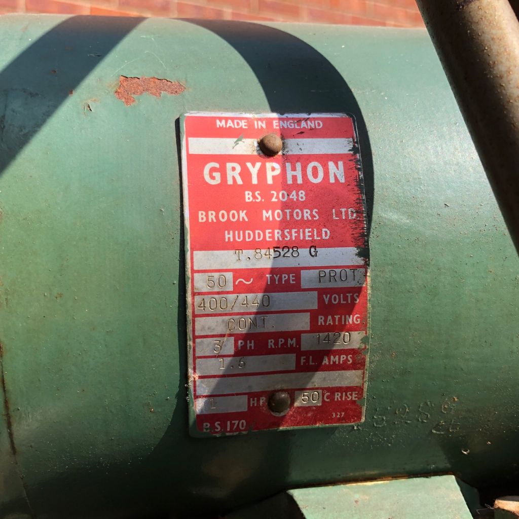
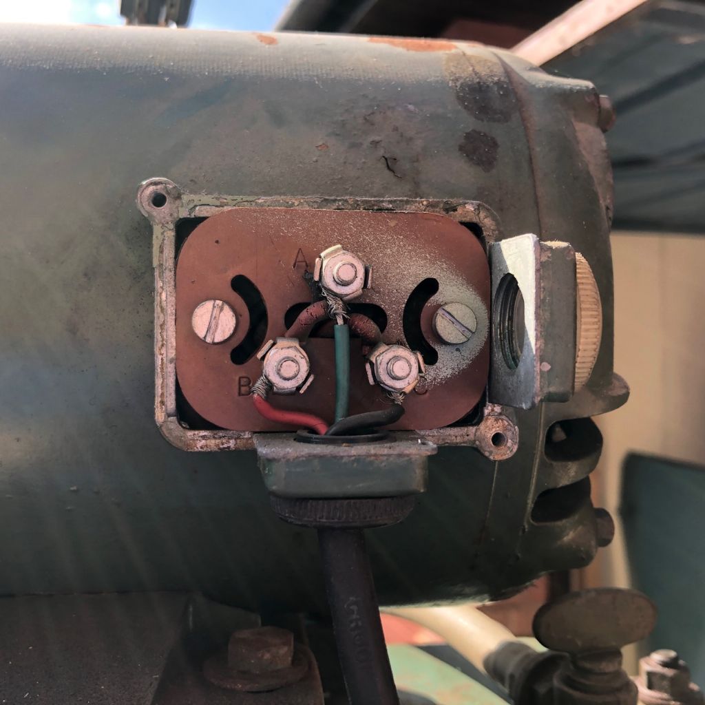
        BUT…the original Crompton 3ph motor states 400V and I'm wondering whether these connections can be changed to delta/240V as required by inverters. Why does it lack the {W2, U2, V2, U1, V1, W1} that I've read about? Perhaps hiding behind that fibreboard?

        (NB I can't get to the motor for the time being for a fiddle, so am relying on these old photos.)

        3ph_plate.jpg

        3ph_terminals.jpg

        #591500
        DC31k
        Participant
          @dc31k

          As the data plate states, and as the connector block shows, the motor was supplied for 400v connection only. This means the srar point, the commoned connection of the three coils, is inside the motor body. To enable 230v three phase, you have to dismantle it, locate the star point and bring out the three wires to a six terminal connector block. Some motors are easy to do, others more difficult. The only way to find out is to take it to pieces and look.

          #591512
          Martin Connelly
          Participant
            @martinconnelly55370

            Ask Transwave if a step up transformer is available or a 230/240 volt input 400 volt output VFD and what the cost would be. You may have the options of rooting out the star point, adding a transformer, getting a step up VFD or replacing the motor. You can then consider what is the best solution for you. There are probably videos on the internet of people accessing the star point.

            Martin C

            #591518
            Clive Foster
            Participant
              @clivefoster55965

              Having looked into using a step up transformer before I'd say its never worth it unless you happen to luck into something suitable. Allegedly such things can be found in some old fashioned welders.

              Seems to be a fairly low power motor, current stamping on the data plate appears to be 1 amp, so maybe one of the multiple output transformers on machine tools with a 240 tapping might do the deed. The Bridgeport one can, allegedly, be used in step up.

              If I recall correctly the Brook Gryphon motors put the star point on top of the windings so its easy to get at.

              If the application is fairly undemanding one of the 220 V in, 380 V out economically priced import VFD boxes may well be satisfactory. We very rarely drive our tools at anything approaching full power so the odds are that the various performance limitations inherent to making an affordable device won't show up.

              Clive

              #591522
              noel shelley
              Participant
                @noelshelley55608

                If all you want to do is run the motor at it's rated speed 1450rpm then a transwave converter will give you 400v but if you really want variable speed ie a VFD then rewiring to delta. I would try to rewire if you must as Brooks motors are amongst the best. Good luck Noel.

                #591529
                Andrew Tinsley
                Participant
                  @andrewtinsley63637

                  Have rewired a similar Brookes motor and found the star point where Clive said. Nothing to stop you running the motor as is with 240 volt 3 phase but power will be reduced. I have done this on a suds pump motor where the star point was well and truly buried.

                  Andrew.

                  #591537
                  SillyOldDuffer
                  Moderator
                    @sillyoldduffer
                    Posted by choochoo_baloo on 25/03/2022 02:59:04:

                    ,,,

                    the original Crompton 3ph motor states 400V and I'm wondering whether these connections can be changed to delta/240V as required by inverters. Why does it lack the {W2, U2, V2, U1, V1, W1} that I've read about? …

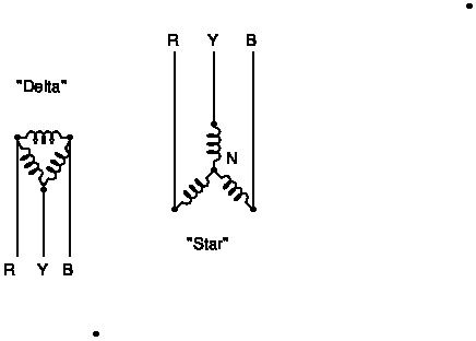
                    Three phase motors contain three windings (coils), that can be connected up in either of two configurations, Star or Delta:

                    stardelta1.jpg

                    On many motors, the ends of the three coils are brought out to the terminal box, ChooChoo's W2, U2, V2, U1, V1, W1, where W1 and W2 are the start and end of coil 'W'. etc. When this is done, the user can connect the motor in either star or delta. Star connected motors require 400V, delta needs 230V.

                    Unfortunately, not all motors provide full access to both ends of all the coils. Instead the connections are made inside the motor, not easily available to the user. ChooChoo's motor was sold for 400V service, with no intention it would ever be changed. However, it may be possible. When the motor is opened up to expose the windings, it's likely the star point (marked N above) is accessible. If so, break the connection and extend the 3 wires outside the motor so the coils can be reconnected in Delta in a terminal box.

                    Alternatively, it's recently become possible to buy affordable 230V input VFDs that produce 400V out to drive a star motor without modification. I'd be inclined to go that way because it's less work! When buying the VFD, it may be specified as 220/380V rather than 230/400V because most of the world is 220V based. Should be 'good enough'.

                    Usual Health and Safety warning when working with mains power, but be aware a 400V shock is much nastier than ordinary mains. Never work on live wiring and make sure the connections are understood etc.

                    Dave

                    #591541
                    Gary Wooding
                    Participant
                      @garywooding25363

                      choochoo:

                      My mill has a similar GRYPHON motor on the table feed (see my Centec album). It too is stamped 400/440v and had no provision for converting to 220v delta, so I stripped it, located the star-point (where 3 windings are joined together), split it and extended the wires out to the connector block. Re-assembled everything, connected the 6 wires into delta and it now runs happily on a 240v VFD. See some photos in my Centec album.

                      It wasn't difficult and was well worth doing.

                      #591543
                      Simon Williams 3
                      Participant
                        @simonwilliams3

                        Usual Health and Safety warning when working with mains power, but be aware a 400V shock is much nastier than ordinary mains. Never work on live wiring and make sure the connections are understood etc.

                        Dave

                        Sorry Dave, can't let that one pass.

                        400 volts (line to line) is the same thing as 230 volts (line to neutral).

                        Three phase motor suitable for 400 v line to line in star needs 230 volts line to line in delta so only 133 volts line to neutral. It's the line to neutral (earth) voltage that bites you, you'd have to try hard to grab two phases simultaneously.

                        However VSD outputs aren't necessarily symmetrical about earth.

                        #591553
                        SillyOldDuffer
                        Moderator
                          @sillyoldduffer
                          Posted by Simon Williams 3 on 25/03/2022 10:31:41:

                          Usual Health and Safety warning when working with mains power, but be aware a 400V shock is much nastier than ordinary mains. Never work on live wiring and make sure the connections are understood etc.

                          Dave

                          Sorry Dave, can't let that one pass.

                          400 volts (line to line) is the same thing as 230 volts (line to neutral).

                          Three phase motor suitable for 400 v line to line in star needs 230 volts line to line in delta so only 133 volts line to neutral. It's the line to neutral (earth) voltage that bites you, you'd have to try hard to grab two phases simultaneously.

                          However VSD outputs aren't necessarily symmetrical about earth.

                          Yeah, it's worth discussing, because I find it confusing too!

                          In my view '400 volts (line to line) is the same thing as 230 volts (line to neutral)' is correct in one sense, but not another.

                          In a star connected motor the neutral point is buried safely inside the machine. The neutral point inside the star isn't the same as mains neutral. Thus, a shock received from a high-voltage VFD is likely to be across two phases, that is 400V, not from one phase to neutral.

                          Domestic mains electrics connect neutral and earth together, so line-to-earth and line-to-neutral are at the same voltage, whilst neutral-to-ground is zero. This earthing arrangement is an effective safety feature because only one wire in the system is hot (live / line). A star motor and high voltage VFD is different.

                          I don't know what the line-to-ground voltage would be in a three wire 3-phase system, because in theory a pure 3-wire system has no neutral or earth. If a 3-wire system were completely isolated from earth and neutral throughout, then I think there'd be no voltage between any of the phases and earth. Don't try that at home folks, because the distribution system mixes 3-wire three phase and single-phase with earth and neutral together, so there's almost certainly some sort of return path from ground. Shocking!

                          Unlike the mains distribution system, a high-voltage VFD circuit might generate each phase in isolation, and also be isolated from the single-phase Line, Neutral and Earth, but I doubt it. Digital converters certainly don't work that way.

                          I suggest it's safer to assume a high-voltage VFD is a 400V hazard when working with one. As always, I'm happy to be put right if I'm wrong.

                          Dave

                          #591574
                          Mike Poole
                          Participant
                            @mikepoole82104

                            I doubt that any machine in the home workshop will have a motor large enough to be wound for 415v in Delta but large motors probably in excess of 7.5hp could well be wound for 415v in delta and 690v in star. A motor large enough to to benefit from star-delta starting will be wound for 415v in delta. At work we used some hoist motors that were on the cusp of being wound for being 415v or 230v in delta, as we ran them on a VFD then it was important to check the motor plate and set the VFD to match. These days it is likely that a small motor will be wound for 415v in star but it is not a certainty.
                            Mike

                            #591576
                            Niels Abildgaard
                            Participant
                              @nielsabildgaard33719

                              Old motors can smell awfull after a few minutes in company with a VFD.

                              I have tried it more than once.

                              Edited By Niels Abildgaard on 25/03/2022 17:10:49

                              #591579
                              old mart
                              Participant
                                @oldmart

                                You may be able to convert to delta, there's nothing to loose if you are careful with insulating and wiring. The alternative is a new motor to go with the VFD, Inverter Drive Supermarket sell both and also have their own "quick start guides" with some VFD'S that they sell. It makes the wiring and programming so easy. The only thing which could be a problem is that you might have problems with the motor shaft diameter and having to make an adaptor plate to mount the motor, I did with the Tom Senior light vertical.

                                **LINK**

                                #591582
                                choochoo_baloo
                                Participant
                                  @choochoo_baloo

                                  Just managed to sort out the mass of photos on my computer – just created a new "Tom Senior M1" album. Should make future questions more straightforward.

                                  Important point I forgot: I'm undertaking this to give my adjustable table feed rates via all the pulleys and gearboxes on the back of the column. 90% of the time I envisage using the powered S-head for the actual cutting. Does this constitute a 'light duty' application?

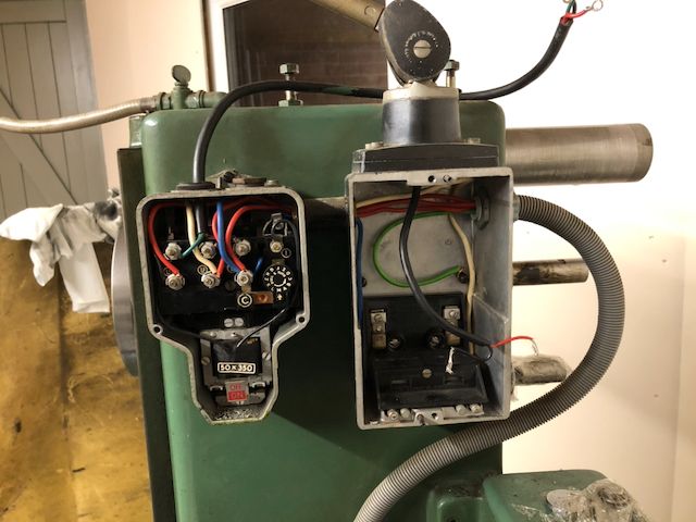
                                  Please see "3 phase column panels" photo, as below. The 3 phase supply is tapped off for the Lo-Vo lamp, with it then going through to the handsome Brook enclosure that had the ON&OFF buttons (cover removed). Can connections be used in some way?

                                  Then again the Transwave Layman's guide is clear that

                                  the VFD should be wired straight to the motor with no paraphernalia in between.

                                  3ph panels on column


                                  Edited By choochoo_baloo on 25/03/2022 18:23:00

                                  Edited By choochoo_baloo on 25/03/2022 18:31:53

                                  #591583
                                  choochoo_baloo
                                  Participant
                                    @choochoo_baloo

                                    One theoretical point a few of you have mentioned, I'd like clarity on:

                                    can supplying 240V 3ph (so approx half the rated 3ph voltage) actually harm an induction motor? Or does it simply reduce the torque across all supply freq's supplied by the VFD?

                                    NB: I'm quite happy with the physics in terms of their actual operation. The rotating B field induced by the 3 120deg stator winding pairs should behave as intended, just with lower magnitude when flux linking the rotor squirrel cage. Surely?

                                    #591584
                                    Anonymous
                                      Posted by choochoo_baloo on 25/03/2022 18:29:45:

                                      …can supplying 240V 3ph (so approx half the rated 3ph voltage) actually harm an induction motor?

                                      In a word – no. Running a 415V star connected motor with 240V phase to phase simply reduces currents, and hence torque and power, by the square root of 3.

                                      Andrew

                                      #591599
                                      choochoo_baloo
                                      Participant
                                        @choochoo_baloo
                                        Posted by Andrew Johnston on 25/03/2022 18:49:25:

                                        Posted by choochoo_baloo on 25/03/2022 18:29:45:

                                        …can supplying 240V 3ph (so approx half the rated 3ph voltage) actually harm an induction motor?

                                        In a word – no. Running a 415V star connected motor with 240V phase to phase simply reduces currents, and hence torque and power, by the square root of 3.

                                        Andrew

                                        Thanks Andrew. Good to know that all it would do is simply 'underpower' the motor.

                                        Just for my own understanding – only a minor academic point – wouldn't a star connection actually run at one third* of the motor rated power; whereas in delta each winding receives line voltages (415volts) and operates at full rated power?

                                        *using power equation: P /prop V^2 so P /prop (1/sqrt(3))^2 so P /prop (1/3)

                                        #591603
                                        Clive Foster
                                        Participant
                                          @clivefoster55965

                                          Chapter and verse about running a 415 V star connected motor off at 220 volt VFD here :- **LINK**

                                          https://inverterdrive.com/HowTo/240V-Supply-to-a-400V-AC-Motor/

                                          Short version is that its the same as a 415 V VFD up to approximately 29 Hz as there is sufficient voltage to drive enough current into the motor to generate rated torque. Above that there isn't enough voltage to drive the current it needs so torque falls off.

                                          If you have room for a larger motor it may well be cheaper to get a more powerful permanent star connected motor and accept the lower peak power speed than seek out a dual star / delta connection one of the right nominal power.

                                          Clive

                                          #591610
                                          old mart
                                          Participant
                                            @oldmart

                                            Your motor is only 1hp and running it from a VFD intended for delta would loose too much power. It is not recommended to have any switch between the VFD and the motor, even an emergency stop, as the VFD could be damaged. An emergency stop in the power supply would not stop the motor as quickly as the switching recommended by the VFD manufacturer.

                                            For the price of a Transwave converter, I could buy 2 motors and 2 Schneider VFD's, all the switchgear and wiring, with money left over.

                                            Edited By old mart on 25/03/2022 22:05:02

                                            #591636
                                            duncan webster 1
                                            Participant
                                              @duncanwebster1

                                              I once converted a Ferret grinder to run on single phase. The motor manufacturers warned against running older 3 phase motors on vfd, something to do with insulation I think. I used Steinmetz connection, but still had to dig out the star point. Not difficult, but you need to make sure it is safe afterwards

                                              #591650
                                              SillyOldDuffer
                                              Moderator
                                                @sillyoldduffer
                                                Posted by duncan webster on 26/03/2022 10:19:25:

                                                … The motor manufacturers warned against running older 3 phase motors on vfd, something to do with insulation I think …

                                                Driving electric motors made before 1967 with a VFD is a bit risky.

                                                I know the forum likes to believe ancient British electric motors are far better than any modern foreign rubbish. But get real! Although old British motors were well-made they were limited by the technology of the time, and don't forget old age and damp storage does them no favours.

                                                Two reasons a VFD might damage an old motor:

                                                • Inferior Insulation. The enamel used to insulate magnet wire has improved considerably over the years. Old enamels aren't as electrically, physically or thermally robust as the later ones.
                                                  • The first enamels were only good for about 80°C, soon improved to 100°C rising to 120°C around WW2, then 140°C during the 1950's. Modern enamels can take at least 180°C and some motors run at about 220°C.
                                                  • Cracks and bubbles were a serious problem in older enamels. Liquid enamel has to be carefully applied to bare copper wire because the dried layer can be flawed by bubbles, thin areas, and cracks caused by drying and winding the wire. Modern enamels are formulated to reduce the risk. Old magnet wire suffers because age and heat cycles tend to worsen the minor insulation flaws introduced by imperfect manufacturing methods. Damp makes flaws physically worse and much reduces the insulation's effectiveness overall. Much damage is caused when flawed insulation flashes over: magic smoke and the motor has to be rewired.
                                                • Bearings. For many decades, bearing makers received persistent complaints that the bearings used in electric motors often wore out quickly. The cause was eventually traced to leakage currents earthing through the bearings. The current caused tiny sparks that eroded the bearing surface. Once identified, the problem was easily fixed by slightly altering the motor design. Motors made after 1967 are highly unlikely to have this fault. However, if an old motor is discharging through the bearing, the sparks are made much worse by spikey VFD waveforms.

                                                1967 is the year after which the bearing problem was universally fixed and all motors were wound with modern enamel magnet wire.

                                                Does it matter? Maybe not. Weak insulation and tiny sparks inside the bearings are unlikely to cause an instant bleeding obvious failure.

                                                Bearing damage might never show up in a home-workshop and there's a reasonable chance even ancient insulation will be 'good enough' for a VFD. Problems are more likely to show up after many hours of operation than as an instant spectacular fail.

                                                I wouldn't go out of my way to fit an old electric motor, but if I had one to hand I'd dry it out carefully before using it. The worst that can happen is having to replace the old banger with a new one!

                                                Dave

                                                #591678
                                                Robert Atkinson 2
                                                Participant
                                                  @robertatkinson2

                                                  A 415V Star connected motor running on a UK light industrial 3 phase supply will have 240 V between each supply terminal and ground and 415 V between phases. (the ratio between the voltages is the square root of the number of phases, sqrt3 or 1.732 for 3 phase). The supply transformer will be connected Star with the common point connected to ground and the neutral conductor. This allows both single and 3 phase loads.
                                                  If you re-wire motor to Delta to run on a VFD the voltage between terminals will be 240 V (at 100% speed. At lower speeds it will be lower and higher speeds higher voltage).
                                                  The voltage to ground is harder to define.
                                                  There is normally no transformer at the output of a VFD, just semconductors switches to a DC supply of around 400 V (derived from the incoming single phase supply) so no defined AC path to ground. If everything is balanced phase phase and phase to ground the voltage should be 240 / sqr3 = 138 V. In reality it is likely to be a combination of DC voltage and "spikes" up to several hundred Volts.
                                                  The output of a VFD is almost always more hazardous vlotage wise than the output. Even using normal Thmultimeters on them is not recommended as the voltage waveform, spikes and harmonics can damage them.
                                                  These spikes and harmonics are other charateristics that can cause a VFD to damage older motors.

                                                  #591686
                                                  john fletcher 1
                                                  Participant
                                                    @johnfletcher1

                                                    In the past 3 or 4 years some one on this forum published am excellent article, with good clear pictures on how he located the Star point and brought out 3 extra wires into his motor terminal box. I have done the conversion for my friends, all on older motors, and as yet to hear of a failure, they bought their inverters via ebay and again not heard of a failure, could be they are just lucky ! I have an insulation tester up 1000volts which I used to give the motors a test before use. Have a go, you have not much to lose, you need to look out for a lump in the windings area which needs to be carefully opened up, and three wires attached. I used three different coloured wires for identification purposes, fibre glass insulation tube and heat shrink and a small amount of resin is readily available via ebay. Best of luck and let us know how you get on. John

                                                    #591718
                                                    Anonymous
                                                      Posted by choochoo_baloo on 25/03/2022 19:59:02:

                                                      …wouldn't a star connection actually run at one third* of the motor rated power…

                                                      I was thinking in terms of mechanical output power:

                                                      Power = torque x angular velocity

                                                      Assuming both voltages are at 50Hz the angular velocity is constant. The voltage reduced by the square root of 3 leads to phase currents reduced by the same. To a first approximation the torque is proportional to the phase current. So the torque, and hence power, is reduced by the same factor, ie, the square root of 3.

                                                      Andrew

                                                    Viewing 25 posts - 1 through 25 (of 25 total)
                                                    • Please log in to reply to this topic. Registering is free and easy using the links on the menu at the top of this page.

                                                    Advert

                                                    Latest Replies

                                                    Viewing 25 topics - 1 through 25 (of 25 total)
                                                    Viewing 25 topics - 1 through 25 (of 25 total)

                                                    View full reply list.

                                                    Advert

                                                    Newsletter Sign-up