“Angel eye” wiring colour code

Advert

“Angel eye” wiring colour code

Home Forums Electronics in the Workshop “Angel eye” wiring colour code

Viewing 25 posts - 1 through 25 (of 35 total)
  • Author
    Posts
  • #32240
    John Hinkley
    Participant
      @johnhinkley26699
      Advert
      #588063
      John Hinkley
      Participant
        @johnhinkley26699

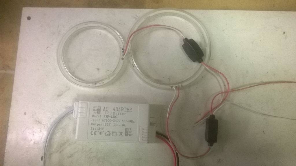
        With my latest project completed and 'in the can', my thoughts have turned to preventing the Devil from making work for my idle hands. To that end, I have purchased a couple of 'angel eye' LED rings and a power supply with a view to mounting one, or both, concentrically around the quill of my mill. So far, so good. Here's what I've got:

        angel eye group

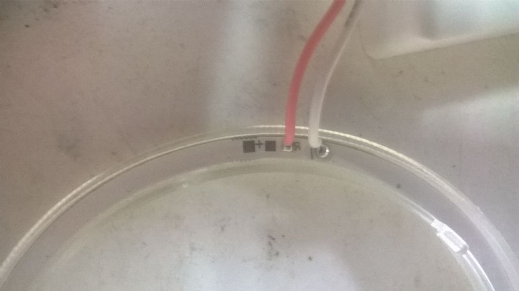
        This is as good a close-up as I can get of the connections:

        connection close-up

        Before I damage the LEDs, can I ask those with more expertise with electrics than me, to advise whether I am correct in assuming that the pink wire is the positive and the white is negative?

        The inline black capsule is described as a voltage regulator for 12V operation. Is this necessary with the pictured power supply?

        Hoping for some illuminating smiley answers!

        John

        #588084
        not done it yet
        Participant
          @notdoneityet

          Thry are diodes. Diodes only pass current in one direction. They will, of course, have a maximum reverse voltage which they can accommodate. They also have a maximum current rating, beyond which they will overheat and thermally run away.

          Does that help?

          Edited By not done it yet on 04/03/2022 10:34:54

          #588092
          Circlip
          Participant
            @circlip

            Isn't there a clue printed on the white box John? Think it shows the input and output connections otherwise contact the supplier. Unlike international thread sizes (Don't even go there) there doesn't seem to be one for far eastern electronics manufacture.

            Regards Ian.

            #588098
            John Doe 2
            Participant
              @johndoe2

              Get an AAA or AA battery and briefly touch the LED ring leads onto the battery, red one end, white on the other.

              Whichever way round the LED lights, the lead on the top of the battery is the positive, the lead on the flat bottom of the battery the negative.

              With a 1.5V AA/AAA battery, you will not do any harm connecting it the wrong way round for a few seconds.


              Edit: oh, hang on, just noticed the bit about the black in-line regulators. You won't get 1.5V through those, so will need to desolder or piggyback directly onto the LED rings from your AA/AAA battery with some spare wire.

              The in-line regulators are very odd, not seen that before. Unless you have test gear, and not knowing anything about the white brick's quality or provenance, you should probably keep the black regulators in circuit in the final build.

              I notice that the white brick's 12V output has a black lead on the +ve and a red lead on the -ve, so you are wise to be cautious. 

              Edited By John Doe 2 on 04/03/2022 11:27:40

              #588102
              John Hinkley
              Participant
                @johnhinkley26699

                Thanks all.

                Ndiy. Thanks, but doesn't determine which is the positive line.

                Ian, it's the angel eyes' connections that I'm querying, the power supply is clearly marked + and – and the output wires follow convention in being red and black.

                John Doe2. I'll give your suggestion a try when the rain stops and post the findings for the benefit of others encountering the same dilemma.

                John

                #588103
                Steambuff
                Participant
                  @steambuff

                  Don't assume anything …. Why not use a Multi-Meter to measure the voltage on the LED contacts …. It will read positive one way (The Red +ve lead will be on the positive LED terminal) and negative the other

                  #588106
                  peak4
                  Participant
                    @peak4

                    I've just tried mine on a bench current limiting power supply I built years ago.

                    Pink is +ve and it didn't start to light up until I hit about 6V

                    Bill

                    #588110
                    Anonymous

                      Forward drop for white LEDs is generally 3-4V, plus a drop across a series resistor, makes 6V about right.

                      Andrew

                      #588117
                      Circlip
                      Participant
                        @circlip

                        Just as another clue. If you look at the black boxes, they seem to be a standard design that the two halves snap together. When shortening the lead to supply a dash cam, it was easy to unsnap them and its easy to determine + and -.

                        Regards Ian.

                        #588130
                        John Hinkley
                        Participant
                          @johnhinkley26699

                          Once again, thanks to all.

                          I have a variable voltage output power supply so I'll try gradually increasing the voltage with that, having first tried to unsnap the regulator boxes. Progress!

                          John

                          #588132
                          Jouke van der Veen
                          Participant
                            @joukevanderveen72935

                            I bought the same light source for my milling column 2 years ago

                            Intention was to place the white power supply box in an earthed metal case at the back of the column.

                            Until now I did not finish that because I am a bit concerned about earth. Be aware that you connect the primary leads of the white box to 230V. At the secondary side it is connected to the led ring. The content of the white box is not from high standard and how certain can you be that never 230V comes through in case of malfunctioning?

                            #588133
                            Robert Butler
                            Participant
                              @robertbutler92161

                              The Angel Eyes are marked (although not too clearly) + & –

                              Robert Butler

                              #588146
                              John Hinkley
                              Participant
                                @johnhinkley26699

                                All sorted. Unsnapped the voltage regulator box, only to find some bits of electronic magic soldered to a tiny PCB with no useful lettering. Resorted to connecting the leads to the power supply in what I believed to be the correct orientation i.e. pink +ve, white -ve. Turns out that was right but the eyes gave off no light until the voltage reached 9V DC with the voltage regulator in use, so perhaps that's the reason for the slightly hgher voltage than expected being needed.

                                Now to fit them to the mill.

                                Thanks, again for the input, chaps.

                                John


                                Edited By John Hinkley on 04/03/2022 14:15:11

                                #588153
                                Jouke van der Veen
                                Participant
                                  @joukevanderveen72935

                                  LED’s in the ring must be connected in series, therefore required voltage is higher than, let’s say, 3.3 Volts.

                                  You read 12V on the output of the “power supply”.

                                  Be careful and stay save. I would place the tiny white box with that tiny PCB and CE-mark on it in an earthed box and still then you can not be sure that 230V will never escape from that. Primary and secondary tracks on that tiny PCB are not far away from each other I expect.

                                  #588156
                                  Neil Wyatt
                                  Moderator
                                    @neilwyatt
                                    Posted by John Doe 2 on 04/03/2022 11:02:27:

                                    Get an AAA or AA battery and briefly touch the LED ring leads onto the battery, red one end, white on the other.

                                    Whichever way round the LED lights, the lead on the top of the battery is the positive, the lead on the flat bottom of the battery the negative.

                                    With a 1.5V AA/AAA battery, you will not do any harm connecting it the wrong way round for a few seconds.

                                    You need three 1.5 batteries to light a white LED.

                                    #588161
                                    John Hinkley
                                    Participant
                                      @johnhinkley26699

                                      Jouke,

                                      Your warnings are duly noted. I intend to test various arrangements of wiring on the bench, firstly in parallel, both with and without the voltage regulators. If they go bang, I'll sweep up the ashes and start again. If I go bang, someone else will have to sweep up the ashes!

                                      John

                                      #588166
                                      Alan Wood 4
                                      Participant
                                        @alanwood4

                                        As already confirmed the white is negative and there is a '-' sign next to the connection to the ring. This is the ground plane on the back of the light under the white silk screen. Positive terminal has a '+' and the red wire. You can ignore the switching PSU and feed in direct to the ring at around 9V to get full brightness. Likewise the switcher will probably need at least 10V for full brightness. Depending on diameter the rings pull circa 200mA.

                                        I would recommend removing the 'bezel' to get a more uniform light. The bezel is just superglued in place and easily cracks free.

                                        I would also recommend not mounting the light concentrically but instead if you can have an eccentric offset. When you are working with very small tooling the 'chuck' will cast a close in shadow and if concentric mounted this shadow will be frustratingly even around where you are aiming.

                                        I have a Fusion 360 file that accommodates various ring diameters with various quill diameters to allow the mounting body to be 3D printed. Let me know if you want a STEP file to suit your dimensions.

                                        #588168
                                        Georgineer
                                        Participant
                                          @georgineer
                                          Posted by Neil Wyatt on 04/03/2022 15:16:30:

                                          You need three 1.5 batteries to light a white LED.

                                          That may depend on the particular white LED. I routinely test them with a 3 volt lithium coin cell, and I have a string of battery operated white LEDs (from Ikea) which run off 3 volts.

                                          George

                                          #588170
                                          John Hinkley
                                          Participant
                                            @johnhinkley26699

                                            Alan,

                                            Thanks for the info and guidance on the rings. Likewise, I appreciate the offer of the STEP file but I don't have a 3D printer. I do, however, have a 3D router, so I'll be pressing that into use and I'm currently drawing the mounting plate to suit, such that I can utilise the built-in lugs to clip it/them to the plate.

                                            When you refer to the switching psu, are you meaning the boxes that are called voltage regulators by the suppliers, or the power supply in the white box?

                                            John

                                            #588177
                                            Alan Wood 4
                                            Participant
                                              @alanwood4

                                              Sorry to confuse John.

                                              The device in the black box that hangs off the ring light is a switching regulator. It chops the incoming DC from the car electrics and transforms it down to the voltage required by the ring. Being a switching regulator it is more efficient and there is less heat created than there would be using a linear regulator.

                                              Here is a link to my blog showing the design. which shows the Fusion model and the offset nature. The trough is for the wiring connection to the ring. The ring gets hot glued in place and the trough filled to act as a cable clamp.

                                              The three tapped holes are for nylon mounting screws. These holes and threads are modelled in the 3D print.

                                              I usually stick aluminium foil on the lower surface using double sided tape. This increases the reflectivity.

                                              I also replace the supplied black box with a 3D printed larger size version which has a 2.1mm DC socket for the external supply. I also glue a magnet to this box so it can be latched onto adjacent metalwork.

                                              I hope that gives you some help.

                                              Kind regards

                                              Alan

                                              #588199
                                              Neil Wyatt
                                              Moderator
                                                @neilwyatt
                                                Posted by Georgineer on 04/03/2022 16:57:47:

                                                Posted by Neil Wyatt on 04/03/2022 15:16:30:

                                                You need three 1.5 batteries to light a white LED.

                                                That may depend on the particular white LED. I routinely test them with a 3 volt lithium coin cell, and I have a string of battery operated white LEDs (from Ikea) which run off 3 volts.

                                                George

                                                When fresh, these are usually 3.7 volts, which is enough. 2 AAs usually isn't quite enough.

                                                Neil

                                                #588205
                                                duncan webster 1
                                                Participant
                                                  @duncanwebster1

                                                  My angel eyes appear to consist of lots of sets of 3 LEDs each set with its own resistor, so you'd need quite a bit more than a AA battery. However mine doesn't look exactly the same as the OP's

                                                  #589094
                                                  John Hinkley
                                                  Participant
                                                    @johnhinkley26699

                                                    With the wiring sorted, I have moved on to production of the two halves of the mount. My design was developed in Alibre Atom to a stage where I was satisfied that I couldn't make any more mistakes and the time came to commit router to material.

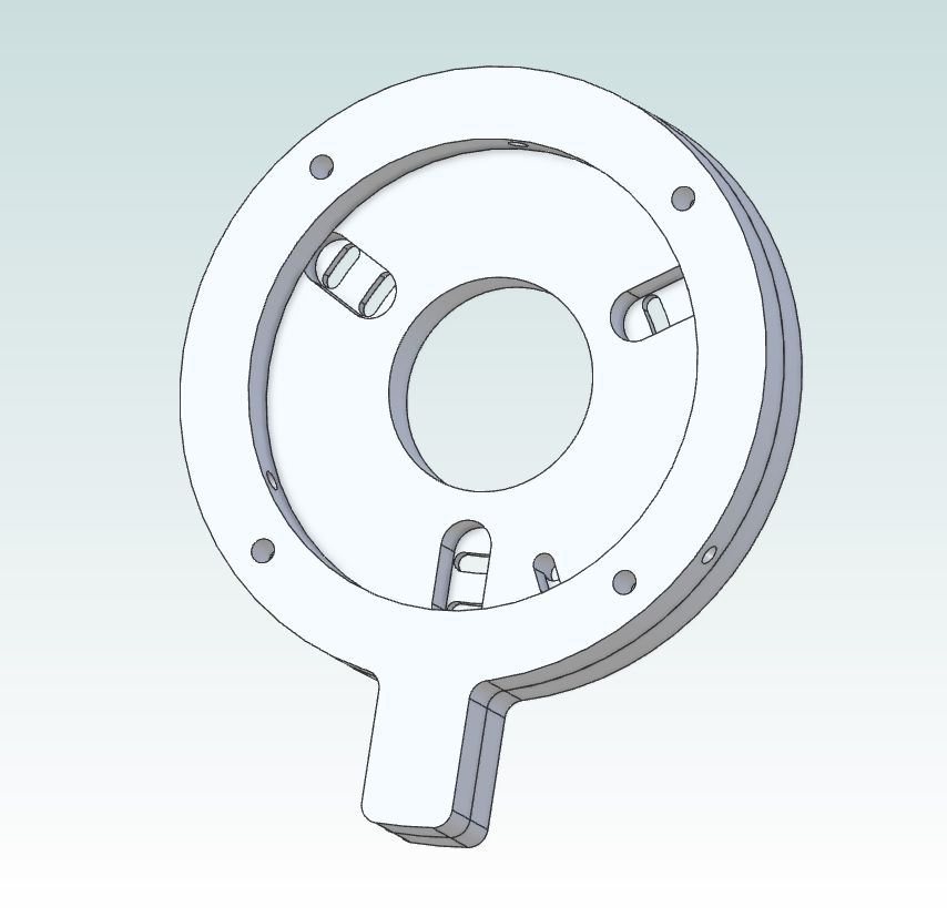
                                                    This is the final design that I came up with:

                                                    Mount design in Alibre

                                                    That's the view of the upper surfaces.

                                                    That translated into routed components to which I have mounted the LED fittings. I am at present awaiting the arrival of some 2-core flexible cable by post in order to complete the installation. There seems to be a local shortage of 2-core in my vicinity, unless you want to buy it by the drum. I don't, so ebay it is.

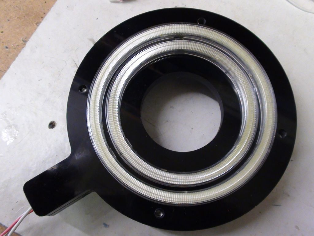
                                                    All fitted together and raring to go:

                                                    Angel eyes fitted to mounting.

                                                    That should give an impressive amount light and, if the warnings that I've ignored turn out to be well-founded, some equally impressive shadows on the cutter! Time will tell.

                                                    John

                                                    Edited for basic spelling mistake.


                                                    Edited By John Hinkley on 10/03/2022 10:45:54

                                                    #589108
                                                    Henry Brown
                                                    Participant
                                                      @henrybrown95529

                                                      Been following this with interest John, looking forward to the first trial!

                                                    Viewing 25 posts - 1 through 25 (of 35 total)
                                                    • Please log in to reply to this topic. Registering is free and easy using the links on the menu at the top of this page.

                                                    Advert

                                                    Latest Replies

                                                    Viewing 25 topics - 1 through 25 (of 25 total)
                                                    Viewing 25 topics - 1 through 25 (of 25 total)

                                                    View full reply list.

                                                    Advert

                                                    Newsletter Sign-up