Inverter connection problems

Advert

Inverter connection problems

Home Forums Electronics in the Workshop Inverter connection problems

Viewing 10 posts - 1 through 10 (of 10 total)
  • Author
    Posts
  • #32145
    Zan
    Participant
      @zan

      Bridgeport two speed motor and failed inverters

      Advert
      #500558
      Zan
      Participant
        @zan

        Single to 3 phase inverter problem

        I converted my Bridgeport to 240v in 2005. I ripped out most of the electrics in the control box and replaced the contractors . The inverter was purchased on eBay

        The motor was wired up as on the plate for low speed, which at the time I took to be 240 v (Probably not correct). The machine ran so I didn’t try any other connections. I used the varispeed on the 2JB head and ran the inverter at 50 Hz. The motor is two speed when running on 440 v 3phase and it has 9 wires.

        The inverter failed in 2009 and was replaced, but when purchasing the new one I was informed the old one could be repaired, at a cost of £20 a capacitor was replaced by them and it worked! The engineer commented that it was a very old inverter. I sold it.

        Now the 2009 inverter has failed Of course it was in the middle of an important job! All the ancillary electrics work ok

        So some investigation was needed. It seems I wired the motor to a choc block as in fig. 1 from the motor plate as shown in fig.2. It seems that this connection as shown in Wikipedia  is a modified star as shown in fig 3. As the motor should have been wired in delta as in fig 4 it should not have run at all!..

        But here is the conundrum, this diagram shows 6 coils so there should be 12 wires not 9. Some must be connected internally, or is it that I just don’t understand the workings of the two speed motor.

        fig 5 shows the coil resistance at 2.4 ohms for all but 7-9 and 7-8 @ 4.1 ohms

        I have tried unsuccessfully to sort out the diagram to account for this and the grey matter is spinning! I do not know what the colour coding means on the 9 motor wires

        It is the inverter which has failed , I connected it to my drill motor ( 3 phase as well) and it just jigged back and forward even with u,v &w interchanged

        I will probably get an upto date vector inverter rather than a straight VFD which will cost considerably more.

        In February this year, I had to replace a part in the head and made the mistake of switching the rotary switsc from forward to reverse on initial testing. This I know is a big Nono the machine worked ok, but it was noticeable that for a while the motor seemed a bit hesitant to start but it has been worked hard during lockdown.

        I don’t want to cook another inverter , so can anybody help with the connections please . I have viewed a lot of manuals and wiring diagrams, but none seem to match my setup.

        c480fb7f-1df8-4be3-8239-83c7619db336.jpegThanks.

        Edited By Zan on 10/10/2020 16:07:00

        #500559
        Zan
        Participant
          @zan

          It seems the left of the diagram fig 1 has been cropped. The connections from the top left are

          6

          4 blue

          9 red

          3 blue

          #500563
          John Rudd
          Participant
            @johnrudd16576

            image.jpegDahlander motor wiring……

            Best if you can identify each set of windings using a meter, so you end up with all the wires identified. Then connect them as the sketches….

            #500564
            Zan
            Participant
              @zan

              Thanks I was using something similar, problem is which wires are which, I have only 9 wires not 12 so which coil is where?

              #500569
              SillyOldDuffer
              Moderator
                @sillyoldduffer
                Posted by Zan on 10/10/2020 16:27:38:

                … I have only 9 wires not 12 so which coil is where?

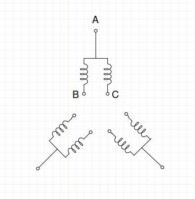
                3 sets of two coils connected internally give 9 wires. With an ohmmeter (low resistance range of multimeter), first identify which groups of 3 wires are connected together. (A, B & C)

                Then identify the centre connection A of each triplet. The resistance between the two coil ends B to C should be greater that of either coil end to the centre, AB and AC.

                dahlander9.jpg

                Write it all down, it's the sort of job I get wrong!

                Once the ABCs are identified, John Rudd's star and delta circuits can both be made.

                Dave

                #500671
                David Davies 8
                Participant
                  @daviddavies8

                  Zan

                  you have readings for 7-8 & 8-9 of 4.1 ohms. You don't show one for 9-7. If this also reads 4.1 ohms this proves that there is a star point buried in the motor windings. (The value of 4.1 ohms is equal to 1.732 x 2.4 ohms).

                  Following your link diagram taken from the motor, the low speed connection is double star, where 4,5 & 6 form the other star point and linking 1-7, 2-8 and 3-9 puts the two star configured winding sets in parallel.

                  If I knew how to attach my sketch I would.

                  HTH

                  Dave

                  #500673
                  David Davies 8
                  Participant
                    @daviddavies8

                    Sketch of double star connection added to photo album.

                    Note: Inserting photos is done using the two buttons just before the Smiley Button top right of the editor tool bar.  The 'Camera' inserts photos from a Forum Album, the other allows a URL to a photo anywhere on the internet.   Only JPG images are allowed.

                    Edited By SillyOldDuffer on 11/10/2020 10:00:09

                    #500713
                    Zan
                    Participant
                      @zan

                      Thanks sod and David. Yes I missed the 9-7 at 4.1 ohm I discovered that at 2 am as there was no way for this to happen in a delta connection and found the 7-9, with repeated meter readings, and thus 78&9 could only be connected as a star, after 4 sheets of attempted drawings being the only possible way it would work . However by that time my head was spinning Too much to post!
                      I was under the impression that any star connection would not work at 240 v however after a lot of trawling with the Dahlander connections (thanks John, the actual name of the connection was a great help) I did find one reference to a star working at 240v but John’s diagram now makes this abundantly clear…

                      it seems that it was connected in the only way it would work and actually there was no problem at all! That’s The trouble with limited understanding, it’s hard to actually pin down to a faulty motor or inverter, and which caused the problem, one ,the other, or both!

                      However it’s very good to be absolutely sure I killed this inverter with the momentary disconnection of the motor while changing direction, although it did take a while to actually fail , the first Inverter was I think just bad luck. So now a decision, a cheap £70-90 inverter off the bay or a decent Modern vector type at £180 plus……

                      I think the latter, as I am contemplating removing the varispeed head because of noise in a home workshop , it’s fine in a massive industrial or educational environment. But I have to use ear defenders all the time when using the machine then the inverter will provide the speed change and I’ll use a multi groove belt .  I enjoy messing about with machines, after building my first lathe as a final year project at teacher training, built a Dore west bury miller, converted a sieg sx2 to cnc and much modified my decker type tool and cutter grinder 

                      thanks to all


                      Edited By Zan on 11/10/2020 10:51:39

                      #500994
                      Martin Bryars
                      Participant
                        @martinbryars38535

                        I have just bought a refurbished Bridgeport with a Varispeed head which is very quiet indeed. There are videos on You Tube showing how to rebuild one. It is certainly much quieter than the Harrison mill I have sold, which was in good condition. I think if I were starting from where you are, I would rebuild the head.

                        I have inverters on both the Bridgeport and my Myford 254. Both are Mitsubishi. The one on the lathe is guaranteed for 10 years by Newton-Tesla, it being bought as part of their conversion package for a Myford to 3 phase. A 10 year guarantee normally implies a long life expectancy.

                      Viewing 10 posts - 1 through 10 (of 10 total)
                      • Please log in to reply to this topic. Registering is free and easy using the links on the menu at the top of this page.

                      Advert

                      Latest Replies

                      Viewing 25 topics - 1 through 25 (of 25 total)
                      Viewing 25 topics - 1 through 25 (of 25 total)

                      View full reply list.

                      Advert

                      Newsletter Sign-up