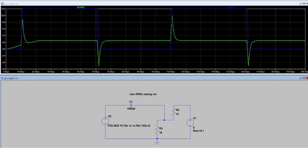
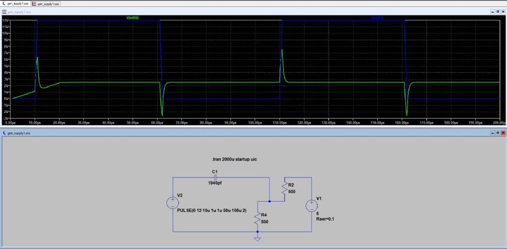
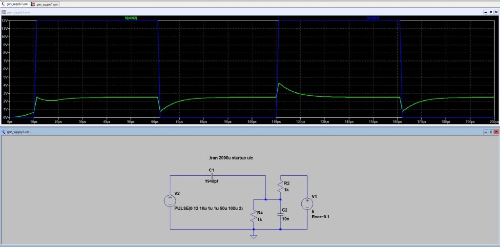
A bit more description of what we've got. The system is 3 aspect colour lights, controlled by Arduino Pro Mini in each signal. The 12v and ground are obvious, the third wire communicates between signals to tell a signal that the following one is on red and so to show yellow. At the driver end it is connected to ground via 1k, at the driven end it is connected to 5v via 1k, so most of the time it is at 2.5v but when it wants to send a message the driver end is grounded by an open collector transistor, actually a ULN2003 and it drops to ~ 0.6v, if the connection is lost, it rises to 5v and so it flashes an error code. I use 'message' to avoid confusion with 'signal', which is the complete box of tricks. Distance between signals is about 50 metres.
The system has been working fine for about 2 years, but we've suddenly had a spate of failures. The first 2 were after the long lock-down (no I'm not blaming coronavirus), and we've had 3 more in quick succession. These last 3 were in one batch of Arduinos. I'm coming to the conclusion that we've been sending too much voltage, because the nominal 12v is actually 13.8 when the battery is well charged, and so I'm fitting external voltage regulators to power the Arduino with 5v, but it would be fairly easy to add zenners/1M resistors/extra capacitors to the message wire.
Joe's post makes me think I should do something, adding zenners/1M resistors/extra capacitor would be possible, changing the circuitry around the Arduino not easy. Do I add zenners or caps, or both? I'm going to repeat Joe's experiment and will report back, in fact I've just remembered we have a 100m drum of cable waiting for the next phase of extension, so I can try it on that in the comfort of my workshop. Just one point on Joe's test, shouldn't there be a capacitor from the nominal 2.5v point to ground?
Thanks for all the replies.
Edited By duncan webster on 11/09/2020 11:36:30
Edited By duncan webster on 11/09/2020 11:42:49
Edited By duncan webster on 11/09/2020 11:59:26
SillyOldDuffer.


