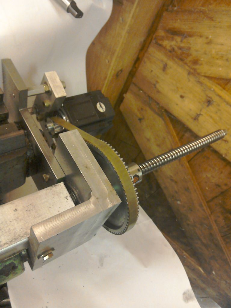
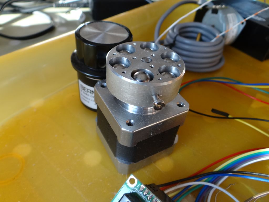
I did quite a bit of work on the 'rattle dampers' – fitted one to each axis of my small CNC router, which upped the rapids hugely Also fitted one to the stepper on my rotary table/hobber, which likewise upped the max rates tremendously. For the life of me I cannot find it in all my posts on this forum! No search mechanism here helps…
Anyway, I don't wish to contaminate this thread with info on all that, but to extract the available torque from a stepper requires that the correct supply voltage be used – as high as possible – to overcome Di/Dt at high(er) rpm's, where torque will fall anyway, but if the supply volts are as high as possible, at least that will not cause premature loss of torque.
Another critical element is stepper acceleration. If accelerated very slowly you would normally not have any issues – and unless really undersized, no steps easily lost. This would be the typical use in an auto-feed say on a mill axis, where acceleration is not normally an issue. It is a different matter on a NC application, where rapid moves are at high(er) speed, so acceleration tuning becomes key.
However, a stepper can also lose steps, and even start to go in reverse(!) when it hits bad mechanical resonance.
Coupling the stepper to the machine shifts the resonance point, but it is still there. Coping with this resonance is achieved in two ways – acceleration through the resonance point(s) as quickly as possible, fitting a flywheel to force the rotor through the resonance without stalling, or fitting a viscous or rattle damper.
There is a lot of info available of the design of a viscous damper, and they work very well – are the best type. However, it is still almost impossible to design one in the hobby shop, as you need to know so many paramaters regarding the machine the stepper is driving – all inertial masses, friction coefficient, damping constants, stiction, etc – nigh on impossible for the hobby man to measure.
My rattle dampers were a fair suck on both thumbs – first I found the resonance point of the system ( stpper mounted on the machine) where the stepper would stall or lose steps. Then I added a plain flywheel and sized that till it no longer occurred. Then search for new resonance point and change the flywheel circumferential mass till that resonance no longer caused a stall – then checked the first resonance point, etc…
When resonance was no longer an issue of concern, I then pushed the stepper acceleration , till it stalled or lost steps, and then drilled out that flywheel and fitted mild steel slugs – rods – as close to the periphery as practical. I found the acceleration achieved was then easily 2 to 3 times more, before problems reappeared.
Unlike the viscous damper, there is NO design info, patent, or published science on the rattle damper..
But is does work very well indeed, even if you have to become a little infantile and suck your thumb.
I have no idea if my 'design' is optimal, or what can be done to make it better, but the concept does seem to be effective over a broad design envelope, and very forgiving of error margins. But do the flywheel versus resonance thing first – the flywheel alone already enabled around a 1.2 to 1.5 times acceleration increase.
High stepper acceleration is not required as all, for powered axis drives, lathe auto-feed drives, mill Z axis raising, etc. I doubt you will need more than a 2NM stepper to lift the bench top mill Z axis, with a good ratio drive between stepp and leadscrew. If you accelerate slowly all will be fine.
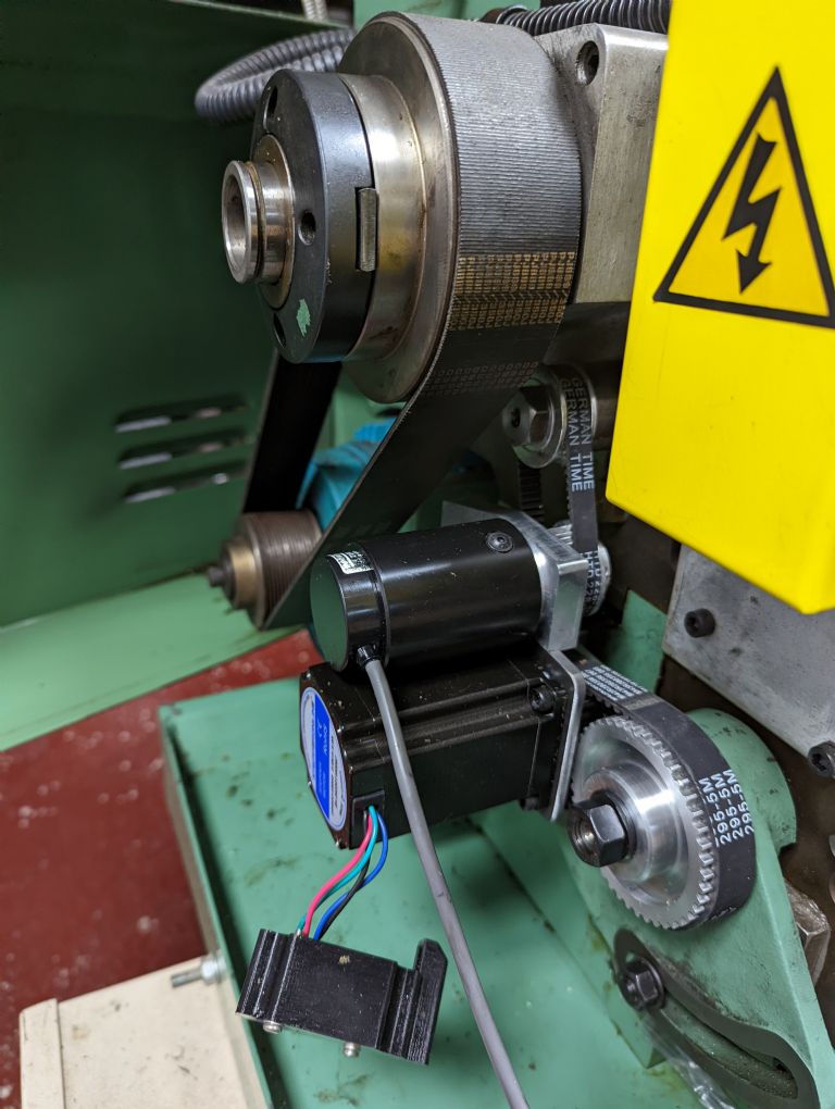
However, electronic threading on the lathe, or gear hobbing is different. When pushing the envelope – high RPM ( 150 to 400) and large thread pitches ( 3mm say) require that the stepper accelerate the leadscrew ( and carriage) very rapidly to ensure the cutting tool and thread being cut are in synch when starting to cut the thread. Lost steps here are a major pain.
And there's the dissertation again. I have a few very detailed posts on these subjects, on the forum – can't find them…penalty for posting to much rubbish.
Joe
Stephen Ward 1.


