Three phase Variac Internal wiring

Advert

Three phase Variac Internal wiring

Home Forums Electronics in the Workshop Three phase Variac Internal wiring

Viewing 15 posts - 1 through 15 (of 15 total)
  • Author
    Posts
  • #32052
    Simon Williams 3
    Participant
      @simonwilliams3

      Renovating a three phase variac

      Advert
      #441707
      Simon Williams 3
      Participant
        @simonwilliams3

        Good morning all, and Seasons Sunday Greetings.

        I have been given a three phase variac, but it's not all it seems.

        Firstly the details:

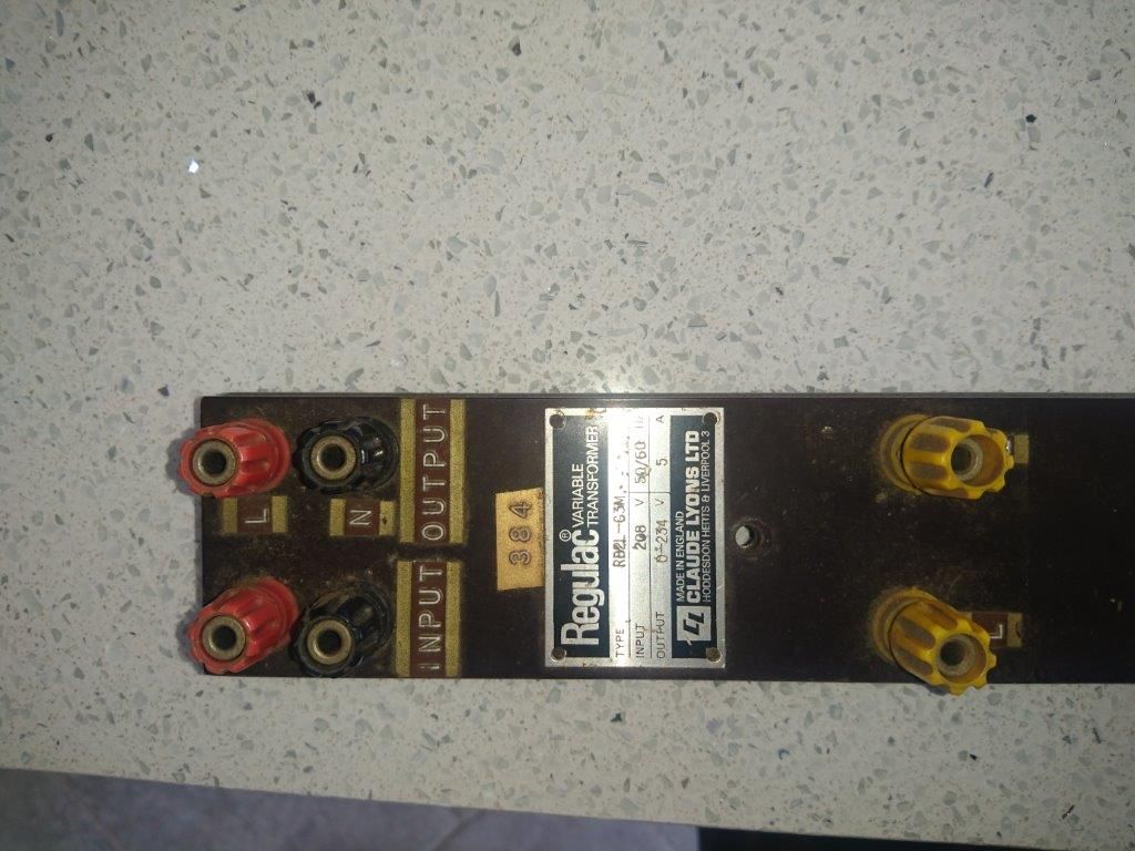
        dsc_2148-1.jpg

        That little identity plate shows it as type no RB2L-G3M

        Input 208 volts 50/60 Hz

        Output 0 – 234 V 5A

        When I stripped the covers off to discover if it was safe to energise, I found the wiring to the input and output terminals had been cut. I've freed up the mechanism and cleaned it and now have energised it but have run into a problem with the applied voltage.

        If I apply 50 Hz volts at 115 volts to one of the three sections of the transformer across the windings. the static no load current is about 130 mA. I can vary the output voltage with the position of the slider all exactly as I would expect a Variac to behave.

        If I increase the input voltage to 210 volts the static no load current hikes up to over 6 amps, and the magic smoke appears as the windings overheat. Turn it off and have a rethink!

        If that input voltage figure is to be interpreted as 208 volts line to line connected in delta that would correspond to 120 volts line to neutral in star., which gets me into the envelope where the thing seems to be happy. Is that what the nameplate means?

        I assume what is happening with my 210 volts applied directly across one of the transformers (ie star connected) is that the core is going into saturation, and thus the inductance of the transformer plummets and the current isn't controlled by the self inductance of the winding. Anyone got any better ideas?

        Thanks as always in anticipation

        Best rgds Simon

        x

        #441713
        Bill Davies 2
        Participant
          @billdavies2

          Hi Simon.

          Is it a three phase variac? It seems odd that only one line is labelled as input. I have repaired equipment with 1-ph variable transformers, and the line/live inputs and outputs are separate. Is it an auto transformer, which shares the winding for input and output, rather than having electrically separate windings?

          Bill

          #441714
          Les Jones 1
          Participant
            @lesjones1

            I agree with Bill that it does not look like a three phase variac. It does not even look like single phase variac.(Although the information on the label would match a single phase variac.) Can you post a picture of the inside of the item. If you are familiar with single phase variacs then a three phase one just looks like three single phase ones mechanically linked together.

            Les.

            #441716
            Simon Williams 3
            Participant
              @simonwilliams3

              Hi Bill, I didn't explain enough – I have three variacs stacked on a common frame, with the rotors connected mechanically to a single knob. I'll post another picture of the whole assembly later.

              The terminal board (with extra extensive safety features!!!!!!!!) has a single input neutral, and three coloured line input terminals coloured red yellow and blue. Adjacent are mounted output terminals also coloured red yellow and blue, with a single black neutral that I would assume is connected to the input neutral as the whole thing is only ever an auto-transformer.

              The photo above shows the top half of the terminal board with the red and yellow input and output terminals, also the black neutrals. Again, I'll put some more photo's up later.

              So it's a three phase variac if I connect it to three phases – which I don't have! I had some idea to split the assembly 'and end up with three single phase variacs, but that won't fly because of the issue over the input voltage.

              #441727
              john swift 1
              Participant
                @johnswift1

                Going by your photo it looks like it the 208 V input had been wired a fixed 89% tap and common input / output

                to give you a stepped up output of 234V 1.125% out across the total winding


                For single phase use

                I would rewire the transformer to connect your single phase supply to the ends of the winding

                with the output taken between the common and the wiper (variable tap)

                you will have 0 to 100% of your mains supply available


                variac.jpg

                John


                add diagram

                Edited By john swift 1 on 15/12/2019 14:11:58

                #441738
                Simon Williams 3
                Participant
                  @simonwilliams3

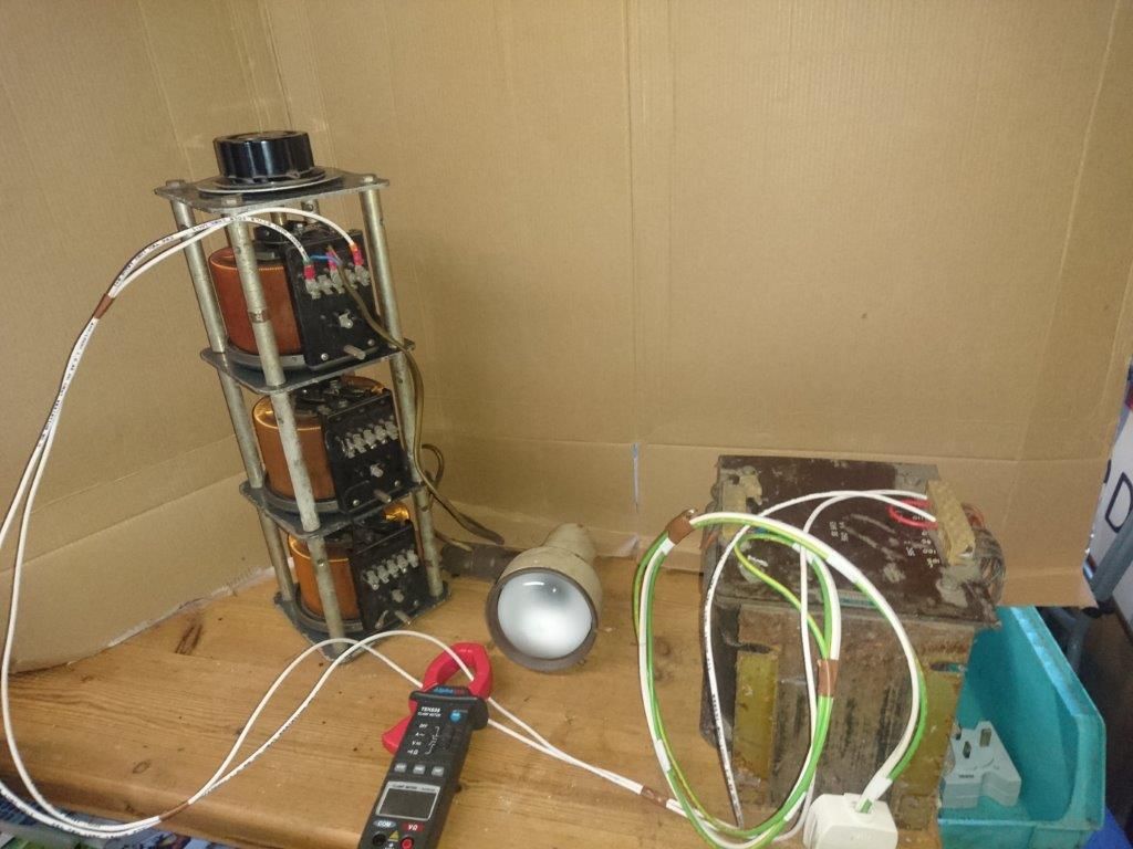
                  Good afternoon, and thanks for the help so far. Firstly a picture of the whole gismo, just to show it is a three phase unit.

                  dsc_2149-1.jpg

                  The transformer right of picture is my "source" – it has a selection of secondary windings which means I can vary (to some extent) the input voltage to the variac under test. The scratty looking desk lamp is just a suitable load, and was diconnected when I was doing the "no load" current draw tests.

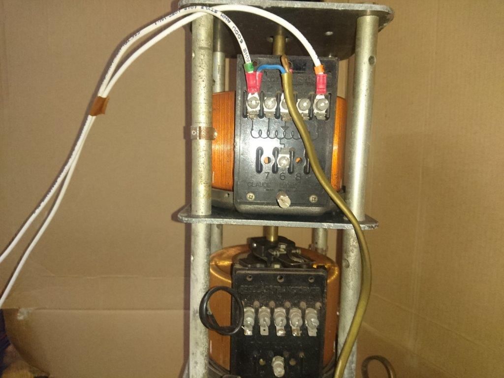
                  Here is a picture of the terminal arrangement for each of the variac elements:

                  dsc_2150-1.jpg

                  If you look closely at the solder remnant on the tags, you can see that the original wiring was connected to a tap on the winding, not the top end. Just as John says I thought if I connected to the end of the winding I could apply anything up to 234 volts and bob's yer mother's brother. Not so.

                  Here's another close up of the terminals for each stage – this time of the middle section so my test wiring isn't obscuring the legend.

                  dsc_2151-1.jpg

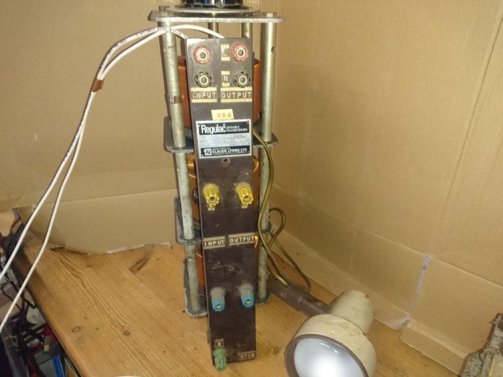
                  And lastly a better picture of the user interface terminals propped against the chassis –

                  dsc_2152-1.jpg

                  #441754
                  Robert Atkinson 2
                  Participant
                    @robertatkinson2

                    Hi

                    This Variac was wired for 208V line to line (Star). Each section sees 1/root 3 (1/1.73 =0.578) of 208V = 120V.

                    So you have 3 x 120V variacs.

                    Robert G8RPI

                    Edited By Robert Atkinson 2 on 15/12/2019 16:27:29

                    #441755
                    Robert Atkinson 2
                    Participant
                      @robertatkinson2

                      If you can bring it to Cambridge (UK) I'd happily swap it for a 240V unit

                      Robert G8RPI.

                      #441780
                      john swift 1
                      Participant
                        @johnswift1

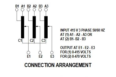
                        Looking at the photos in post 3

                        it looks like you have something like the 3 phase variac from RS components

                        RS stock number 890-2856

                        rs components 3 phase variac.jpg


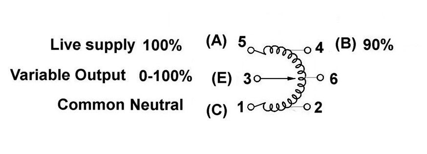
                        your variac terminals look like this

                        variac b.jpg

                        the letters A to E match the RS Components diagram

                        the neutral, if used , going to the star point C1+C2+C3

                        if you connected your lamp between 1 & 3 (C & E) and it did not work

                        check the winding continuity between 1 & 5 (A & C) and the carbon brush is OK and making contact with the winding


                        John


                        Edited By john swift 1 on 15/12/2019 18:37:34

                        #441782
                        Simon Williams 3
                        Participant
                          @simonwilliams3

                          Robert – thank you – I think you have confirmed the answer I'd thought. I'm more than slightly bemused how such an item came to be in this country, though the chap who gave it to me did work for a while in Canada. Why would he have brought this great lump home – we may never know. Unfortunately he's asked me to loan it back to him to run some antique 120 volts (American) Christmas lights – I've got to go and see him on Wednesday and break the news that this ain't going to work.

                          As for the suggestion of a swapsie, that might not be as far fetched as it sounds as I have family in Peterborough. I'll send you a PM and we'll see if we can work something out.

                          John – my test set up with a filament lamp works perfectly – provided I only put 120 volts on the input terminals. My input voltage comes from the big transformer, the tappings on this are such that I can only try 100, 120 0r 210 volts or stick the mains on it directly. With 120 volts on the input terminals of one section as a single phase auto=transformer I can twiddle the dial and alter the dimness of the lamp completely as one would expect.

                          I was curious to see if my theory about the saturation of the core leading to loss of control of the self inductance and thus input current met with any approval within the community. I tried it at first on 230 volts input but realised the current was ridiculous, so I'd imagined I'd got a shorted turn. But then I tried it on 120 volts and the current was sensible that scotched that theory. Besides,. all three sections behave the same.

                          So many thanks for your help, and season's greetings to all.

                          Simon

                          #441786
                          Robert Atkinson 2
                          Participant
                            @robertatkinson2

                            Hi,

                            Yes it will saturte at around 180V. To get 0-120 volts connect two sections in series and use the output from one. No connection to the "upper" wiper.

                            Robert G8RPI.

                            #441787
                            Simon Williams 3
                            Participant
                              @simonwilliams3

                              Ah hah, cunning!

                              How did you calculate the saturation voltage?

                              Rgds Simon

                              #441788
                              John Olsen
                              Participant
                                @johnolsen79199

                                Robert, I don't think that connection with the two in series will work properly, at least not if you put any load on it. The impedence of the one with the load on will be lower than the other, so the voltage will vary with the load. The two cores would need to be magnetically coupled for it to work well.

                                We once had a number of VHF receivers that were burning out lots of mains transformers, a little 25 VA affair. By testing (with a Variac!) we found that they had too few turns on the primary, and were only good for about 180V input. The magnetising current below that was very small, only 20mA or so, but there is is very pronounced knee in the curve when you reach saturation. We successfully rewound one with about 20% more turns and that gave no further trouble, but of course that was an unauthorised modification and we could not persuade the powers that be to let us fix the rest, so we just had to keep on changing the transformers at frequent intervals.

                                John

                                #441794
                                Robert Atkinson 2
                                Participant
                                  @robertatkinson2

                                  Hi,

                                  Saturation voltage is an educated guess from experience.

                                  The circuit shown will work fine up to full current (5A in this case) on one variac. Think of 2/3 of a 3 phase star connection run unbalanced.

                                  I just looked to see if I could find justification ofr my statement and found this  "CONNECTION — SINGLE PHASE SERIES: By jumperingthe common connections, two equal single units (or two equalgroups of paralleled units) driven by the same shaft may beused at double voltage (line-to-line) in single phase serieswith external connection only to the input and output termi-nals. The load must be grounded. If an input neutral is con-nected to the common, an output neutral may be used.Transformer or loads need not be balanced to neutral "

                                  at  https://variac.com/staco/PDFCutSheets/VT%20designengine.pdf

                                  Robert G8RPI.

                                  Edited By Robert Atkinson 2 on 15/12/2019 20:41:59

                                Viewing 15 posts - 1 through 15 (of 15 total)
                                • Please log in to reply to this topic. Registering is free and easy using the links on the menu at the top of this page.

                                Advert

                                Latest Replies

                                Viewing 25 topics - 1 through 25 (of 25 total)
                                Viewing 25 topics - 1 through 25 (of 25 total)

                                View full reply list.

                                Advert

                                Newsletter Sign-up