Arduino DRO

Advert

Arduino DRO

Home Forums Electronics in the Workshop Arduino DRO

Viewing 12 posts - 1 through 12 (of 12 total)
  • Author
    Posts
  • #382741
    Peter Bell
    Participant
      @peterbell11509

      I have had success with a dro based on a rotary encoder fitted to the lead screw of my mill described on the site below.

      Home Brew DRO – WDMES – Warrington & District Model Engineering Society

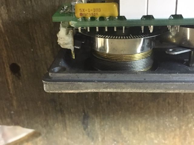
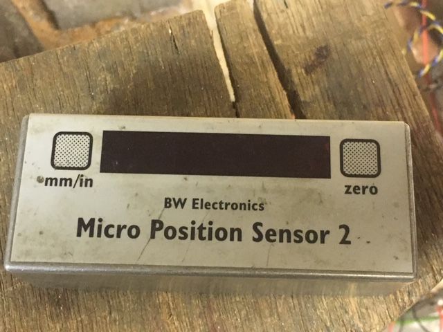
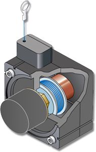
      I have another DRO application but this time I would like to make a draw wire spring return linear encoder but using a rotary encoder in the style of one in the pics from BW Electronics which works well.

      I know there are commercial units units available at suitable prices but before attempting I wondered if anyone had constructed one using an optical (ebay around £8.00) or magnetic rotary encoder?

      Peter

      img_3154.jpg

      img_3155.jpg

      plinie_posiwire_4.jpg

      Advert
      #31989
      Peter Bell
      Participant
        @peterbell11509
        #382788
        Bob Mc
        Participant
          @bobmc91481

          Hi Peter…

          I have been thinking about making a wire draw DRO for the y axis on my lathe, as you say commercial units are available but are rather expensive… the rotary encoders on ebay would be suitable if a wire draw mechanism was available with it .

          Using the Arduino for the control and readout is the easy part..and after much deliberation as to how to fit some sort of wire draw retractable mechanism it occurred to me that something like a tape measure or retractable dog lead might be the answer but they are not exactly what is required.

          I came across a possible solution when I saw for sale a retractable key ring, this is fairly small and has a reasonably good retracting pull, the torque needed for the rotary encoder is very light and the only consideration would be to fit the mechanism to the encoder and to the machine…and it is very cheap.

          I haven't got round to doing the job yet…but pictures below show the parts; for my lathe I only need a readout for the cross slide I have bought a normal dro from Chester Machine tools for this which sits in line with the bed and is just where the line of sight with the work is…. anyway see pics below…hope this might be of use…

          rgds…Bob…

          The x axis readout below.

          dsc_0075.jpg

          Rotary encoder.

          rotary encoder.jpg

          Retractable keyring .

          retractable keyring.jpg

          #382807
          duncan webster 1
          Participant
            @duncanwebster1

            I'm glad you got the Arduino DRO to work. If I did the software again I might do it differently to avoid using floating point arithmetic, which would make it work faster I think. Not that speed has ever been an issue with mine, no matter how fast I twiddle the handle it always comes back to zero when I return to base.

            If the ebay encoder is **LINK**

            the description is a bit Delphic. If 400 P/R means pulses per rev it might mean a 200 slot wheel, 800 edges per rev. To get 0.001" resolution you would need a drum circumference of 0.8", 0.254" diameter which is unfeasibly low. The original design on my lathe has a 90 slot wheel, 360 edges on a 1mm pitch leadscrew. You could gear it up but you'd then have to think about backlash in the gears.

            Since building the original I've discovered LED displays which are much more readable than LCD. The software could be modified to suit fairly easily.


            Edited By duncan webster on 28/11/2018 22:09:29

            #382838
            Peter Bell
            Participant
              @peterbell11509

              Hi Bob & Duncan,

              Thanks for the helpful replies and Duncan with your work in getting the original DRO up and running for all to use. I’m not very experienced with Arduino but working on it! The LCD displays are good but I was wondering if a 7 segment display with be better and less critical of the viewing angle. Got a Max7219 8 digit 7 segment module on order to play with.

              I had thought of a retractable key ring but realised that I have a few scrap 3m tapes. Dismantled, this revealed a 0.12 thick, 9mm wide return spring easily long enough to try. This I was going to put in a spring barrel at one end. Have two plates with the wire drum in the middle and the encoder at the other end on a ball bearing spindle if you see what I mean.

              Yes that was the encoder I was going to use. It hasn’t arrived yet but I also found this magnetic type which gives a genuine 256 ppr. Could do with a higher count but want to avoid gearing. The wire drum dia is something unknown at present but the BW Electronics version looks to be fairly coarse on the encoder and uses a drum about 0.8” dia. Any guidance on drum dia will be gratefully received!

              Peter

              https://uk.rs-online.com/web/p/rotary-encoders/7140237/

              #382861
              IanT
              Participant
                @iant

                Hallo Peter,

                Been in the process of mounting a 4" (moveable) DRO to the X-axis of my smaller mill but I like the idea of the wire encoder. So please keep your postings going.

                As I've mentioned here before – I prefer the Micromite to the Arduino – which I can interactively develop with and which supports a wide range of displays (including touch) 'out-of-the-box'. As an side, last night I was looking at Grbl1.1f (as a friend is trying to use it with an Arduino Nano on a laser printer) and having multiple compiler errors. I'm afraid I've been spoiled by using (to me) the much friendlier MM environment. So if I do this, I will walk my own path in that respect – but the encoder itself is certainly interesting.

                I've got some key-ring pulls but would have thought that they might not be strong enough in this application.

                Please keep us posted.

                Regards,

                IanT

                #382909
                duncan webster 1
                Participant
                  @duncanwebster1

                  If you want 1 thou resolution then an edge has to pass one of the sensors every thou (obvious). This means that (wheel circumference)/edges = 1/1000. You actually have to allow for wire diameter as its the wire pitch diameter that matters, but we can do that later. With a 1" wheel you have a circumference of 3.1416" so you need 3141.6 edges. Clearly you can't have that so settle for 3200 (it has to be divisible by 4) and increase the wheel diameter to suit (1.0186&quot, then take off the wire diameter. 3200 edges is 800 slots, it isn't clear to me how many slots your encoder has.

                  If you want metric with a resolution of 0.02mm then you need twice as many slots and a slightly different wheel diameter, I'll let you work it out

                  What you can do is wire the new encoder in place of your existing one on your milling machine. Zero the display then turn the spindle one rev and note the reading. You can then work out how many slots are in the encoder as you know how many the current one has.

                  I think this leads me to the think I wouldn't start from here, pull wire sensors and high resolution is difficult.

                  #382928
                  John Baron
                  Participant
                    @johnbaron31275

                    Hi Guys,

                    FWIW every HP inkjet printer has an linear optical positioning system that is easy to get at and provides directional information. The reader head, whilst different in size to say a slot opto, is very similar electrically. Without checking the technical data sheet for the optical reader head I don't know how fine the steps are, certainly the tape is at least 200 lines to the inch.

                    #382932
                    Les Jones 1
                    Participant
                      @lesjones1

                      Just a warning about rotary encoders removed from HP printers, One of my first attempts at putting a DRO on my mill I tried using an encoder from an HP500c printer. If irst did some tests turning it by hand one revolution. I got 500 counts. When fitted I found it was not quite right. It turned out it was 504 counts per revolution. So don't assume it will be a nice round number.

                      Les.

                      #382971
                      Peter Bell
                      Participant
                        @peterbell11509

                        Id previously came across someone else who had problems with low resolution printer tape while trying to use it for a linear scale so left that one alone. I also recently came across an ic which read magnetic tape but decided that would need a quite a lot of development to make it into a working linear encoder?

                        The common ebay Chinese rotary encoders appear quite well made and seem to come in a few different specs with pulse per revs ranging from 360, 400 and 600 with a great lack of manufactures info in the traditional manner. However some listing have snippets of info, like

                        Pulses: 600 p/r (Single-phase 600 pulses /R,Two phase 4 frequency doubling to 2400 pulses)

                        Output :AB 2phase output rectangular orthogonal pulse circuit, the output for the NPN open collector output type

                        So it looks like a 600ppr one is capable of 2400 pulses/rev quad? Assuming that, from a quick stab at a calc I make the drum dia around 0.75” to give 1 thou resolution with 0.5mm stainless wire? I’m sure someone will correct me but it seems a starting point to try when the encoder arrives and I can rig something up to try it on the mill with the leadscrew sensor as a standard as suggested.

                        Also the outputs appear to use open collector npn transistors which need a load resistor (1k etc to +5v) to give out the correct waveform?

                        Agree a draw wire sensor not ideal but its not terribly expensive to give it a bash and I used the BW electronics one successfully for years.

                        Peter

                        #383000
                        duncan webster 1
                        Participant
                          @duncanwebster1

                          If P/R means slots then you are in with a chance as you would have 1600 edges. You can set the Arduino inputs (on 2 & 3) to be INPUT_PULLUP which adds a pullup resistor for you.

                          #383130
                          Michael Gilligan
                          Participant
                            @michaelgilligan61133

                            Peter,

                            I have sent you a personal message

                            MichaelG.

                          Viewing 12 posts - 1 through 12 (of 12 total)
                          • Please log in to reply to this topic. Registering is free and easy using the links on the menu at the top of this page.

                          Advert

                          Latest Replies

                          Viewing 25 topics - 1 through 25 (of 25 total)
                          Viewing 25 topics - 1 through 25 (of 25 total)

                          View full reply list.

                          Advert

                          Newsletter Sign-up