Prototype Boards

Advert

Prototype Boards

Home Forums Electronics in the Workshop Prototype Boards

Viewing 25 posts - 1 through 25 (of 53 total)
  • Author
    Posts
  • #374269
    Peter Bell
    Participant
      @peterbell11509

      Using a standard prototype board( newish departure from a rats nest for me) for some Arduino work and struggling to attach an I2C display without it rolling about, also finding any toggle switches to plug straight in?

      Can anyone offer any advice or advise what suits them?

      Thanks Peter

      Advert
      #31976
      Peter Bell
      Participant
        @peterbell11509
        #374281
        Mike Poole
        Participant
          @mikepoole82104

          Have a look at PCB slide switches and push buttons, they will often plug into the board.

          Mike

          #374287
          I.M. OUTAHERE
          Participant
            @i-m-outahere

            You can get toggle ,slide , push button and tactile switches in pcb mount . Easiest way to find what you want us search eBay , I can’t recommend a store to buy them as I don’t know where you are . Not sure what you mean with the display – what type of display ? Lcd , led , Tft ? For testing I usually screw everything to a piece of mdf using standoffs and small sheet metal screws . I also have a piece of aluminium angle that has some holes drilled in it to facilitate a few different types of panel mount switches and this angle also gets mounted to the mdf board.

            #374289
            SillyOldDuffer
            Moderator
              @sillyoldduffer

              Try adding 'breadboard friendly' when searching ebay/amazon etc for parts.

              I don't normally bother fixing stuff down when breadboarding but occassionally use a thin ali panel much like XD351 and his angle for switches and pots, and plasticene or insulating tape for temporarly holding displays in position. Some modelling clays are more suitable than others. It has to be a bit sticky without being too soft or messy.

              Dave

              #374315
              Peter Bell
              Participant
                @peterbell11509

                Thanks for the replies and ideas.

                A search using "breadboard friendly" has brought good results and switches which will do. The display is only a 2 line lcd but just realised that the board has an adhesive back so I can fabricate a bracket and attach it to take a display or switches.

                Talking of displays is there a recommendation for an easy to use reasonably sized Tft?

                Peter

                #374317
                John Rudd
                Participant
                  @johnrudd16576

                  Many folk have used the Nokia 5110 display in their projects or is that too small?

                  #374318
                  John Rudd
                  Participant
                    @johnrudd16576

                    Many folk have used the Nokia 5110 display in their projects or is that too small?

                    Plenty on ebay

                    #374319
                    Peter Bell
                    Participant
                      @peterbell11509

                      Yes I'd like something a bit bigger if possible?

                      #374321
                      John Rudd
                      Participant
                        @johnrudd16576

                        Other sizes on ebay…..

                        #374322
                        SillyOldDuffer
                        Moderator
                          @sillyoldduffer

                          My current project uses a Sainsmart TFT Shield with a 3½ screen, which plugs into a Mega. (Although the link is to the US, I got mine in the UK, probably via Amazon.) Display and touch both work ok with the TFT library.

                          The main problem with TFT screens is the large number of connections needed. Lots of wires, and not many Input Output pins left for other work. I find a Mega provides much more room to maneuver than the Uno – more pins.

                          The shield considerably simplifies and tidies up the wiring! It also comes with an SD-Card interface, which may be handy.

                          Getting at the unused pins on the Mega under the shield is slightly awkward but right angled connectors fit OK. The main downside is the cost, but it's a neat solution.

                          Dave

                          #374337
                          Peter Bell
                          Participant
                            @peterbell11509

                            Thats impressive! Didnt realize the amount of pins that's needed, rather assuming that I2c would take care of things like that, bit too advanced for my present state of development!

                            Must admit find the cheap1602 type lcd display with white letters very readable but want to progress/learn as you do hence the question.

                            Thanks Peter

                            #374353
                            Bazyle
                            Participant
                              @bazyle

                              I have been looking at the other direction – not wanting to work through lots of menus to put in data I thought of BCD switches. While the pcb mount ones are common anything larger is frighteningly expensive. So going with switches and binary input until I can make my own rotary BCD.

                              #374379
                              SillyOldDuffer
                              Moderator
                                @sillyoldduffer
                                Posted by Peter Bell on 03/10/2018 11:01:26:

                                Thats impressive! Didnt realize the amount of pins that's needed, rather assuming that I2c would take care of things like that, bit too advanced for my present state of development!

                                Thanks Peter

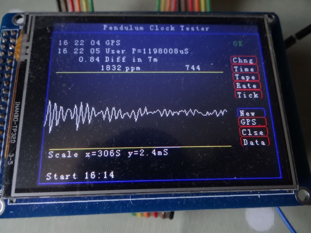
                                You can deliver a powerful user interface with a Touch Screen TFT so they're well worth investigating. My clock analyser looks like this:

                                dsc05282.jpg

                                The screen does 320×240 colour pixel graphics and there's a fairly simple library for writing to the screen and detecting X Y coordinates when a pen touches it. I wrote a small class library to do buttons, and – because displaying text is amazing slow on a TFT – a class that only updates text objects on change. Not much more difficult to do basic things than a 1302 LCD but knowing C++ helps if you want buttons. (I haven't found a standard library that provides GUI controls.)

                                I'm not aware of an I2C or other serial interface being available for these screens: I guess serial is too slow. Speed problems sometimes cause bother with 1302 LCD displays as well. These are fastest in 8 bit mode, reasonable in 4 bit, and slowest with I2C. Worth checking the display is quick enough if your project is time critical, especially when planning to use I2C. (When not speed critical, I2C is wonderful.)

                                Dave

                                #375281
                                Phil Grant
                                Participant
                                  @philgrant54580

                                  If you're OK programming then have a look at the nextion displays from Itead, they use a serial connection to the Arduino or Pi etc.

                                  They have a PC design tool that allows you to create all the GUI and upload it to the display then control it using an Arduino, I found it quite easy to use when I got my head around it and there's quite a bit of information on the web.

                                  **LINK**

                                  #375342
                                  Peter Bell
                                  Participant
                                    @peterbell11509

                                    Thanks looks interesting from the link. Found somes neat toggle and tactile switches thanks to the help from this thread.

                                    I’m only learning I’m afraid but find some of the Arduino error messages a bit misleading also the syntax confusing. Some success with simple things like counting and i2c displays but AttachInterrupt doesn’t want to play ball at present.

                                    #375346
                                    Phil Grant
                                    Participant
                                      @philgrant54580

                                      Did you realise the attached interrupt only works on certain pins?

                                      #375352
                                      Peter Bell
                                      Participant
                                        @peterbell11509

                                        Yes, I’m using a Nano which has only two pins and got the correct pin no’s.

                                        all I want to do is inc a variable from a string of pulses from a proximity sensor, and count them. Got display and outputs working ok. It was suggested I use an attached interuppt with a service routine, perhaps there’s a better way?

                                        #375365
                                        SillyOldDuffer
                                        Moderator
                                          @sillyoldduffer
                                          Posted by Peter Bell on 10/10/2018 15:25:39:

                                          all I want to do is inc a variable from a string of pulses from a proximity sensor, and count them. Got display and outputs working ok. It was suggested I use an attached interuppt with a service routine, perhaps there’s a better way?

                                          Two ways to count pulses:

                                          • spin digitalRead() in a loop until a pulse is detected, then count it. Advantage is simplicity. Huge disadvantage is that nothing else can be done while the Arduino is waiting for the next pulse. As an approach it's only suitable for trivial processing.
                                          • Set up an interrupt and call an ISR. This allows the arrival of a pulse at any time to suspend whatever the Arduino is doing, execute the ISR, and then resume from the break. Advantage is the microcontroller can appear to be doing several things at once. Disadvantage is interrupts are bit more complicated to understand, mainly because of the time element.

                                          Two common problems:

                                          • Any variable shared between an ISR and the rest of the world must be in scope of both functions and declared 'volatile'. Scope can be fixed by declaring shared variables at the top of the source code (before any functions) making them global. The 'volatile' keyword tells the compiler that it must not cache the declared variable to optimise performance. If a global is cached, it's entirely possible for it's value at point of use to be wrong because the ISR updated the master leaving other functions with out-of-date copies. Then the program doesn't work as expected.
                                          • Because an ISR interrupts other functions that can themselves be time critical, the ISR should be short and quick. If an ISR is long-winded and the code it interrupted times-out, then chaos can ensue.

                                          Both issues produce hard to diagnose bugs. You can have code that's logically correct and be getting random errors or a complete breakdown depending on the state of a buffer and/or how long something takes.  Very confusing.

                                          Happy to look at your code Peter if that helps.

                                          Dave


                                          Edited By SillyOldDuffer on 10/10/2018 16:43:23

                                          #375366
                                          Phil Grant
                                          Participant
                                            @philgrant54580

                                            I do have experience with Arduino coding so if you want to post your code I will have a look at it I have used interrupt routines in the past and remember it was a bit of a pain to get working.

                                            #375379
                                            Peter Bell
                                            Participant
                                              @peterbell11509

                                              Thanks for the offers of help. Presume just copy the code in somehow?

                                              I’ll try later if we survive the journey from a very enjoyable day at Kew Gardens

                                              Peter

                                              #375397
                                              Phil Grant
                                              Participant
                                                @philgrant54580

                                                I've had a look at some old code that I used that used interrupts and as I can see you setup the interrupts in the setup part of the code

                                                attachInterrupt(0, Start, FALLING);
                                                attachInterrupt(1, Stop, FALLING);

                                                0 = pin 2, 1 = pin 3, "start" and "stop" are the names of the functions that get called when the interrupts are triggered and the falling indicates that the level goes from high to low to trigger the interrupt.

                                                #375409
                                                Peter Bell
                                                Participant
                                                  @peterbell11509

                                                  Thanks for the replies, very helpful.

                                                  This is part of the code that I want count with from the sensor. It will eventually have more zones and successfully looped using the small delay when I tried it on my breadboard.

                                                  It is my first attempt with Arduino and although I'm sure it could be improved no end I was pleased to get it running with some help from a friend.

                                                  Due to bringing the wrong memory stick with me I do not have the version where I tried incrementing using attached interrupt, sorry.

                                                  I did think that perhaps I should practice adding attached interrupt to blink as pratice when I return?

                                                  #include <Wire.h> // Comes with Arduino IDE
                                                  #include <LiquidCrystal_I2C.h>
                                                  LiquidCrystal_I2C lcd(0x27, 2, 1, 0, 4, 5, 6, 7, 3, POSITIVE); // Set the LCD I2C address

                                                  //int ledPin = 13;
                                                  int ledPin = 2;
                                                  int switch1 = 3;
                                                  int count;

                                                  void setup()
                                                  {
                                                  Serial.begin(9600); // Used to type in characters
                                                  lcd.begin(16, 2);// set up the LCD's number of columns and rows:
                                                  lcd.setCursor(2, 0); // Print a message to the LCD.
                                                  lcd.print("Rail Squirt&quot;
                                                  delay (2000);
                                                  lcd.setCursor(0,1);
                                                  lcd.print(" by Peter Bell&quot;
                                                  delay (2000);
                                                  lcd. clear();
                                                  lcd.print(" Version 2.7M&quot; //Version
                                                  lcd.setCursor(2, 1);
                                                  lcd.print(" 10-10-18&quot;
                                                  pinMode(ledPin, OUTPUT);
                                                  delay (4000);
                                                  lcd. clear();
                                                  delay(1000);
                                                  }
                                                  void loop()
                                                  {

                                                  Serial.begin(9600);
                                                  Serial.println(count);

                                                  lcd.setCursor(2, 0);
                                                  lcd.print("Zone&quot; // ZONE 1 OFF
                                                  lcd.setCursor(9, 0);
                                                  lcd.print("1 OFF&quot;

                                                  if (count > 155 && count < 175) {
                                                  digitalWrite(ledPin, HIGH);// output on

                                                  lcd. clear();
                                                  lcd.setCursor(2, 0);
                                                  lcd.print("Zone&quot; // ZONE 1 ON
                                                  lcd.setCursor(9, 0);
                                                  lcd.print("1 ON&quot;
                                                  }
                                                  lcd.setCursor(9, 0);
                                                  lcd.print("8 ON&quot;

                                                  if (count > 175 && count < 1500) {
                                                  digitalWrite(ledPin, LOW); //output off
                                                  lcd. clear();
                                                  lcd.setCursor(2, 0);
                                                  lcd.print("Zone&quot; // ZONE 8 OFF
                                                  lcd.setCursor(9, 0);
                                                  lcd.print(" END&quot;

                                                  }

                                                  count ++ ;
                                                  lcd.setCursor(6,1);
                                                  lcd.print(count);
                                                  delay(200);

                                                  if (count == 1500) count = 0; //re-sets
                                                  lcd. clear();
                                                  }

                                                  #375411
                                                  duncan webster 1
                                                  Participant
                                                    @duncanwebster1
                                                    Posted by Phil Grant on 10/10/2018 20:46:49:

                                                    I've had a look at some old code that I used that used interrupts and as I can see you setup the interrupts in the setup part of the code

                                                    attachInterrupt(0, Start, FALLING);
                                                    attachInterrupt(1, Stop, FALLING);

                                                    0 = pin 2, 1 = pin 3, "start" and "stop" are the names of the functions that get called when the interrupts are triggered and the falling indicates that the level goes from high to low to trigger the interrupt.

                                                    I think to comply with preferred method this should be

                                                    attachInterrupt(digitalPinToInterrupt(2), Start, FALLING);

                                                    attachInterrupt(digitalPinToInterrupt(3), Stop, FALLING);

                                                    #375412
                                                    Phil Grant
                                                    Participant
                                                      @philgrant54580
                                                      Posted by duncan webster on 10/10/2018 23:01:44:

                                                      Posted by Phil Grant on 10/10/2018 20:46:49:

                                                      I've had a look at some old code that I used that used interrupts and as I can see you setup the interrupts in the setup part of the code

                                                      attachInterrupt(0, Start, FALLING);
                                                      attachInterrupt(1, Stop, FALLING);

                                                      0 = pin 2, 1 = pin 3, "start" and "stop" are the names of the functions that get called when the interrupts are triggered and the falling indicates that the level goes from high to low to trigger the interrupt.

                                                      I think to comply with preferred method this should be

                                                      attachInterrupt(digitalPinToInterrupt(2), Start, FALLING);

                                                      attachInterrupt(digitalPinToInterrupt(3), Stop, FALLING);

                                                      Yes you are right, but on a nano it compiles and works fine using int.0 and int.1.

                                                    Viewing 25 posts - 1 through 25 (of 53 total)
                                                    • Please log in to reply to this topic. Registering is free and easy using the links on the menu at the top of this page.

                                                    Advert

                                                    Latest Replies

                                                    Viewing 25 topics - 1 through 25 (of 25 total)
                                                    Viewing 25 topics - 1 through 25 (of 25 total)

                                                    View full reply list.

                                                    Advert

                                                    Newsletter Sign-up