Electronics assistance – reduction of output DC voltage

Advert

Electronics assistance – reduction of output DC voltage

Home Forums Electronics in the Workshop Electronics assistance – reduction of output DC voltage

Viewing 25 posts - 1 through 25 (of 30 total)
  • Author
    Posts
  • #31952
    choochoo_baloo
    Participant
      @choochoo_baloo
      Advert
      #358994
      choochoo_baloo
      Participant
        @choochoo_baloo

        I am trying to build a resistance soldering unit (RSU) for etched brass kits. I've managed to piece together all of the components, now whilst testing my electrical source, I've had an unexpected result… clearly my understanding is lacking!!

        The RSU requires max 3V DC (adjustable depending on size of piece) with a draw of order 10A.

        1. So I thought I can use my dcent DC bench top power supply (rated to 25A). However it's voltage adjustment is 8.0-13.8 V.
        2. So I then fitted an inline light dimmer on the mains input to the power supply BUT the output DC voltage is the same as before?! I can only think modern power supplies have some voltage regulation that maintains their stated output voltage range?
        3. Now I understand modern dimmers only function with AC, therefore my only option is to fit a variabe resistor at the power supply output, taking the wiper pin to the carbon electrode of the solderer –> I'm struggling to find variable resistors rated at ~ 30W

        Please can someone make suggestions. This is should be a simple task!

        Thanks in advance.

        #358995
        Bill Davies 2
        Participant
          @billdavies2

          Not the most efficient way, dump some of the heat in a rheostat:

          **LINK**

          Cheaper would be a string of powers such as:

          **LINK**

          I don't think your large power supply will like chopped AC going into it, whether an old-school transformer type (is it heavy?) or a modern switched-mode type. The latter type will also regulate itself so the reduced input voltage won't result in a lower voltage output.

          Do you know what current is actually being drawn in trying to make your resistance weld? Would it be possible to control the duration of the pulse of electricity to control the amount of energy delivered?

          Bill

          #358996
          Bill Davies 2
          Participant
            @billdavies2

            Sorry, that should be power resistors.

            #358997
            SillyOldDuffer
            Moderator
              @sillyoldduffer

              Bad news – you went wrong at 'I thought I can use my decent DC bench top power supply'

              A benchtop PSU certainly stabilise the output voltage, and it's quite likely to compensate for changing input as well. Rather common for switch mode power supplies to work on anything in the range 100 to 240V, 50 or 60Hz. If it's one of those, changing the input voltage will have no effect on the output. Varying the input to a transformer based PSU won't work either. Worst of all, altering the input to any electronic device with a dimmer is likely to damage something. Your bench top PSU isn't a good source of low-voltage amps, ideally you need a low voltage transformer, not a way of dumping excessive power produced by a clever stabilised power supply.

              A resistor could be used to drop the voltage; search for Rheostat for variable control like these examples. Not cheap unless you get lucky second-hand. Your maths are off too, dropping 8 to 3 volts at 10A is 50W, not 30. If you use a resistor or rheostat make sure you can't touch it – hot!

              A couple of other threads looked at Resistance Solder Units recently. Have a look at this one for ideas.

              Dave

              #359001
              Trevor Drabble 1
              Participant
                @trevordrabble1

                May I suggest you speak with Component Shop ( 01248 719353 ) . They produce 2 high power voltage reducers ( 10.5v/40v or 16/40v input) each of which will easily give you the 3 volts and will handle up to 7 amps (8amps with addition ventilation ) and they only cost £8.95 each . They may even be able to supply higher capacity units to order . Hope this helps . Trevor

                #359015
                Trevor Drabble 1
                Participant
                  @trevordrabble1

                  Component Shop may even suggest 2 of these units connected in parallel and fed through a P103 Power Board ( £14.50 ) , which is available from their associate company , Action Electronics . Though since I am not electronically minded this may not be feasable .Trevor

                  #359017
                  Neil Wyatt
                  Moderator
                    @neilwyatt

                    Get a high power 12V motor control module.

                    Cheap as chips, feed it from the PSU and set it to give you 3V output.

                    #359030
                    choochoo_baloo
                    Participant
                      @choochoo_baloo

                      Thanks all for the replies.

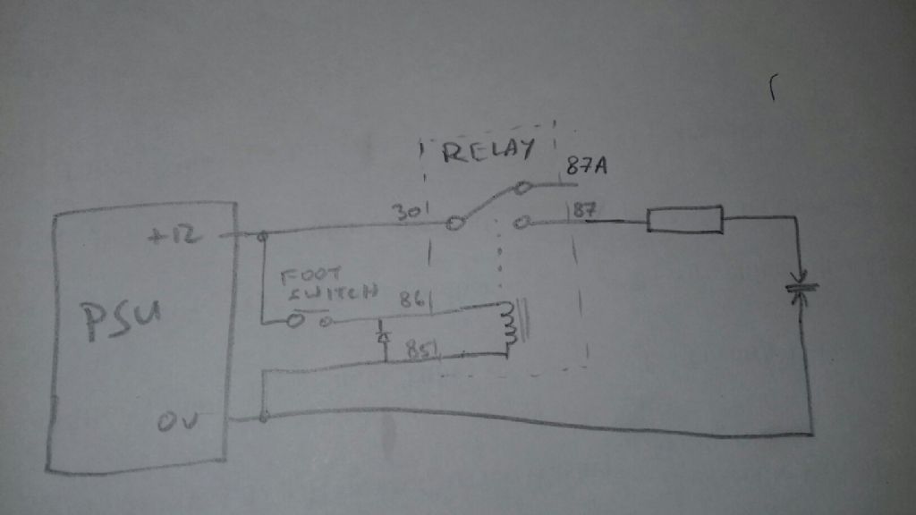
                      I actually managed to get hold of the electrical technician at the physics department. He kindly drew out this circuit diagram, and explained why each component (the relay is essential) is required for safe and reliable operation.

                      For simplicity of construction he recommends this design, obviously it's just a good ol' voltage divider. Attached his diagram below for reference in case anyone else fancies building an RSU.

                      rsu_dgm.jpg

                      #359032
                      SillyOldDuffer
                      Moderator
                        @sillyoldduffer

                        Trevor and Neil's suggestions are worth a try because they're cheap, but otherwise not ideal.

                        • Neil's Motor control units are pulse width modulated. The problem in this application is they don't reduce output voltage. Instead they switch on and off rapidly and the energy delivered to the motor is varied by changing the ratio between on and off times. This system works well on motors and filament lamps, but I think it's dodgy on a low impedance load like a resistance soldering unit especially if the electrode is moved. Say the electrode is 1ohm and you want 30W of heat: that's 5.5A at 5.5V. If instead you apply 10V across 1ohm, the power supply will deliver 10A or 100W continuous. To reduce that to 30W of heat, the PWM duty cycle would be 30%. So far so good but the energy is delivered in the form of 10V/10A pulses. I think this is undesirable because the extra volts are more likely to spark and the extra current more likely to arc. (Do you know what the resistance of your electrode is?)
                        • Trevor's suggestion is a buck unit. The trouble with these devices is they prefer to work into a steady load, which an RSU isn't. My feeling is that one would stall and/or burn out if used for any length of time on intermittent load. I've no idea what happens if you pair them up for extra current.

                        But hey, it's not going to break the bank if one or both ideas don't work out. Neither idea is unsafe. Be really good to know what happens in practice. Please give one or both ideas a go and report back.

                        If you can find or make one, the least troublesome way to do resistance soldering is with a suitable transformer. Shame that's getting hard &/or costly. There's a real need for a cheap alternative, so good luck.

                        Dave

                        Edited By SillyOldDuffer on 22/06/2018 18:08:32

                        #359035
                        SillyOldDuffer
                        Moderator
                          @sillyoldduffer
                          Posted by choochoo_baloo on 22/06/2018 17:55:14:

                          Thanks all for the replies.

                          I actually managed to get hold of the electrical technician at the physics department. He kindly drew out this circuit diagram, and explained why each component (the relay is essential) is required for safe and reliable operation.

                          For simplicity of construction he recommends this design, obviously it's just a good ol' voltage divider. Attached his diagram below for reference in case anyone else fancies building an RSU.

                          rsu_dgm.jpg

                          Except he's not covered the tricky bit which is the value of the resistor. It's going to get hot! What value should it be and is it practical? (Hope I've got it wrong – back of my envelope says 11 ohms radiating 350W to get 5.5A into a 1ohm electrode. )

                          Dave

                          #359038
                          Les Jones 1
                          Participant
                            @lesjones1

                            I think that using AC would give a simpler solution. obtain a toroidal transformer that is not filled with resin in the centre. The secondary voltage is not that important as you will wind a few turns of thick wire for the 3 volt secondary. From the figures you quote a 30 VA rated transfprmer should be enough but I suggest using at least a 60 VA one to give some power in reserve and also make it easier to wind the extra secondary. You can put a light dimmer in series with the primary so you can adjust the secondary voltage. You could use an old microwave oven transformer instead of a toroidal one but it will involve more work removing the high voltage secondary.

                            Les.

                            #359074
                            duncan webster 1
                            Participant
                              @duncanwebster1

                              If you're in the North West I can give you a toroidal transformer. It will have the wrong secondary voltege, but as Les says you can easily wind a few turns of thick wire to get 3 v. This all depends on being able to find where I've stached it away. Far too heavy to post

                              #359076
                              Simon Williams 3
                              Participant
                                @simonwilliams3

                                Let's do some simple arithmetic.

                                Original requirement was to provide RSU with about 3 volts, it would draw approx. 10 amps. So absorbed power is 30 watts. Possibly a bit light but it feels in the right ball park. Think of a 30 watt soldering iron – would this cut the mustard? Note the phrase " of the order of 10 amps" – properly this only says the current is somewhere between 1 amp and 100 amps! Need to nail this down a bit to do some meaningful calculations, so take the nominal values for the time being.

                                Equivalent resistance of the RSU is then 0.3 ohms (ish).

                                So we want to supply the RSU from a nominal 12 volt source. PSU needs to see 1.2 ohms total load for the load to draw 10 amps.

                                RSU accounts for about 0.3 ohms, so we need an additional 0.9 ohms in series with the RSU to end up with a circuit drawing 10 amps when supplied with 12 volts.

                                0.9 ohms isn't a preferred (standard, purchasable) value, so stick with 1.0 ohms as series ballast resistor for the time being. Moderates the load current to 9.2 amps.

                                Power dissipated by 1.0 ohm ballast resistor is 85 watts (I squared R), but only for the duration of the current flow. Suggest that the current flow will be less than 50% of the time, so average power dissipation is say 40 to about 50 watts. That said, the ballast resistor needs to have sufficient thermal mass that it doesn't reach its melt-down temperature during the time the current is flowing.

                                Suggest the ballast resistor needs to be one of those aluminium bodied plate mounted things, if you are going to buy one then stick with 100 watts dissipation, mount it on a moderate sized heat sink, try it and see. Remember that by adding a second resistor in parallel you reduce the overall value of the resistance, (product over sum rule for parallel resistances) and adding a resistance of 10 ohms in parallel will give you an effective resistance of (near enough) 0.9 ohms. The parallel trimmer resistance dissipates much less power – approx. 10 watts – so this "trimmer" resistor can be of a smaller power dissipation.

                                Putting two 1.0 ohm resistances in parallel halves the effective resistance i.e. 0.5 ohms, plus 0.3 ohms inside the RSU makes the load 0.8 ohms, supplied by 12 volts draws 15 amps, heading towards the max output of your fancy PSU. Dissipated power in EACH resistor is now 7.5 (volts) squared over 1.0 (ohms) equals 56 watts, but RSU terminal voltage rises to 4.5 volts. RSU absorbed power now 4.5 (volts) times 15 (amps) equals 68 watts, i.e more than doubled.

                                I've used the nominal 12 volts value of the input voltage so you can use the voltage adjustment of your "decent bench power supply" to fine tune the heat input.

                                Lots more arithmetic possible if we know the terminal characteristics of the RSU more accurately.

                                Hope this helps Simon

                                #359081
                                choochoo_baloo
                                Participant
                                  @choochoo_baloo
                                  Posted by duncan webster on 22/06/2018 20:03:58:

                                  If you're in the North West I can give you a toroidal transformer. It will have the wrong secondary voltege, but as Les says you can easily wind a few turns of thick wire to get 3 v. This all depends on being able to find where I've stached it away. Far too heavy to post

                                  Thanks for the kind offer Duncan. Unfortunately I'm in the south, so not possible to collect.

                                  #359084
                                  choochoo_baloo
                                  Participant
                                    @choochoo_baloo


                                    Posted by SillyOldDuffer on 22/06/2018 18:25:29:

                                    Posted by choochoo_baloo on 22/06/2018 17:55:14:

                                    Thanks all for the replies.

                                    I actually managed to get hold of the electrical technician at the physics department. He kindly drew out this circuit diagram, and explained why each component (the relay is essential) is required for safe and reliable operation.

                                    For simplicity of construction he recommends this design, obviously it's just a good ol' voltage divider. Attached his diagram below for reference in case anyone else fancies building an RSU.

                                    rsu_dgm.jpg

                                    Except he's not covered the tricky bit which is the value of the resistor. It's going to get hot! What value should it be and is it practical? (Hope I've got it wrong – back of my envelope says 11 ohms radiating 350W to get 5.5A into a 1ohm electrode. )

                                    Dave

                                    Thanks for your contributions Dave. I shall update this thread once it's assembled and I've done a few trials!

                                    He did describe the resistor value etc – I forgot to mention it above. I've ordered this 1.8 ohm power resistor (50W rating)

                                    https://uk.rs-online.com/web/p/panel-mount-fixed-resistors/1074096/?relevancy-data=636F3D3126696E3D4931384E525353746F636B4E756D626572266C753D656E266D6D3D6D61746368616C6C26706D3D5E285C647B362C377D5B4161426250705D297C285C647B337D5B5C732D2F255C2E2C5D5C647B332C347D5B4161426250705D3F292426706F3D3126736E3D592673723D2673743D52535F53544F434B5F4E554D4245522677633D4E4F4E45267573743D3130372D34303936267374613D3130373430393626

                                    Should also say (arguably the most important parameter of the RSU system) that I measured the carbon electrode to brass sheet resistance to be 0.4 ohm. Therefore:

                                    The nominal current is 12/2.2 = 5.5 A, yielding a dissipation across this ballast resistor of (5.5^2)*1.8 = 54W. The technician reiterated that small duty cycle (given that the circuit is only live for ~< 2 s at a time) means that the ballast resistor's rating of 50W is adequate.

                                    Finally, the "flyback diode" across the relay coil prevents a large voltage spike (and therefore arcing across the foot switch) by providing a way for the current flowing in the coil (which is an inductor) to dissipate harmlessly upon breaking the circuit.

                                    Edited By choochoo_baloo on 22/06/2018 21:22:53

                                    Edited By choochoo_baloo on 22/06/2018 21:23:25

                                    #359094
                                    SillyOldDuffer
                                    Moderator
                                      @sillyoldduffer
                                      Posted by choochoo_baloo on 22/06/2018 21:22:18:

                                      Posted by SillyOldDuffer on 22/06/2018 18:25:29:

                                      Posted by choochoo_baloo on 22/06/2018 17:55:14:….
                                      (Hope I've got it wrong – back of my envelope says 11 ohms radiating 350W to get 5.5A into a 1ohm electrode. )

                                      Dave

                                      Thanks for your contributions Dave. I shall update this thread once it's assembled and I've done a few trials!

                                      He did describe the resistor value etc – I forgot to mention it above. I've ordered this 1.8 ohm power resistor (50W rating)

                                      Should also say (arguably the most important parameter of the RSU system) that I measured the carbon electrode to brass sheet resistance to be 0.4 ohm. Therefore:

                                      The nominal current is 12/2.2 = 5.5 A, yielding a dissipation across this ballast resistor of (5.5^2)*1.8 = 54W. The technician reiterated that small duty cycle (given that the circuit is only live for ~< 2 s at a time) means that the ballast resistor's rating of 50W is adequate.

                                      Whoo whoo, looks good, your maths beats mine! One way of improving the cooling is to mount the resistor in a sealed 5L paint can full of new engine oil. Transformer oil is best, but any heavy oil (preferably without additives) will do. H&S common sense applies – don't boil the oil!

                                      Dave

                                      #359099
                                      John Haine
                                      Participant
                                        @johnhaine32865

                                        Why use DC in the first place? What you need is a chunky transformer with a mains primary and a few turns of thick secondary to generate a few volts but plenty of amps; then feed the primary from a variac to adjust the current. If you want to measure the actual current, get a current transformer, cheap enough from RS. Don't start messing with series resistors to control the current, they just get hot.

                                        #359113
                                        choochoo_baloo
                                        Participant
                                          @choochoo_baloo
                                          Posted by John Haine on 22/06/2018 22:34:37:

                                          Why use DC in the first place? What you need is a chunky transformer with a mains primary and a few turns of thick secondary to generate a few volts but plenty of amps; then feed the primary from a variac to adjust the current. If you want to measure the actual current, get a current transformer, cheap enough from RS. Don't start messing with series resistors to control the current, they just get hot.

                                          The department technician advised against any form of transformer meddling (I suggested re-winding a microwave transformer), When compared to my above circuit diagram, there's a lot to go wrong, degradation of windings if not properly sealed, fire risks. He said in professional jobs, he'd always discourage home-wound transformer.

                                          Most importantly using AC over DC would make the flyback diode (as I described previously) redundant which removes the this arcing protection for the foot switch contacts.

                                          Also, these power resistors are designed to comfortably handle these powers. I will also mount it on aluminium plate with thermal paste.

                                          #359179
                                          Ian S C
                                          Participant
                                            @iansc

                                            I was going to suggest that with most larger transformers there is usually enough room between the outer winding and the laminations to thread an extra secondary to give you the few volts that you need, but after reading your last post I won't. I did that with the large auto-transformer that supplies the 18V for my workshop power supply.

                                            Ian S C

                                            #359186
                                            Simon Williams 3
                                            Participant
                                              @simonwilliams3

                                              FWIW my feeling is that the model of the RSU as a simple linear resistor of a set value is probably over-simplistic. The actual current passed through the work will be dependent on surface oxide condition, clamp pressure and joint size, to name but a few of the potential variables in this device.

                                              On that basis there will be a better control over the current passed through the work with a series resistor, as the resistor controls the current more than the RSU does.

                                              Of course it's right to suggest that the power source could be AC rather than DC, but if I had a suitable DC PSU sitting on my bench I wouldn't bother to go raiding the microwave for its transformer. Not at the early stages of testing this procedure, anyway. Lash up something to get a taste of the success (or otherwise) of doing the soldering this way.

                                              Besides, SWMBO wants her porridge in the mornings, so I'm going to have to put the microwave back together a bit sharpish.

                                              Do please let us know how you get on.

                                              Simon

                                              #359210
                                              Michael Gilligan
                                              Participant
                                                @michaelgilligan61133

                                                Regarding AC vs DC … It's interesting to note that American Beauty uses only AC

                                                **LINK**

                                                http://www.international-tooling.co.uk/Pages/American_Beauty_Pages/ATI_Power_Units_All.html

                                                Whether for cost & convenience, or for technical superiority, I know not.

                                                MichaelG.

                                                #359213
                                                SillyOldDuffer
                                                Moderator
                                                  @sillyoldduffer

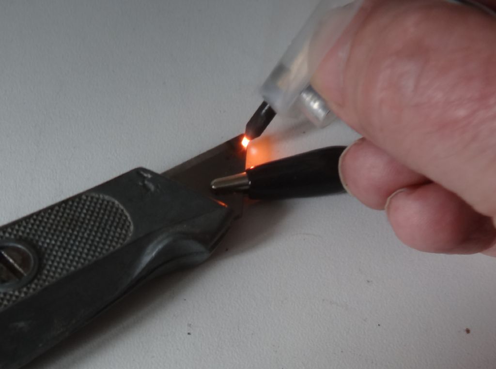
                                                  In the other RSU thread I suggested DC was undesirable because it increases the risk of arcing. The picture is 6VDC at about 1.2A, with the arc created by gently scratching the electrode along the blade. That little arc is hot enough to pit stainless steel.

                                                  arc.jpg

                                                  ChooChoo mentioned an advantage of AC being elimination of the diode across his relay coil.  Similar problem; an inductive spark risks creating an arc that welds the footswitch contacts together when they switch DC.  (Not very likely I admit.)

                                                  Dave

                                                  Edited By SillyOldDuffer on 23/06/2018 18:37:39

                                                  #359265
                                                  Michael Gilligan
                                                  Participant
                                                    @michaelgilligan61133

                                                    Here's something for you to contemplate, Dave:

                                                    Decades ago, I was given an 'XP Welder' <phew, glad I didn't pay for it>

                                                    This contraption, which was also marketed as the 'Rawlplug Welder's Mate' , allowed one to arc weld [using flux-coated rods] using car batteries … The handle included a buzzer solenoid which kept the arc going, and avoided sticking.

                                                    The interesting bit is that it also featured the facility to mechanically lock-out the buzzer … a carbon rod then replaced the welding rod, to allow resistance brazing.

                                                    MichaelG.

                                                    #359275
                                                    SillyOldDuffer
                                                    Moderator
                                                      @sillyoldduffer
                                                      Posted by Michael Gilligan on 24/06/2018 07:10:30:

                                                      Here's something for you to contemplate, Dave…

                                                      MichaelG.

                                                      Yes, I believe you. Used with care, I think it could be done safely.

                                                      Nothing to to with Resistance Soldering, but reading about arcs led me to this fascinating paragraph on Wikipedia:

                                                      Arc flash is distinctly different from the arc blast, which is the supersonic shockwave produced when the uncontrolled arc vaporizes the metal conductors. Although both are part of the same arc fault, and are often referred to as simply an arc flash, from a safety standpoint they are often treated separately. For example, personal protective equipment (PPE) can be used to effectively shield a worker from the radiation of an arc flash, but that same PPE may likely be ineffective against the flying objects, molten metal, and violent concussion that the arc blast can produce. (For example, category-4 arc-flash protection, similar to a bomb suit, is unlikely to protect a person from the concussion of a very large blast, although it will prevent the worker from being vaporized by the intense light of the flash.)

                                                      Health & Safety gone mad! In the good old days chaps were protected by nothing more than a flat cap, and they were happy to be vaporised at work. Apprentices were blown up twice a day unless the foreman fancied them.

                                                      smiley

                                                      Dave

                                                    Viewing 25 posts - 1 through 25 (of 30 total)
                                                    • Please log in to reply to this topic. Registering is free and easy using the links on the menu at the top of this page.

                                                    Advert

                                                    Latest Replies

                                                    Viewing 25 topics - 1 through 25 (of 25 total)
                                                    Viewing 25 topics - 1 through 25 (of 25 total)

                                                    View full reply list.

                                                    Advert

                                                    Newsletter Sign-up