Demagnetiser

Advert

Demagnetiser

Home Forums Electronics in the Workshop Demagnetiser

Viewing 22 posts - 1 through 22 (of 22 total)
  • Author
    Posts
  • #207285
    AndyP
    Participant
      @andyp13730

      Since I suffer from the curse of magnetised tools I was pleased to see this in MEW 234 and the circuit looked simple enough for me. The design calls for a 60w bulb to limit the current flowing but my transformer has been liberated from a dead cordless drill battery charger whose rating plate said 18 volts at 2 amps for the output so do I need to keep the bulb's power under that?

      I suspect that in my chaotic workshop an exposed bulb like that will have a life expectancy measured in hours rather than months so is there any other simple method of regulating the current drawn.

      Cheers, Andy

      Advert
      #31804
      AndyP
      Participant
        @andyp13730
        #207298
        TobaccoBurner
        Participant
          @tobaccoburner

          Bit of a suck it and see exercise since we don't know the inductance of the modified transformer or the resistance of the lamp ( it varies with filament temperature ). I would guestimate that the original charger primary current was around 200 milliamps so this is your target. I would suggest maybe start with a 40W lamp, measure the current and see how hot it gets then adjust as necessary. Nothing will melt instantly.

          Incidentally I would enclose the lamp in a substantial cage or tin can with ventilation holes. With the current setup, if you break the glass, you have wires carrying 240V waving in the breeze. I just hope the author has a fully functional RCD on his supply.

          Mike

          #207301
          Michael Cox 1
          Participant
            @michaelcox1

            Hi Andy,

            No need to worry about the the different transformer it will work well in the same circuit but reduce the bulb to 40 watts.

            I agree that the lamp should be shielded for safety. An old soup can with a hole in the bottom serves on my unit. I did not show it in the photo of the unit because I wanted to show the bulb.

            Mike

            #207399
            Ian S C
            Participant
              @iansc

              Here's my demagnetiser, the coil in the box is one removed from the transformer from a micro wave oven, the transformer that powers it came from an electric blanket, the HI setting is 12V, and LOW is 6V.

              Ian S Cdsc00682 (640x480).jpg

              #207407
              John Shepherd
              Participant
                @johnshepherd38883

                I was in the workshop last week and every tool I used seemed to be magnetised for some reason and I promised myself I would move the demagnetiser project to the top of my to do list. Stopped for lunch and lo and behold MEW dropped through the letterbox with the demagnetiser article inside.

                I set out modifying a transformer similar to the one in the article and did a quick test without the current limiter lamp and with a 3A fuse in the plug and it worked Ok. I have measured the AC current at 240v and it is about 0.5A. As expected with the 'I' laminations removed the transformer does get hot after several seconds so a push button is a must and the duty cycle needs to controlled. Although the current limiter is good practice, I am willing to give it a try without, but as soon as I get the box to mount it in, I will be fitting a resettable thermal fuse on the windings and a neon to show if it has tripped or not.

                (Note I would not take this risk with a heavier duty transformer or an ex microwave one)

                Regards

                John Shepherd

                #207423
                Muzzer
                Participant
                  @muzzer

                  The inductance with the laminations removed must be minimal, so the DC resistance of the primary must be of the order of 500 Ohms if the current is limited to just 0.5A – any means of measuring with a multimeter to check? The load regulation if the original transformer must have been pretty poor. That's a simpler and neater solution than messing about with bulbs etc.

                  #207426
                  Ajohnw
                  Participant
                    @ajohnw51620

                    I've used one of the small electric ones jewellers watch repairers use for tool bits. They are pretty cheap on ebay.

                    John

                    #207429
                    John Shepherd
                    Participant
                      @johnshepherd38883

                      Muzzer

                      The measured inductance of the demagnetiser is 936mH and the resistance is 231R. A similar sized unmodified transformer measures 232R and 2.4H.

                      #207435
                      jason udall
                      Participant
                        @jasonudall57142

                        Pardon me if I am missing something.

                        You are taking a mains tranaformer..
                        Dissembling it ..retain primary. ..( possibly remove secondary)..reassemble laminations..in E form..

                        Now tell me how this.. apart from damage during dissembling. . is going to behave less safely than before?

                        Edited By jason udall on 11/10/2015 17:43:01

                        #207504
                        Ian S C
                        Participant
                          @iansc

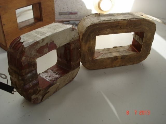
                          Got a photo here of the windings as removed from the micro wave transformer. There is no need to use more than 12V in a small (or even quite a large demagnetiser of this type. Either coil will do

                          Ian S Cdsc00683 (640x480).jpg

                          #207516
                          John Rudd
                          Participant
                            @johnrudd16576

                            A posistor may be a suitable replacement for the light bulb…..

                            Anyone familiar with repairing tv's may well have come across them before ( certainly had my fill of duff ones…..)

                            Basically it comprises of a heating element strapped across the mains and a ptc element in series with the load,both being coupled together physically in the same package; in this case the degaussing coils….On switch on, the heater is cold but begins to warm, at the same time, the ptc element has a low resistance, the current through the degaussing coils is limited by this….As the heater warms, it affects the resistance of the ptc device, causing its resistance to increase in value thus reducing the current flow….

                            This effect could be used in this application?…..just a thought…

                            #207520
                            Ian P
                            Participant
                              @ianp
                              Posted by jason udall on 11/10/2015 17:41:58:
                              Pardon me if I am missing something.

                              You are taking a mains tranaformer..
                              Dissembling it ..retain primary. ..( possibly remove secondary)..reassemble laminations..in E form..

                              Now tell me how this.. apart from damage during dissembling. . is going to behave less safely than before?

                              Edited By jason udall on 11/10/2015 17:43:01

                              If only life was so simple Jason

                              There is no real or simple why the end result will be any less safer but a lot depends on the skill and knowledge of the person doing the modification.

                              A lot of transformers are just not suitable for being adapted because of such things as all windings on one bobbin, laminations bonded or welded together, presence of a built in thermal fuse etc.

                              One thing in favour (from a safety aspect) of the current MEW project is that if all else fails the lamp will prevent any damage. Removing half the laminations will significantly change the magnetic circuit so its a guess how much current the demagnetiser will draw from the mains. The one shown in MEW looks to be quite a low power demagnetiser and I would be tempted to use the transformer direct to the mains via a push button switch that is then only held down for a few seconds at a time allowing the transformer to cool down between objects.

                              Ian P

                              #207532
                              AndyP
                              Participant
                                @andyp13730

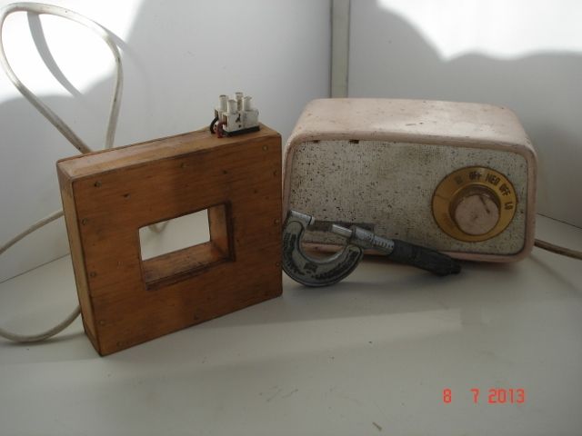
                                I freely admit that the land of the magic smoke is not my normal abode so a lot of the above has gone well over my head but this is the transformer I have dismantled and removed the secondary windings from and re-assembled as per the articles instructions.

                                transformer

                                The connections are the original mains cable the middle position being vacant.
                                If I use my little digital multi-meter on the connections everything is open circuit except between the vacant centre terminal and live. That makes me think this transformer is NBG is that correct?

                                Andy

                                #207539
                                Michael Cox 1
                                Participant
                                  @michaelcox1

                                  Hi Andy,

                                  If there is an open circuit across the original primary connection then I think you are correct in assuming the transformer is NBG.

                                  Don't eat to much cow pie it might make you desperate!

                                  Mike

                                  #207564
                                  AndyP
                                  Participant
                                    @andyp13730

                                    Thanks Mike,

                                    Just to satisfy my curiosity I took the cover off the primary winding and found a small square black component between the centre terminal and neutral, the actual windings are terminated on the two connections I measured 47 ohms on so maybe it isn't a lost cause, just got to rescue the stack of E plates from the bin!
                                    The component has the following legend:- A3 AUPO Q2 125C JET 2A 250V so I suspect that tells you what it is, it is open circuit whatever it is.
                                    Cow pie – that's my Desperate Dan tea mug, my kids think they are comedians!

                                    Andy

                                    #207568
                                    Ian P
                                    Participant
                                      @ianp

                                      The component you describe is almost certainly a non resettable thermal fuse. Set to open at 125 degrees C and rated to carry 2A continuously.

                                      What is does tell you though is that at some time your transformer has been hotter than it should! The fuse though will have prevented any winding damage and certainly if you have the limiting resistor (lamp) then it should be quite safe to use.

                                      I originally suggested it might have a fuse but you had said that the photo showing the mains terminals and wiring was original but I could not see any connections.

                                      Ian P

                                      #207577
                                      AndyP
                                      Participant
                                        @andyp13730

                                        Ian,

                                        Cheers, that will explain why the battery charger it came out of stopped working then. In that photo the component is wired across the leftmost two terminals, the winding across the rightmost two but it was hidden under the tape wrapped round the windings which is itself under a plastic cover so not obvious unless you know it might be there.

                                        Andy

                                        #216106
                                        Frances IoM
                                        Participant
                                          @francesiom58905

                                          I started to construct the demagnetiser suggested by Mike Cox in MEW but on disassembly found that the primary was open circuit (tho thermal fuse seemed ok) – the source being one of those 25W small halogen lights on telescopic arms sold (and possibly still are) by WH Smiths, B+Q etc – didn't check the transformer as thought the failure as a lamp was due to the failure of the non-repairable on/off switch embedded in the hemispherical cover

                                          demag.jpg

                                          however the secondary winding was fine – the base was removable and was already provided with screwfittings for the transformer which just needed a mdf spacer to replace the removed I laminations

                                          Powered from an old 6V battery charger with a 1ohm 10W resistor(ex Maplins) fitted to limit current to about 2A – the 3 bits of spare MDF easily cut to form a case – the only got-cha I realised was that the terminals needed to be isolated from the case just in case came into contact with on of the charger leads and shorted the rectifier hence the use of 2 4mm terminals rather than the planned barrel connector

                                          No problems with mains or the use of empty soup tins!

                                          #216109
                                          Ian P
                                          Participant
                                            @ianp
                                            Posted by Frances IoM on 12/12/2015 21:33:42:

                                            I started to construct the demagnetiser suggested by Mike Cox in MEW but on disassembly found that the primary was open circuit (tho thermal fuse seemed ok) – the source being one of those 25W small halogen lights on telescopic arms sold (and possibly still are) by WH Smiths, B+Q etc – didn't check the transformer as thought the failure as a lamp was due to the failure of the non-repairable on/off switch embedded in the hemispherical cover

                                            demag.jpg

                                            however the secondary winding was fine – the base was removable and was already provided with screwfittings for the transformer which just needed a mdf spacer to replace the removed I laminations

                                            Powered from an old 6V battery charger with a 1ohm 10W resistor(ex Maplins) fitted to limit current to about 2A – the 3 bits of spare MDF easily cut to form a case – the only got-cha I realised was that the terminals needed to be isolated from the case just in case came into contact with on of the charger leads and shorted the rectifier hence the use of 2 4mm terminals rather than the planned barrel connector

                                            No problems with mains or the use of empty soup tins!

                                            Unless I have misunderstood, or missed something really obvious I'm not sure how your demagnetiser works!

                                            Demagnetisers work by producing a rapidly reversing magnetic field from an 'AC' source. If the charger has a rectifier in it than it produces DC so will in fact magnetise all you tools.

                                            Ian P

                                            #216110
                                            Frances IoM
                                            Participant
                                              @francesiom58905

                                              sorry thought obvious I merely tapped across the 8v winding on the transformer (hence my comment re possible short circuit of one arm of the bridge rectifier (an old selenium rectifier the smell of which when fried is not pleasant) – thus fed by low voltage 50Hz!

                                              #216125
                                              Martin Connelly
                                              Participant
                                                @martinconnelly55370

                                                Why not feed the demagnetizer coil with the AC from another transformer? This will be a safe way of limiting the current in the demagnetizer coil and be more robust than a lamp bulb.

                                              Viewing 22 posts - 1 through 22 (of 22 total)
                                              • Please log in to reply to this topic. Registering is free and easy using the links on the menu at the top of this page.

                                              Advert

                                              Latest Replies

                                              Viewing 25 topics - 1 through 25 (of 25 total)
                                              Viewing 25 topics - 1 through 25 (of 25 total)

                                              View full reply list.

                                              Advert

                                              Newsletter Sign-up