Hi there, Alex and Peter,
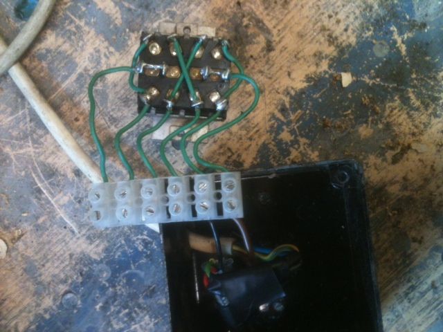
Peter, the rear view of the switch is shown in Alex' second photo. It looks to me like an ex-USA WW2 surplus component – a four pole change-over toggle switch with centre off. I have one on my bench drill control box.
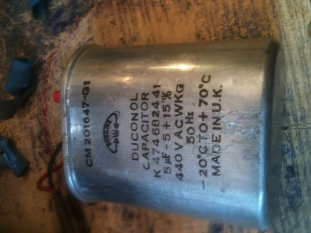
The wiring shown in photo #2 looks to me as though the mains input should connect to the two strapped pairs of the centre contacts, the running winding of the motor to the outer contacts and the motor start winding (& series capacitor) to the inner contacts (strapped as X).
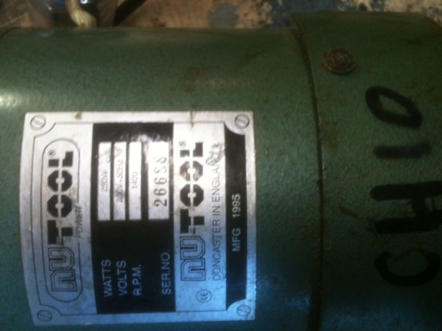
The switch contacts are probably OK for the motor running current (1/3 HP) but I'd advise against using that switch for on-off control, fit a single phase direct on-line starter with built-in no-volt release up-stream of the toggle switch. (See various threads on this forum concerning the Dupar drum reversing switch.)
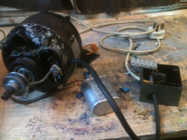
The motor frame and mounting bracket and the switch enclosure case must be bonded together and earthed via an adequate size cable.
If the toggle switch has a light coloured plasic insert in the outer end of the toggle, take care – they are filled with a radium-based luminous paint. The phosphor (zinc sulphide or similar) 'wears out' but the radium-based exciter ingredient of the paint has a sufficiently long half life to still warrant care, even this long after WW2! It's OK as long as it's contained but DON'T take it to pieces!!! There was extensive discussion of WW2 instrument luminous dials in the Amateur Radio literature a few years ago.
Best regards,
Swarf, Mostly!
Alex Hunt.


