Hi folks, some interesting thoughts there.
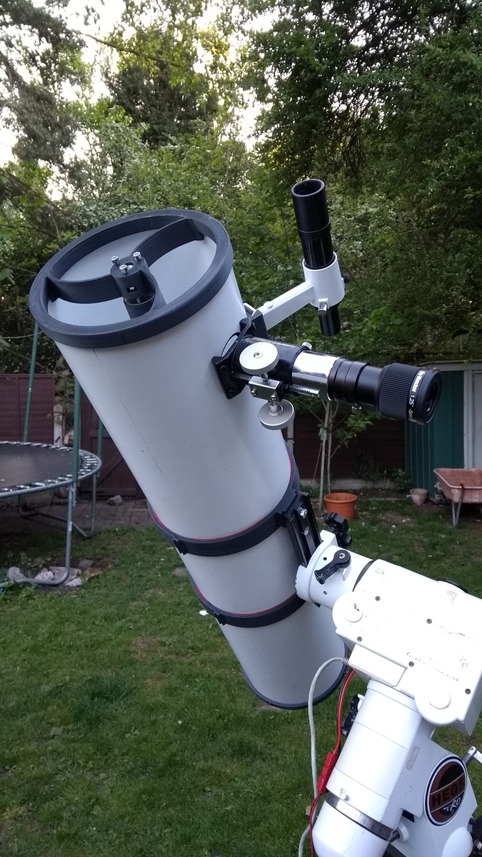
@Jeff the little spikes idea is a good one. I've devised a few different clips and joiners, and I use a lot of thread direct in the print, just tapping a thick walled print for small threads and M6 up printing them direct. The spider is secure as a clip on fit, the base with the mirror is heavier so had four tapped holes for M4 screws through the tube, just in case. I once printed a cubical maze, with a captive 10mm ball bearing inside.
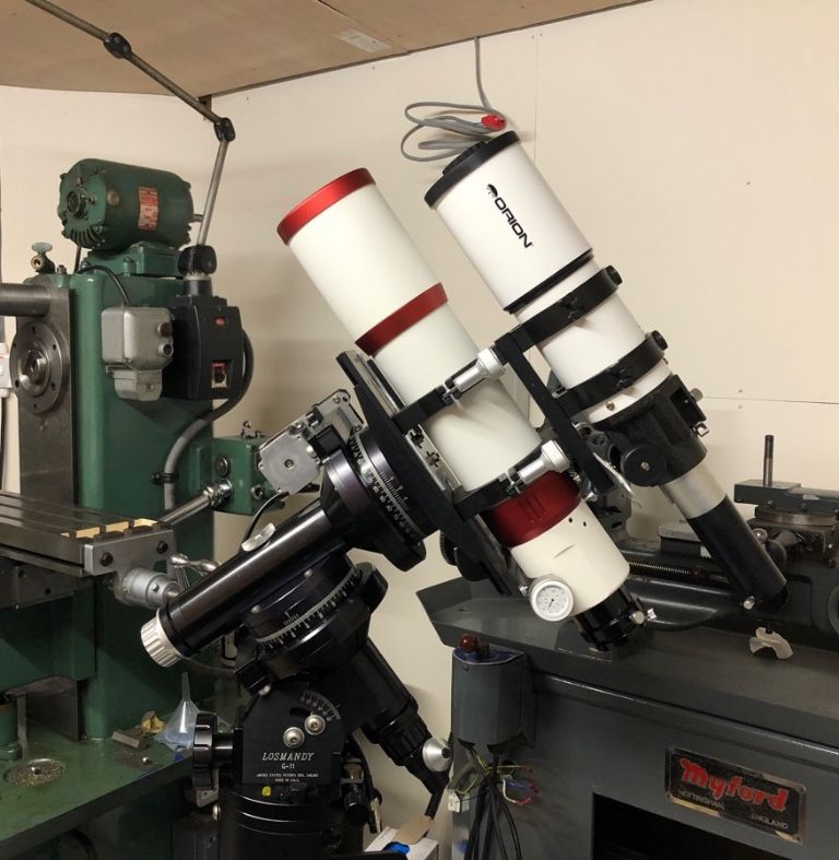
@Joe the curved spider is designed so the angles add up to 180 degrees, as each spike is double sided this spreads the pattern over a full circle making the diffraction spikes you get with straight vanes disappear for a tiny cost in contrast. the mount is a German equatorial mount which you align to the pole star so it moves in RA and EC. That one is capable of being guided (with an ancillary scope) to an accuracy of 0.6 arc-seconds for astrophotography.
@Ed I will use self-adhesive flock on the top end of the tube and paint the lower end with matt black stove paint (ordinary matt black reflects IR so is poor for photographic use).
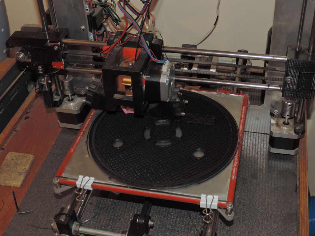
@Peter I have a Prusa i3 clone built from a kit which is no longer available. I have extended the Y-axis to allow me to print up to ~205mm diameter. For these prints I uses a 0.4mm nozzle and 0.2mm layers, the material is Monoprice PLA Plus which is excellent for this sorts of thing as it gives very clean prints. It does have two flaws – it's layer adhesion isn't as high as ordinary PLA unless printed very hot (which tends to make it stringy) so poor for parts subject to bending like spring clips, although strong enough for parts like this where loads are spread out a bit. It's other flaw is it isn't good for big overhangs (e.g. the bow of a '3D Benchy test model).
@Martin life may be too short as I have so many hobbies but I would like to make a big mirror one day, which would mean things like Ronchi tests. As my scopes have all been built around existing optical elements my measurements have been restricted to determining focal length (or radius of curvature for a mirror, which is twice focal length). hat was a nice experiment – just creating an illuminated crosshair in the middle of a screen and setting the mirror to project an in-focus image of the cross hair back on the screen. The tape measure distance was 72", so the focal length is 36". It's a 6" mirror so that's f6, a nice balance between light gathering and susceptibility to coma, which affects faster mirrors.
@Steve the first quarter evening moon is reversed in Southern Hemisphere with the light part on the left, and vice versa for the last quarter early morning moon.
I still want to make some changes, I'm waiting for M5 30mm grub screws for adjusting the secondary mirror. The temporary M4 bolts are not only loose in the holes which makes adjustment hit and miss, they protrude out the end and are vulnerable to knocks. I've also found the main mirror collimation adjusters (25mm diameter knurled nuts) are easy to knock when pointing the scope. Most scopes have lock screws so I'm going to reprint the base so it takes three of the M5 grubs with captive nuts for this purpose – then only one Allen key for everything.
And as I'm reprinting, I will put a circular shrouds around each adjuster which will also act as feet.
It will be a 13-14 hour print with those changes! Picture below is printing the first version of the end cap which includes a light-baffled vent.
The nice thing about this is that once 'perfected' the parts will suit any 6" mirror set, you will just need to reduce an 8" ventilation duct down to 7" (you can use the printed parts as a jig, I worked the other way round) and cut it to the correct length for the mirror/focuser combination.
Phew, there's so much going on with this I might stretch it into an article for MEW!
Neil

Enough!.


