Creality 3D For Christmas – Impressions so Far

Advert

Creality 3D For Christmas – Impressions so Far

Home Forums 3D Printers and 3D Printing Creality 3D For Christmas – Impressions so Far

Viewing 25 posts - 1 through 25 (of 116 total)
  • Author
    Posts
  • #31620
    SillyOldDuffer
    Moderator
      @sillyoldduffer
      Advert
      #443497
      SillyOldDuffer
      Moderator
        @sillyoldduffer

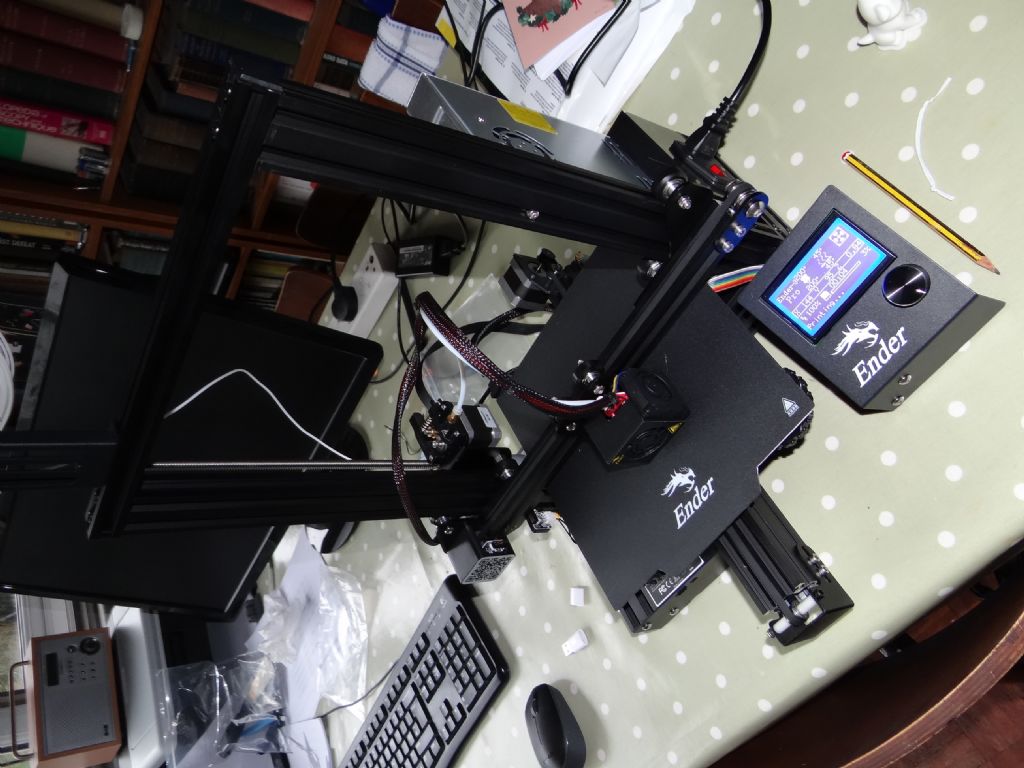
        Bought myself a Creality Ender 3-Pro printer for xmas and thought I'd report progress. I chose the model based on good reports – it's the go to choice at the moment for a low cost starter. Arrives as a part built-kit, fairly basic, but allegedly produces reasonable results. (Sorry about orientation!)

        dsc06180.jpg

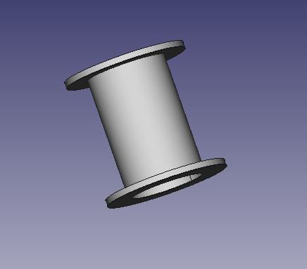
        I want the printer to produce small plastic components for other projects. For example, I'm crawling towards building a small horizontal steam engine with Arduino controlled electric valve gear. I'm interested to see what the engine will do with four independent valves providing total flexibility over valve events, allowing experimentation with lead, lag, expansion and timing etc without having to rebuild mechanical valve gear. I intend making 4 solenoid steam valves myself, mostly brass, but with a purpose made plastic coil former.

        bobbin.jpg

        Also interested in the practicalities – strength of 3D objects, overhangs, dimensional accuracy, software, and how long it takes to make something for real. (5 minutes or 10 days!)

        Anyway, the printer took about an hour to assemble and another two to debug due to some spanner mixing a pair of plugs & sockets up.

        blush

        More coming…

        #443498
        SillyOldDuffer
        Moderator
          @sillyoldduffer

          Although assembly isn't complicated, I found the instructions to be a shade too minimal. There's a single sheet self-build furniture style picture sequence showing how the parts join together. Then the new owner has to find the Operating Manual and Troubleshooting Guide. The Troubleshooting Guide looks quite good, but the Operating Manual is also a shade too terse for me. Nonetheless, I got the printer to power up without having to seek advice on the Internet.

          In preparation I'd drawn two test objects with FreeCAD. The workflow is:

          • Create the object by extruding 2D sketches into 3D objects as usual with FreeCAD (Much the same as other 3D CAD)
          • Export the object as an STL File. STL is short for 'Stereolithography', and is a common way of describing the shape of 3D objects.
          • Import the STL file into Creality Slicer; this is a Windows application provided with the Printer. It 'slices' 3D shapes into multiple layers, bottom up, and outputs the gcode needed to control the printer (or other CNC machine).
          • Copy the gcode file to a memory card held in a USB converter (both provided(
          • Switch on the printer, level the bed, and zero the print head.
          • Warm up the print-head and feed plastic stock (provided) into the mechanism until a little plastic blobs out of the print nozzle.
          • Set the print-head to 200C and the bed temperature to 45C
          • Insert the memory card with gcode into the slot provided. The contacts face UP!
          • Follow the slightly confusing instructions for Printing via menu option 'Init TF Card', and a list of what's on the card should appear on screen. Select the wanted gcode file. (Although I had no problem reading it with Windows and Linux, I had to reformat the supplied memory card before the printer recognised it.)
          • Watch the head and bed temperatures take a few minutes to rise, before printing starts by laying down a foundation layer.
          • Wait a very long time for printing to finish!

          The Creality Ender 3 Pro is a slightly improved version of the popular Ender 3. The pro comes with a stiffer frame, better base, beefier power supply, and a flexible magnetic plate that sits on the hot bed. The latter makes it easier to get models off the printer bed – no need for Hairspray or other tricks. Not everyone thinks these goodies are worth the extra money, but the magnetic plate works well for me.

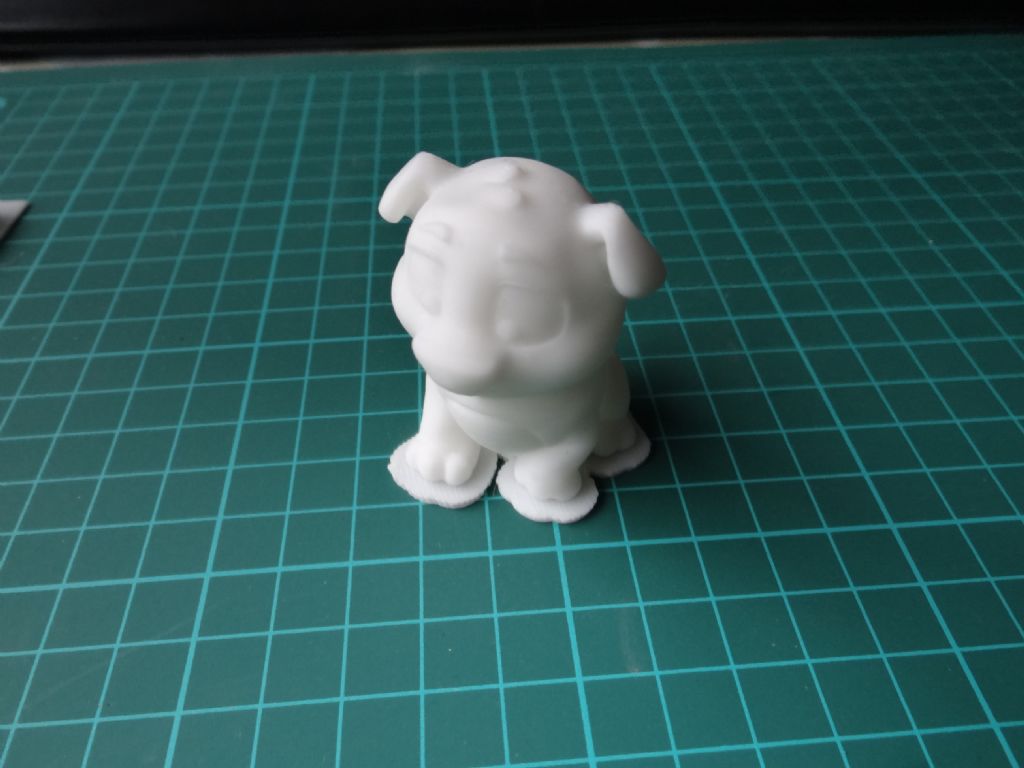
          First model is the dog supplied by Creality to test the printer. Although I don't want a dog, I printed one to see how well the printer would behave with a model supplied by the seller. It should be good, and it was.

          dsc06186.jpg

          Apart from taking 3 hours to print!

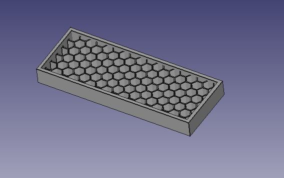
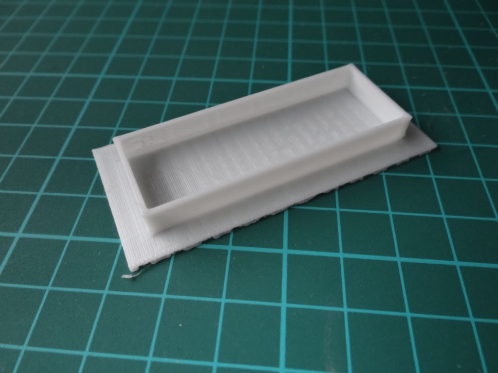
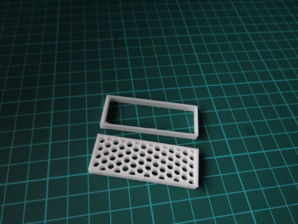
          Next, I tried a home-designed honey-comb structure intended to see how well the printer would cope with a fine internal structure.

          honey.jpg

          Didn't work properly, checking back there's an error in the honey-comb section of my FreeCAD model. However, the outer frame printed OK. Specified to be 58.38mm x 21.75mm, it printed as 58.2 x 21.7mm.

          dsc06185.jpg

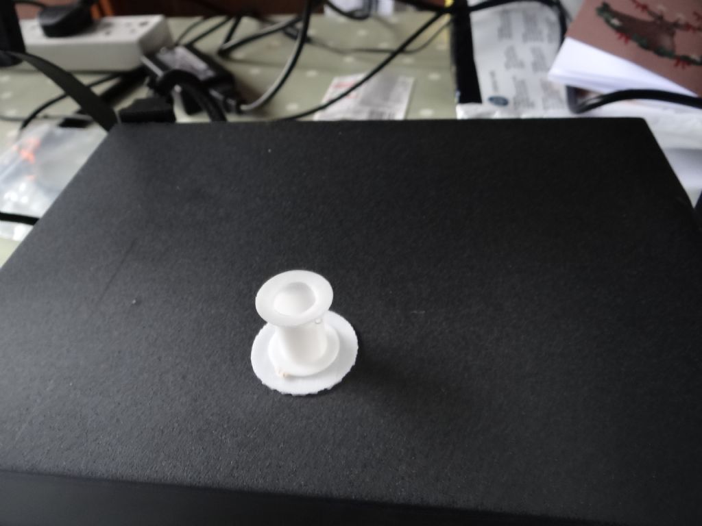
          Next was the coil bobbin needed for my solenoid valves. This is 20mm diameter, 20mm high, with a 12mm diameter hole. All surfaces are 1mm thick.

          This printed well in 21 minutes, and I was particularly pleased to see a reasonable top-plate – I expected it to sag, but the software was intelligent enough to build the overhang in sensible stages. Dimensionally quite good; 20.00mm base diameter, 20.03 top diameter. The centre hole is most faulty, a rim formed narrowing the 12mm interior to 11.52mm at the very top.

          The dog is near perfect The most obvious problem with the honeycomb and bobbin are the solid raft laid down first, which will have to be removed. The raft must be a software feature. The bobbin has a minor flaw due to a blob of plastic building up on the print nozzle. The underside of the top-plate is slightly untidy, but the bobbin is perfectly serviceable.

          dsc06188.jpg

          Conclusions: Pretty impressed for the money. Not ultra-accurate and printing takes ages. No problems on the software side that can't be blamed on me. Objects are likely to come off the printer needing some remedial work. There's a lot more to learn.

          Dave

          #443499
          Lainchy
          Participant
            @lainchy

            Great to see you have success Dave. There sure IS loads to learn, but take it steady and try adjusting one bit at a time. For doing my own prints, I always undersize by 0.2mm and that seems to come out pretty well using SunLu PLA+, but this is very design/material and machine specific.

            Lots of test prints… and you'll be bang on. Octoprint is WELL worth setting up too

            Enjoy and Happy new year

            Ian

            #443505
            Steve F
            Participant
              @stevef

              Hello

              Glad to see you having some fun. It is a huge learning curve. Small holes allways come out smaller than intended and may need to be larger 0.2mm say than the size you want in the 3d design. Outside sizes are normally ok.

              The most important step to take is calibrate the extruder e-steps and then find a flow rate o match the roll of filament you are using. The esteps is done once only and matches the filament size to the knurled extruder wheel but the flow rate will vary from roll to roll of filament even of the same type.

              Size problems come from over / under extrusion. To much will make a part come out bigger.

              No need to calibrate X or Y

              regards Steve

              #443510
              Pete Rimmer
              Participant
                @peterimmer30576

                I drew a test cube for mine 20mm cubed with a 12mm hole through it. The cube came out 20.15 at it's worst and 20.05 best. The hole was 11.75 or so.

                I think your honeycomb didn't print because the edges were too thin to be 'recognised', What thickness did you draw the walls of the cells?

                #443511
                Anonymous

                  Looking good! thumbs up

                  What material are you using? To some extent size errors are due to the material shrinking as it cools. For PLA I find that a good starting point is to scale by 1.005, ie, half a percent. Thin walls print best if they are a multiple of the nozzle size. My nozzle is 0.4mm so I chose 0.8mm, 1.2mm and so on. A raft or brim helps the first layer to adhere. It's usually controlled in the slicing software.

                  Andrew

                  #443565
                  I.M. OUTAHERE
                  Participant
                    @i-m-outahere

                    Hi Dave ,

                    Looks like you got that printer sorted out pretty quickly !

                    My Geeetech took a lot longer than that but i think the biggest problem was me ! I knew nothing about printers , slicers or cad so i had 3 fairly sharp learning curves to deal with !

                    May i suggest a simple test that should be done on all printers when new and that is test the thermal runaway settings , it is a simple matter of disconnecting one of the thermistor wires on the hot end and bed and try to heat them up -you should get a fault warning on the display and the heating should be terminated . This is required so if a thermistor dies or a wire breaks the heating is stopped and your printer won’t burn your house down !

                    It should be enabled already but it is always worth checking !

                    #443570
                    Martin King 2
                    Participant
                      @martinking2

                      Hi All,

                      I also treated myself to one of these just before Xmas and the initial setup was OK until testing time when the z axis was found to be binding.

                      Found an excellent YouTube source for a careful rebuild: The Edge of Tech

                      Then printed the dog which was perfect. Went on to do the top plate for a small tripod which was good but though holes a little undersized. Will post some pics after the new yea when we get back home.

                      Overall very impressed with the unit.

                      Happy New Year to ASll!

                      Martin

                      #443585
                      Pete Rimmer
                      Participant
                        @peterimmer30576

                        I had to shim the z-axis mount and drill the holes a little to allow for a tiny bit more adjustment. Once I did that I could get the screw parallel to the post. Another thing to make sure of is not to tighten the z-axis nut too much. It cocks over and binds the screw a little.

                        #443591
                        SillyOldDuffer
                        Moderator
                          @sillyoldduffer

                          Not being very methodical this morning; I'm watching another attempt to print my honeycomb object fail. The original object was drawn (with an error) and sliced on Window10 with FreeCAD and Creality Slicer. Now testing with FreeCAD (drawn with no errors) and Cura on Ubuntu 19.10 All working apart from the fine honeycomb centre.

                          honey.jpg

                          As the walls are only 0.25mm thick, Pete's suggestion that they are too thin to be recognised seems highly likely.

                          Back to the drawing board!

                          Observations:

                          Works equally well on Linux and Windows. Might steal daughter's Apple for testing later…

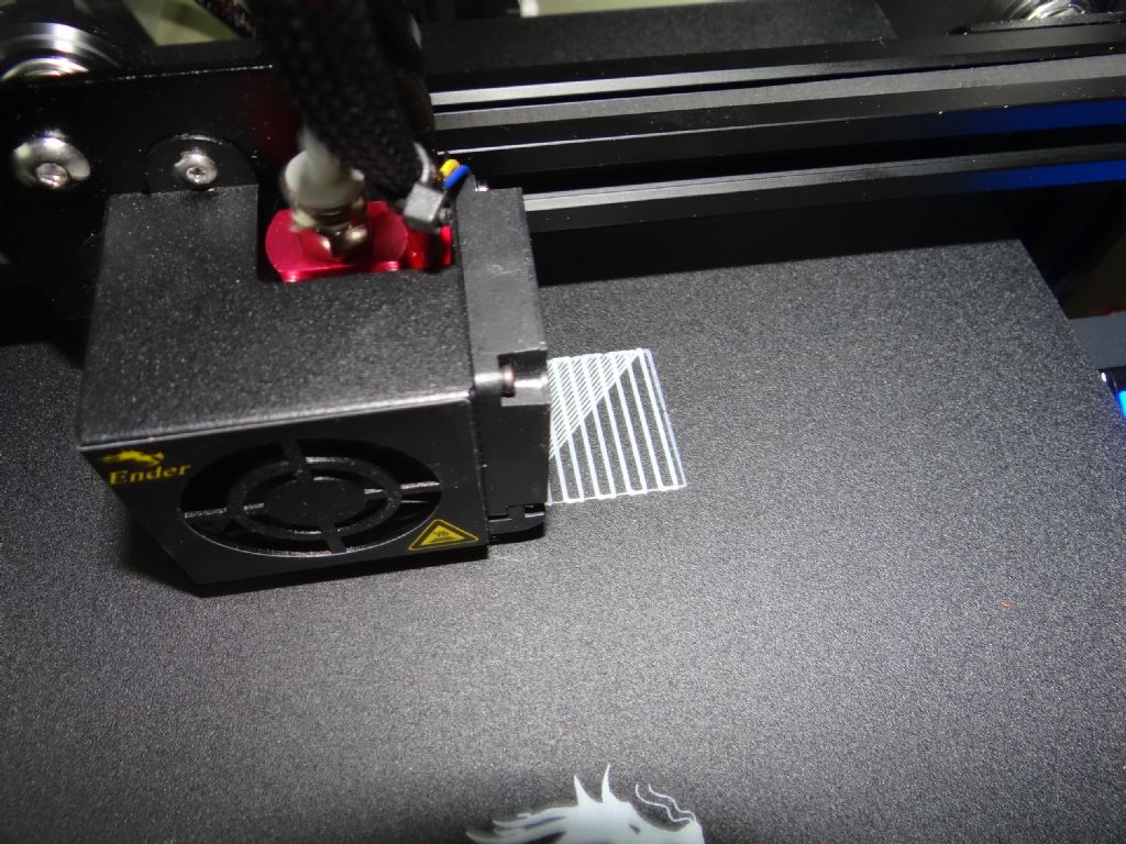
                          Creality's Slicer and Cura are remarkably similar, except Cura has more control making it slightly harder to drive. At the moment I'm using both out-of-the-box without playing with any of the settings. I got both slicers to work without reading the manual! By default Creality's slicer lays down a solid bed as shown developing below:

                          dsc06178.jpg

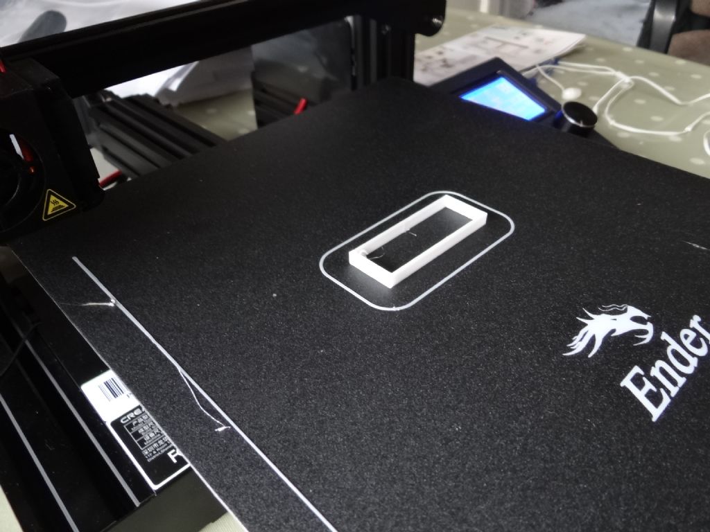
                          In contrast, Cura starts by clearing the nozzle by drawing a long line along one side of the bed, then draws an oval, and then prints the object directly on the table. The gcode that squirts start-up plastic is accessible if I decide to change it.

                          dsc06192.jpg

                          Having read it's more forgiving than other filament plastics, I'm printing with PLA.

                          So far I've found this considerably easier than expected. I would like to put success down to me being a genius, actually Creality have sold me a junior hobby printer that doesn't need a lot of complicated setting up and calibration. It's more consumer-friendly than earlier hobby printers and hasn't baffled me with clever features. (I may regret the lack of advanced features later.)

                          What next? Thanks to suggestions I'm spoilt for choice. Fix the honeycomb following Andrew's advice about nozzle size I reckon, then give OctoPrint a try, thanks Ian. Despite 3 fans, 4-stepper motors and being unboxed the printer isn't particularly noisy. But it gets irritating after a while, and the machine emits enough RF to flatten my DAB Radio a metre away. (It's fine 3 metres away.) OctoPi, software running on a RaspberryPi, allows a remote printer to be controlled over the network, including watching it on Webcam. So the printer could be upstairs in my cold hobby room while I luxuriate downstairs with alcohol and chocolate. A little nervous about remote operation – XD351's comments about Thermistors noted. As the printer runs hot enough to melt plastic, a fault could start a fire.

                          Further proof I'm not quite compos mentis: my son just rang to ask where I was and mentioned it's Saturday, As I'm convinced it's Friday, my plans have collapsed!

                          Dave

                          #443607
                          Pete Rimmer
                          Participant
                            @peterimmer30576

                            I quickly knocked up a honeycomb and printed it. The cell walls that were wider than 0.4mm printed fine but the walls that were 0.4mm exactly didn't print.

                            #443610
                            Nick Clarke 3
                            Participant
                              @nickclarke3

                              I have had an Ender 3 for a couple of months and am still climbing slowly up the learning curve (and at times it seems I need crampons and an ice axe …..!)

                              I had one issue when I tried to print a design downloaded from the internet and sliced it with the Creality software but twice it stopped halfway through at the same place (printing from SD card). Using Cura it printed OK.

                              I don't know whether it is a memory issue or a bit of iffy code in the downloaded design as I now have a good print and I don't want another. Since then I have stuck to Cura though.

                              #443647
                              Hollowpoint
                              Participant
                                @hollowpoint

                                The problems you are having printing the honeycomb will be down to settings. You probably have wall thickness set at a value greater than the wall itself making it theoretically impossible to print.

                                Think using a 6mm slot drill to mill a 4mm slot.

                                But it can be less obvious than that too. Your slicer might be trying to produce the wall in multiple passes. You cant produce a .4mm wall with two walls at .4mm (2×0.4=0.8) if you see what I mean.

                                You can view a test in cura before printing. It should show any parts unlikely to print properly.

                                #443654
                                Martin King 2
                                Participant
                                  @martinking2

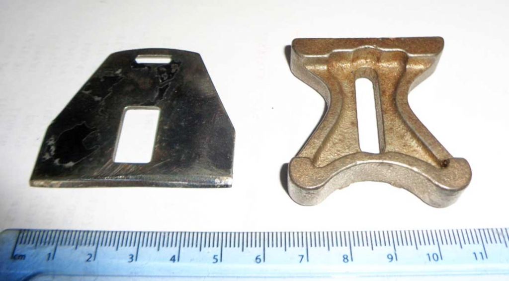
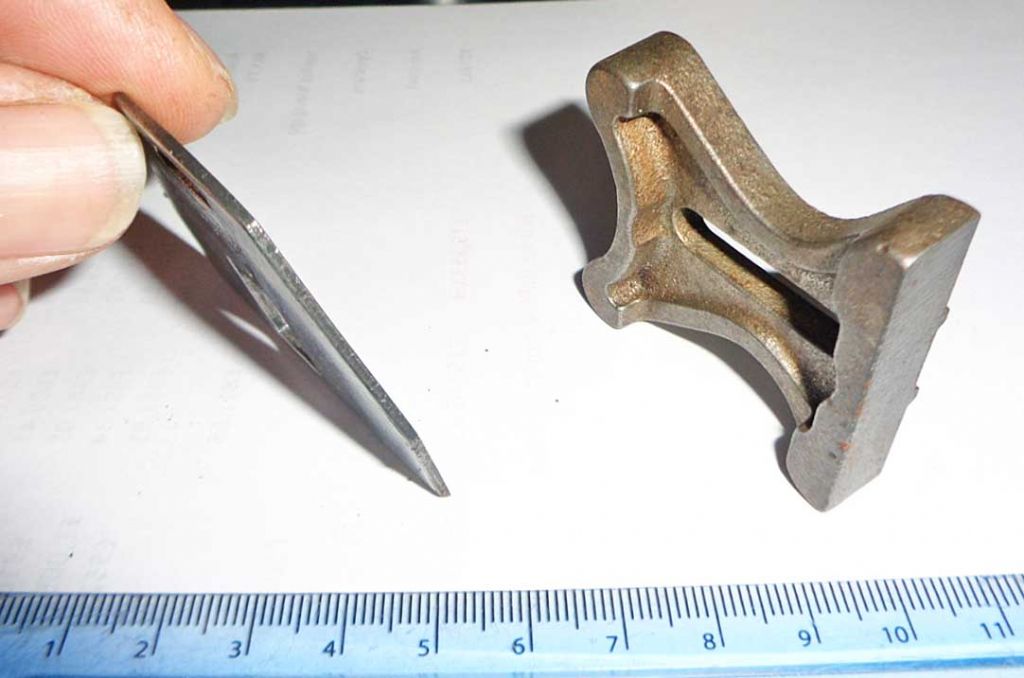
                                  Here is an original hard to find cast iron plane fence and the 3D print taken from its measurements:

                                  parts 1.jpg

                                  parts 3.jpg

                                  071fence 1.jpg

                                  Dimensions were all good within acceptable limits.

                                  Cheers, Martin

                                  #443809
                                  Bazyle
                                  Participant
                                    @bazyle

                                    Inspired by SOD's list of steps making it look easy and another thread on Hobbymat change wheels I have drawn up a small gear with the hope of getting it printed at work while people are still feeling the helpful Christmas spirit.
                                    However I'm wondering about the strength of teeth and whether there is an easy way of making the outer 3mm solid while reducing infill.
                                    Or would it be better to just thin the body to 3mm but grow out to 10mm at teeth and boss and do it all at 100%. I might do one like that as an exercise in Freecad anyway.

                                    #443818
                                    not done it yet
                                    Participant
                                      @notdoneityet

                                      However I'm wondering about the strength of teeth

                                      The right choice of filament should allay any strength fears? Carbon loaded? Perhaps reinforcing, afterwards, with dowels in printed holes would provide extra rigidity? I’m thinking of getting a printer shortly, but have to wait for the too-popular Sovol to become available again…. and looking forward to IanT’s reports which hopefully will come along shortly.

                                      #443840
                                      SillyOldDuffer
                                      Moderator
                                        @sillyoldduffer
                                        Posted by Bazyle on 29/12/2019 21:54:56:

                                        Inspired by SOD's list of steps making it look easy and another thread on Hobbymat change wheels I have drawn up a small gear with the hope of getting it printed at work while people are still feeling the helpful Christmas spirit.
                                        However I'm wondering about the strength of teeth and whether there is an easy way of making the outer 3mm solid while reducing infill.
                                        Or would it be better to just thin the body to 3mm but grow out to 10mm at teeth and boss and do it all at 100%. I might do one like that as an exercise in Freecad anyway.

                                        Whilst I'm a million miles away from knowing the answer, 3D has many possibilities. As NDIY says, some plastics are stronger/harder/ less brittle than others. That might be 'good enough'. Also possible to use the printer to make a mould, opening the door to casting iron, brass or Mazak.

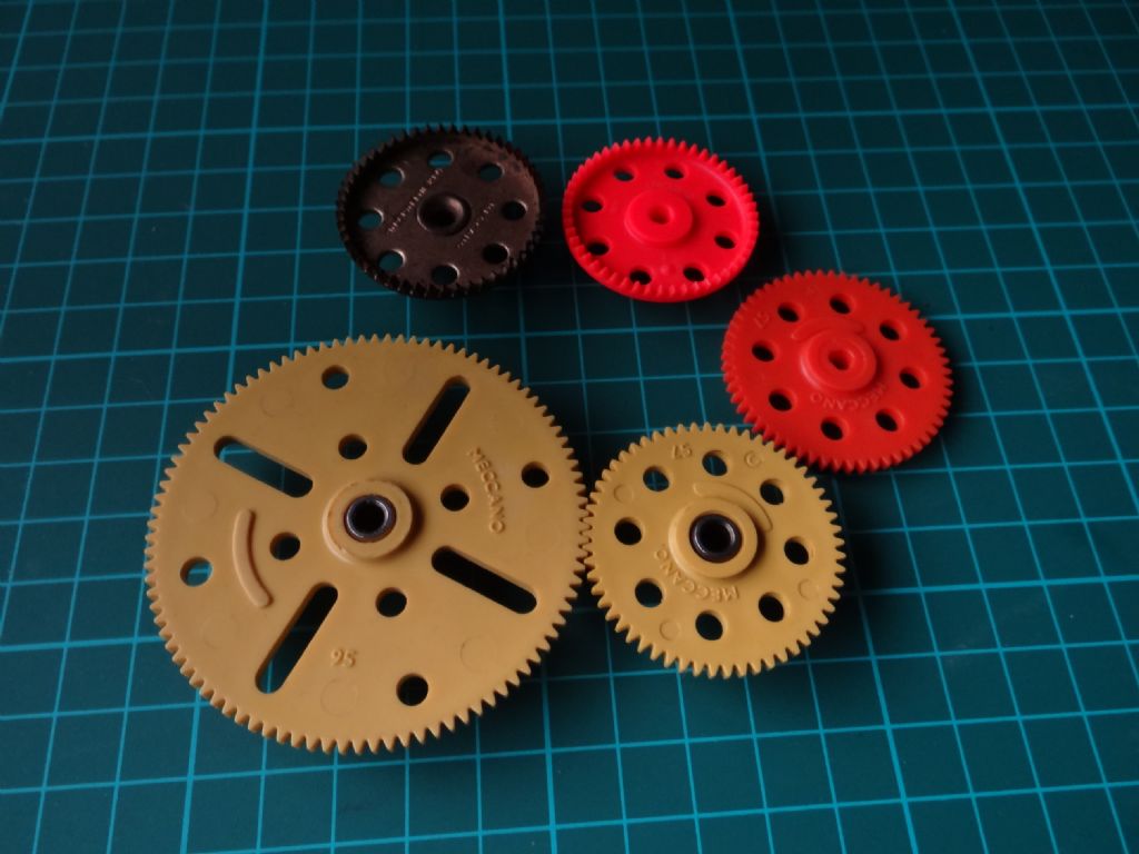
                                        Very straightforward to put holes or add rims & other extra thickness on the printed gear by design. Looking at Meccano gears, they've not changed much. Note the slightly beefed up plastic centres compared with the riveted brass boss, otherwise Meccano plastic gears are almost identical to Meccano metal gears:

                                        dsc06195.jpg

                                        (The orange gears are modern French Meccano; instead of a brass boss and set-screw, they slide on to triangular oblate rods rather than round axles. Interesting example of value engineering: rolling triangular rod must be much cheaper than making gears fitted with brass bosses.)

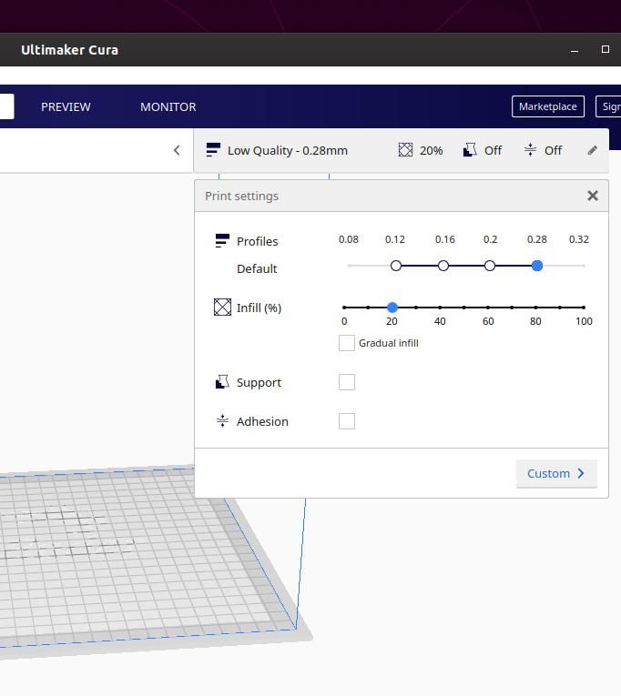
                                        In addition to adding material to weak areas during design, the Slicer may also allow control over what the printer considers 'solid plastic'. This screenshot shows Cura's settings:

                                        curasettings.jpg

                                        One of the print settings controls 'Infill', shown set to 20%, which means the object will be printed quickly but light and weak compared with a 100% setting. Not clear to me exactly how the software identifies 'infill', looks to me as if outer edges and thin structures are always 100% solid.

                                        Meanwhile, I successfully printed my honeycomb object, as Pete said I'd made the hexagon walls too thin for the printer.

                                        dsc06194.jpg

                                        Encouragingly, the print with honeycomb is the same outer size and shape as the failed print, showing that my printer is precise (repeatable) within about 0.1 mm.

                                        I'll try printing a Meccano compatible gear later: be interesting to see how it fares in a metal gear train. Or not…

                                        Dave


                                        Edited By SillyOldDuffer on 30/12/2019 09:56:42

                                        #443842
                                        Michael Gilligan
                                        Participant
                                          @michaelgilligan61133

                                          Posted by SillyOldDuffer on 30/12/2019 09:56:03:

                                          […]

                                          I'll try printing a Meccano compatible gear later: be interesting to see how it fares in a metal gear train. Or not…

                                          Dave.

                                          .

                                          I’m keen to see how that goes, Dave

                                          [ being the general sort of mechanism scale in which I am interested ]

                                          I’m almost certain that the Meccano gears are injection moulding, which of course can be more homogeneous than something built from extruded filament.

                                          MichaelG.

                                          #443843
                                          Anonymous

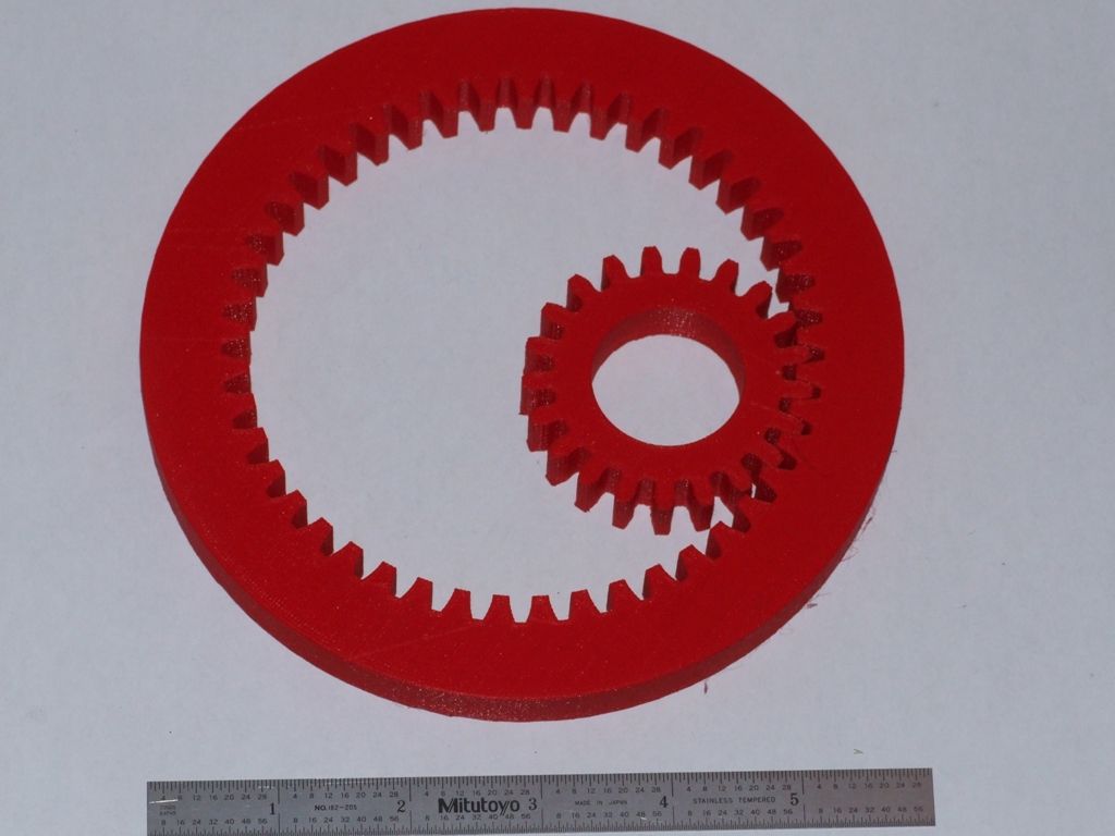
                                            No idea about tooth strength, but I'd be more worried about wear. If you can draw the gear then you can 3D print it:

                                            3d printed internal gear.jpg

                                            To get solid teeth I just increased the wall thickness to make the teeth solid, while leaving the body with infill. The gear tooth shapes as shown were accurate enough to exhibit trimming interference. Changing the pressure angle solved the interference issue.

                                            Andrew

                                            #443848
                                            Pete Rimmer
                                            Participant
                                              @peterimmer30576

                                              I also had to change the pressure angle on my Balzer gears, partly to make the different pitch gears mesh and partly because of the same type of interference.

                                              #443849
                                              Michael Gilligan
                                              Participant
                                                @michaelgilligan61133
                                                Posted by Andrew Johnston on 30/12/2019 10:17:25:

                                                […]

                                                If you can draw the gear then you can 3D print it […]

                                                .

                                                These date back to 2017 … so things may have improved:

                                                .

                                                Section of 0.75mm screw thread:

                                                printed_thread_detail.jpeg

                                                .

                                                32 DP Spur Gear:

                                                p1210621_s.jpg

                                                .

                                                At the time, I decided it was too soon for me to buy

                                                MichaelG.

                                                Edited By Michael Gilligan on 30/12/2019 10:31:05

                                                #443851
                                                Martin of Wick
                                                Participant
                                                  @martinofwick

                                                  Interesting to see how you get on with gears. Using same printer with 0.4 nozzle, anything under mod 1 is a little rough on the tooth form.

                                                  You will also need to check/adjust carefully the wall count and thickness in the cura layer view. If that shows big gaps on tooth crowns, then there will be big gaps in the print and the teeth will be weaker. You have to play with settings to minimize the effect.

                                                  Second issue I had trouble with is elephant footing – tried every which way to get rid of that and in the end had to resort to chamfering the top and bottom layers.

                                                  third issue is differential shrinkage between filled area and solid top surfaces – there would be some shrinkage across the middle of the teeth relative to top and bottom cured to some extent by chamfering the top 3 or 4 layers.

                                                  if using PLA for gears, consider post print heat treating them ( soak at constant 60-70c for a couple of hours in thermo controlled oven). You will be amazed at how tough and heat resistant the gears become, but you will have to calibrate the shrinkage amount so you can size the print correctly to allow for, typically 3-5% reduction on the XY axis. if Z is important, then you may need to allow for 1-3% expansion. Depends on material, fill, thickness etc.

                                                  Having said that, eventually I have printed perfectly acceptable gears for the Myford and Minilathe that perform very well as screwcutting and feed gears. course they wont last as long as metal, but the ones I substituted on the minilathe driven off the metal tumbler pinion are showing no signs of distress after 9 months use and if I do break one I can just go print another!

                                                  Expect to print gears quite slowly with high fill and as many walls as you can manage to get a good tooth fill with a 50t MOD1 10mm gear taking about 2 to 3 hours to complete on the bed.

                                                  When using high fills and big gears, warping becomes an issue, so higher filament and bed temps needed which of course makes elephant footing worse…. and so it goes.


                                                  Edited By Martin of Wick on 30/12/2019 11:02:37

                                                  #443855
                                                  Steve F
                                                  Participant
                                                    @stevef

                                                    Hello

                                                    The rectangle with the honeycomb has failed because it's a solid. The honeycomb is drawn and will have 2 permeter walls and an infill between them. Every hole will have a perimeter and the slicer will be quite busy with all those

                                                    If you just draw a solid rectangle and tell the slicer you want a 0.8mm wall/perimeter and what infill pattern you want this would give you what you wanted. The creality slicer doesnt do honeycomb pattern only a straight line. Cura does a large list of infill patterns but no honeycombe. This is probably because of the extra movements needed that will reduce the speed. Most of the infill patterns (there are 13) use a combination of straight lines.

                                                    regards

                                                    Steve

                                                    #443858
                                                    Neil Wyatt
                                                    Moderator
                                                      @neilwyatt

                                                      You lot ought to read my book

                                                      Overall size accuracy is generally good because its laid down bit by bit unless you get serious shrinkage or warping every bit stays where it's put and accuracy derives from the drive mechanisms which are lightly loaded and should be low backlash.

                                                      One issue is the 'ribbed' texture which means overall size as we measure it is over the outside of the ridges. If you make tow bits to fit together, these mesh together which can mean a 'perfect' fit ends up loose.

                                                      There are settings that you can use to compensate automatically for elephant's foot, the oversize of internal and external dimensions. It is worth printing simple test objects over and again to iteratively getting these settings right.

                                                      It's possible to adjust settings for thin walls, default is generally not to print anything with less than two passes (e.g 0.4 x 2 = 0.8mm with a standard nozzle). Easy to enable single thickness walls and some slicers will attempt thinner walls by reducing the amount of extrusion, but don't expect miracles.

                                                      The raft is good if you have a delicate object that is liable to break free during printing OR you want to avoid 'elephant's foot' so it's a good idea for gears.

                                                      The brim (like the brim of a hat) is excellent for adhesion and stopping distortion of corners, but has to be cut off, so not ideal for gears.

                                                      The skirt is the useful default if you are confident of bed adhesion, it gives the best finish on the underside.

                                                      Expect all sorts of entertainment when it comes to supports, Cura now has many different types and all I can suggest is playing with these.

                                                      There are also lots of fun settings like alternate extra walls which helps bind the walls to the fill and lots of fill settings.

                                                      One I like in Cura is 'fuzzy skin' which adds a random offset that gives a deeper but more attractive texture and an improved feel to objects. No good if you want a smooth or mating surface. I think one advance we can expect will be to assign different textures to different faces of an object.

                                                      Neil

                                                    Viewing 25 posts - 1 through 25 (of 116 total)
                                                    • Please log in to reply to this topic. Registering is free and easy using the links on the menu at the top of this page.

                                                    Advert

                                                    Latest Replies

                                                    Viewing 25 topics - 1 through 25 (of 25 total)
                                                    Viewing 25 topics - 1 through 25 (of 25 total)

                                                    View full reply list.

                                                    Advert

                                                    Newsletter Sign-up