Designing and building a Morgan style parallel arm 3D printer

Advert

Designing and building a Morgan style parallel arm 3D printer

Home Forums 3D Printers and 3D Printing Designing and building a Morgan style parallel arm 3D printer

Viewing 25 posts - 1 through 25 (of 26 total)
  • Author
    Posts
  • #334526
    Joseph Noci 1
    Participant
      @josephnoci1

      Well, the Spot Welder I posted about is working , done and just waiting to be powder coated, so thoughts turn to the next project…

      Of which there are two – still -planning the small (300mm BC) high speed CNC lathe, but that is a longer term project – The second is a 3D printer.

      I have absolutely NO use at all for a 3D printer – have never needed one even with all the projects I have posted on, UAV's included, let alone making tooth-brush holders..

      But the idea of perhaps an innovative design, based on the parallel arm SCARA MORGAN style mechanics intrigues me. So far I have worked out the reverse and forward Kinematics and from that created a basic mechanical construct. It intrigues sufficiently such that I am now hooked…

      Isn't this fun to watch…

      **LINK**

      Anyway, in my research things have, as usual with all my darn projects, grown somewhat – I found some brilliant Clearpath servo motors from a USA company called TEKNIC – a little pricey, but hugely better than a stepper and driver module. Procured 2 and they are oh so Nice..

      **LINK**

      This is a NEMA23, almost 2.2 times more powerful the equiv size stepper, closed loop , DEAD QUIET! – they just whisper at any speed, and you just give step and direction. Easily retrofitted to any CNC table or 3D printer as well.

      And as is usual, a little knowledge is dangerous – the more I research this whole realm, the more I find how little I know. The big issue with my chosen route is that all the open-source software is not really aimed at my intended style of machine – there are some sources, Morgan, Smoothie, Martin, etc, but all seems to be a big hack, with no clear direction, so its going to require a lot of reverse engineering is seems.

      Also, the CAD/CAM software seems to be a quagmire of mush…Fusion 360 seems good on the surface, but the South African Autodesk agents tell me that the 'free' Fusion 360'd days are numbered, and that there may be a rather blackmailious move to 'request' fees for all current free registrations by the 3rd quarter next year….

      RS offering DesignSpark Mechanical seems neat, but lacks CAM, so have to use CAMBAM ( can it slice??) or some or other Slicer, which I no doubt will have issues with, since my printer is polar and not cartesian..

      I know that asking on these forums what software to use is like sticking your neck in the guillotine , but nevertheless…

      There seem to be quite a few people doing some 'real' printing, so what do you use for CAD and what for CAM? Is Designspark Mech worth the effort?

      Is Fusion 360 worth the potential risk? Is it a 3D modelling software or parametric? Can't really get the basic info from the convoluted Autodesk site…

      Maybe I will also just do an expensive, fancy pencil balancer…

      Joe

      Advert
      #31554
      Joseph Noci 1
      Participant
        @josephnoci1
        #334537
        Ian P
        Participant
          @ianp

          The pencil balancing demo is very impressive. Its not that long ago (well it might be over 20 years) I saw an equally impressive (for the time) demonstration on a university recruitment stand at an engineering design exhibition. They managed the trick of balancing a briefcase on one of its short edges.

          Other than the challenge I don't see any reason to use the parallelogram type mechanism. For the printer you still need the Z axis anyway. Regarding the 3D printer, (that I too don't need) but I would be very tempted to build a SLA type using a DLP chip out of a digital projector which when only projecting on to a small build area, rather than a screen viewed by a room full of people, has extremely high resolution.

          "Fusion 360, Is it a 3D modelling software or parametric? Can't really get the basic info from the convoluted Autodesk site…"

          But at least you can try it for free.

          Ian P

          #334577
          Joseph Noci 1
          Participant
            @josephnoci1

            Ian, I agree completely. I have built two CNC routers, one a 900mmx800mm work area, the other an A4 size table for engraving PCB's – you may have seen my photos. So a 3D printer along those lines would be much simpler and the way to go if the aim was to have and use a printer…

            I like the SLA concept very much, but it is very difficult to get the consumables here. The parallelogram style is a good exercise for the mind in mathematics, mechanics and software..

            Regarding the CAD packages – the problem as countless have mentioned, is the investment in tedious time and the not insubstantial learning curve on these systems – only to discover after weeks of time spent that it does not do things the way you thought, or has limitations that screw you, etc…I was hoping for some real users to give objective words on why they use what they use.

            Joe

            #334580
            John Haine
            Participant
              @johnhaine32865

              **LINK**

              Not very relevant but fun! They also have videos of drones juggling.

              #334594
              Swarf Maker
              Participant
                @swarfmaker85383

                Joe, you have a private message in your inbox.

                #334618
                Joseph Noci 1
                Participant
                  @josephnoci1

                  Have responded – Thanks Swarf Maker!

                  Joe

                  #334620
                  Muzzer
                  Participant
                    @muzzer
                    Posted by Joseph Noci 1 on 31/12/2017 06:25:29:

                    Regarding the CAD packages – the problem as countless have mentioned, is the investment in tedious time and the not insubstantial learning curve on these systems – only to discover after weeks of time spent that it does not do things the way you thought, or has limitations that screw you, etc…I was hoping for some real users to give objective words on why they use what they use.

                    Joe

                    Search this forum for previous discussions on CAD and CAM – this comes up regularly and the responses are pretty consistent. Having used most of the mid-range applications myself in a professional environment (Solidworks, Solid Edge, Inventor etc), I can tell you that Fusion 360 will do everything you need in CAD. The key difference is that it will also do everything you need in CAM including multi-axis toolpaths – and it's proper professional stuff (the CAM element is actually HSMWorks, which Autodesk acquired a few years back).

                    There are several other options available if you don't mind a rather more limited application (CAD-only), such as TurboCAD, Designspark Mechanical (aka Spaceclaim) and Onshape. Although users seem happy with them, it's not obvious why you'd choose to invest your time on them when you can get state of the art professional CAM (and 2D drawings, simulation, sheet metal, surface modelling, rendering etc) included for free, along with a massive community and active (free) professional support. The volume of tutorials, videos, forums etc that are available for Fusion is simply unrivalled, so you should be able to find the method that works best for you.

                    The Clearpath systems look pretty good but also fairly pricey. Alternatives might include the DMM Technology servos (true closed loop servos at the cost of a stepper system) or Leadshine (for example) closed loop steppers (many advantages over simple, open loop steppers. The Leadshine "Integrated Easy Servo" even has the drive integrated into the motor (rather like the Clearpath) and you can now get cheap clones from AliExpress.

                    The "free Fusion 360 is ending" chestnut will come up from time to time. I've asked (again) for an official restatement of their position and hope to get a reply in the next few days. You can never say never but I'm pretty certain we're not about to get a nasty surprise.

                    Murray

                    #334638
                    Joseph Noci 1
                    Participant
                      @josephnoci1

                      Thanks Murray.

                      I have done a fair bit of searching on the CAD subject on the MEW forums Murray – if only because I become irritated myself when different folk keep asking the same questions on any subject, again and again, showing they did not spend time digging! I have spent a few weeks now, digging here, and googling myself silly. The problem distils to one of 'everyone is an expert' until details start to be discussed..

                      I have downloaded Fusion and spent only this afternoon playing – completely lost I must admit, but I will play on. I am a little averse to the fact that what I do does not remain on my computer? Seems to be stored in Autodesk's vault somewhere? Is there a way to save the project locally? Cant seem to find any reference to that, but then maybe I need to get with the program and cease being an old Fart…

                      I have looked at all those Servo/Stepper type systems you mention, and a few others. What is really nice with the Clearpath is the PC tool you connect to the servo via USB, and then tune its PID control loops automatically – You can adjust torque, speed, etc, and you can auto-tune the loops so that the accelerations are as fast as you want, for the inertial masses involved, and with the least vibration, bounce and spring. And it is pretty intuitive, no control theory needed!

                      Thanks..

                      Joe

                      #334640
                      Swarf Maker
                      Participant
                        @swarfmaker85383

                        Joe,

                        Any model that you generate is also stored on your local computer and is available for when you are off-line. the baseline for storage is 'project' and within that you need to construct a library structure (file folders) to keep track of where you keep related things.You can also export copies of any/all of your models as either fusion *.F3d, *.igs, *.iges, *.stp, *.step, *.sat or *.smt to wherever on your own computer you wish to store them.

                        Think of the cloud as your backup.

                        You have some further PM's to read.

                        #334670
                        Muzzer
                        Participant
                          @muzzer

                          If you go into the preferences menu (click your name at top RHS of screen and select "preferences&quot, you can change the "offline cache time period (days)" to the maximum of 360 days. So it will work locally for up to that duration in the absence of an internet connection to its server. As SM says, it's best to think of the cloud as your backup rather than some sinister plot to acquire and flog off your IP.

                          If you go into the "data panel" (by clicking on the funny square icon at the very top left of the screen), you can see all of your projects as they are held on the server. You can right click on the ones you want to store and work on locally ("add to offline cache&quot and they will be available to work on when Fusion can't see the server.

                          Loads of Youtube videos to watch that will help you get up to speed – nothing like watching someone to learn from them! Check out Lars Christensen, NYC CNC, Autodesk Fusion 360 etc.

                          Murray

                          #334745
                          Joseph Noci 1
                          Participant
                            @josephnoci1

                            Ian, Murray, Fred, and all those helping me along…

                            Thanks for the assistance – I think I may have passed Fusion-360 by rather unfairly were it not for you chaps encouraging me!

                            I have spent most of the last day of last year and the first of this playing, doing tutorials, and watching videos, and suddenly, it would appear, the click occurred deep in the brain – well, enough of a click to make me feel this is the way to go!

                            Did a simple arm, with some holes, one blind, did the G-Code for it, simulated it on Fusion CAm and on my trusted NCPlot CNC simulator, and then and ran it on my router, cutting free space, and everything worked!

                            Thanks very much to you chaps! Much appreciated.

                            Going to dump Rhino…

                            Certainly these forums are worthy!

                            regards

                            Joe

                            first 360 in ncplot.jpg

                            first 360 trial.jpg

                            #334872
                            Neil Wyatt
                            Moderator
                              @neilwyatt

                              Might interest people to see the original RepRap Morgan.

                              #334874
                              Neil Wyatt
                              Moderator
                                @neilwyatt
                                Posted by Muzzer on 31/12/2017 13:53:46:

                                The "free Fusion 360 is ending" chestnut will come up from time to time. I've asked (again) for an official restatement of their position and hope to get a reply in the next few days. You can never say never but I'm pretty certain we're not about to get a nasty surprise.

                                Murray

                                Having been caught recently by a very useful program ceasing development and moving to an annual licence (only a very cheap one), and looking at what has happened to some of Autodesk's 3D print utilities I suspect that Fusion 3D won't force people across to a pay for model. Instead It will either freeze, disappear as a standalone and be incorporated into a costly 'suite'* or more likely continue as a 'student hobbyist' product but with ongoing 'feature rot' that moves pro users over to the full version.

                                Neil

                                *Take a look at what's happened to their 2D image to 3D model software.

                                #337391
                                Nick Hulme
                                Participant
                                  @nickhulme30114
                                  Posted by Neil Wyatt on 02/01/2018 09:56:15:

                                  what has happened to some of Autodesk's 3D print utilities I suspect that Fusion 3D won't force people across to a pay for model. Instead It will either freeze, disappear as a standalone and be incorporated into a costly 'suite'*

                                  Not forgetting the way Autodesk is also hoovering up small companies to take free utilities off the market and either kill the products or incorporate them into paid products.

                                  I genuinely believe Autodesk has a policy of killing free and open source software in order to delay the development of free or open source CAD/CAM 😀

                                  #337493
                                  Joseph Noci 1
                                  Participant
                                    @josephnoci1

                                    Well, we will have to see what develops with Fusion – in the meantime I have progressed in my use thereof and am actually quite impressed with it. I am quite comfortable in transferring the 3D image in my head onto the screen with Fusion- far easier than CATIA and Solidworks.

                                    And so the Morgan par-arm printer is progressing – I have modelled the arms, pivots and bearings, and managed to make the arms and sockets. Pivots are next..

                                    The arms will be driven by those amazing ClearPath AC- Servo-motors that behave like steppers but are fast, closed loop and very powerful. Both arms will be driven by a 15mm diameter steel gear on each motor, driving a 130mm diameter PET gear on the arm ( actually an ALIGN large RC helicopter rotor drive gear). tests so far show no discernible backlash..time will tell. The Z axis ( still a lonnggg way of in my mind..) will use a normal stepper.

                                    Each arm pivot uses 3 ball thrust bearings, as does the tool pivot. The main arm pivot uses 4 pre-load Ball bearings.

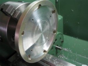
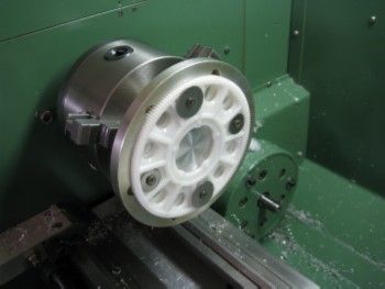
                                    The jig made to hold the PET 130mm diameter gear to machine the center hub concentric.

                                    The gear outer fits snugly in the jig.

                                    morgan gear machining jig-1842.jpg

                                    Machining the gear hub:

                                    morgan drive gear machining jig-1839.jpg

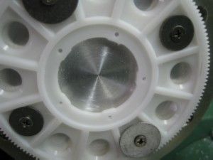
                                    The centre machined to be concentric with the outer gear circunference.

                                    morgan drive gear boss location machined-1840.jpg

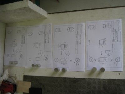
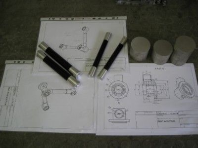
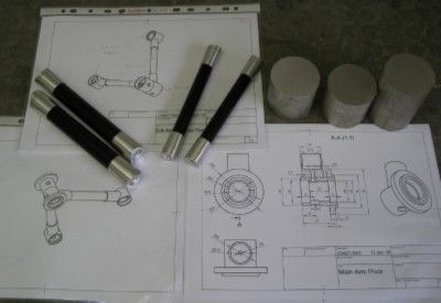
                                    The arm pivot sockets all drawn up and raw material ready to start..

                                    morgan arm pivot sockets-1.jpg

                                    Machining the pivot sockets:

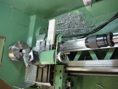
                                    NEVER let it be said that my machines never see swarf!

                                    machining morgan arm pivot sockets.jpg

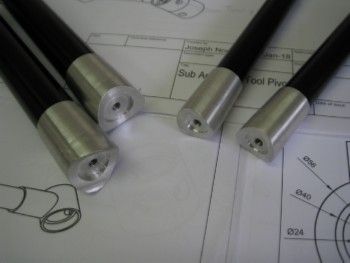
                                    The arms fitted with Pivot sockets:

                                    morgan arms and pivot sockets.jpg

                                    End of the sockets will fit onto the Pivots which house the thrust bearings – more to follow as we slowly progress..

                                    morgan arm pivot socket ends.jpg

                                    Joe

                                    #337758
                                    John McNamara
                                    Participant
                                      @johnmcnamara74883

                                      Hi Joseph

                                      Like many others I am slowly becoming proficient with Fusion 360, having spent many years using AutoCAD as a two and 3D tool. So far I can work a lot faster using Acad when creating drawings. While the parametric design features provided by Fusion can be used to control dimensions and assist in accuracy the editor is not as efficient, (for me anyway) moving between drawings in fusion can also be a slow process, a simple save taking many seconds as the program updates the server and the local files. If you keep each component in a separate file as I do the design process involves constantly moving between files. Fusion does allow you to have several files open at one time. Acad allows you to edit a component in an assembly drawing in place a very useful feature. I have not found a way to do this in fusion.

                                      My interest in fusion is focussed on the CAM features here it clearly excels. It can also do mechanism simulation, finite element analysis, sheet metal, Etc. It also handles free form 3D design very well, things that Acad cannot do or do well.

                                      The good news is that Fusion can "upload" many 3D CAD drawing formats including DWG and DXF files. Therefore I can have the best of both worlds. The imported drawing can be edited within fusion if need be.

                                      For now I will continue working on improving my modelling skills using Fusion directly, while continuing to use Acad for larger design projects that are already created and import them into Fusion. Moving to fusion does not mean you have to abandon the program you are using now. Maybe I will move entirely, maybe not. The best of both worlds.

                                      Oh! I really admire your work.

                                      Regards
                                      John

                                      #337767
                                      Muzzer
                                      Participant
                                        @muzzer

                                        John – I believe that you are recommended to create your components within one assembly file, rather than create them separately and bring them together. That's what I now do and it seems to make sense. You can indeed edit individual components within an assembly without having to come out of each. And of course, you can have several 3D models (assemblies) and 2D drawings (and CAM etc) all open in their own "tabs". Like most mid-range CAD, you can create and modify new components in situ.

                                        When you create a new component from another within an assembly, you get all of the benefits of linked components, so they update correctly when you change something (as do the 2D drawings, CAM etc too). Nothing particularly new there, as the other products do much the same – they have to in order to be competitive.

                                        Hopefully you will figure out how to get Fusion to work your way. One of the key confusions I found was the difference between bodies and components – certainly, within an assembly, you want to be certain to be creating new components (not new bodies) or things can get smelly!

                                        Murray

                                        #337771
                                        John McNamara
                                        Participant
                                          @johnmcnamara74883

                                          Thanks Murray

                                          I get that one file is preferred by Fusion 360, I worry about a complex mechanism sitting in one file. When I started with Acad I did it that way, for me the problem was the overhead was so great that the program slowed to a crawl My current computer is an I7 with all the extras so no problem there. There is also the systemic risk of a huge file being corrupted, You have to backup every hour.

                                          I like to design machines….. gee now I have some time I might even start building one!, I want to build another CNC router and a CNC milling machine based on Epoxy castings. Machines contain a lot of components. in the 100's is normal. I like to tuck them away in a library directory for reuse. A huge time saver. for Acad I copy any library components I need into the project working directory then link them into the drawing, that way if i change a component in the project working directory it will be updated into the project files that use it. from time to time I copy new components back to the library directory for reuse.

                                          Most of the Fusion projects I see on YouTube are simple components or maybe something like a push bike etc.
                                          I would really like to see how it handles a complex mechanism in one file. I would also like to see in place editing of linked files implemented the same way Acad does it.

                                          Yes in Fusion Components are the way to go using bodies for cutting, well that's how I see it.

                                          Regards
                                          John

                                          #337778
                                          John McNamara
                                          Participant
                                            @johnmcnamara74883

                                            Hii

                                            I did a little google searching on creating large models within fusion, The following document is worth reading, its a couple of years old but the basics have not changed that much.

                                            It is titled:
                                            "Fusion 360 Large Model Management for productivity and performance"

                                            **LINK**

                                            Regards
                                            John

                                            #337804
                                            Muzzer
                                            Participant
                                              @muzzer

                                              The auto recover save time is set to 5 mins in my preferences (possibly the default value, I forget) and I also save each time I make a significant change. If you open the data panel and click on the bottom right of each file where it shows the current version of that file, it will show you every version you have saved, the time and date and any comment you made when saving. It's then possible to go back to that version and either save it for some other use or promote it to the latest version. That's a lot more useful than a simple "undo" operation which generally can only take you back to the beginning of the session at best or possibly up to the last save.

                                              If you "insert component into current design", any subsequent updates to that component will automatically carry through – unless you choose to break the link. I believe that's normal in most CAD.

                                              To edit a linked component within an assembly (indicated with a chain symbol), you just right click on it in the component list and select open. If it's not linked, you simply activate it (select the component and either click the radio button at the right of the name or right click and select "activate" ). You are then working on just that component and the history line shows operations just for that component. If you want to hide the other (shadowed) components whilst editing that component, you right click and select "isolate". That's not a lot different to how the other programs do it, IIRC.

                                              For machine parts, I often download standard 3D models from Traceparts, which is a repository of commercial files, created by professional CAD jockeys to support the use of their company's products. The range of models there is pretty amazing and usually well modelled. Often they aren't exactly the components I want but it's simpler to modify them than start from scratch. In contrast, Grabcad seems to be mostly amateur stuff, often (but not always) littered with errors or simply not capable of functioning when you look closely. Some stuff is pretty good but it's up to you to check carefully.

                                              I'm not exactly sure where the threshold to "complex" is. Most of the products we see (Fusion, Solidworks, Solid Edge, Alibre etc) are described as "mid range" and good for products such as gearboxes, engines, ECUs etc rather than complete vehicles (as an example). For the "top end" stuff, you move to products like Catia (from SW), NX (from Solid Edge) etc which can handle entire vehicles, space craft and the like but the likes of us will never need to get involved in stuff like that and probably wouldn't have the time on this planet to use them meaningfully. Fusion is aimed at the mid range market and when development is complete, it should be able to do at least what the competition does.

                                              Murray

                                              #339480
                                              Joseph Noci 1
                                              Participant
                                                @josephnoci1

                                                I have made 'some' progress on the arms and pivots for this 'printer'…

                                                I will create a new post next time round to try decontaminate the rest of the 'progress'..

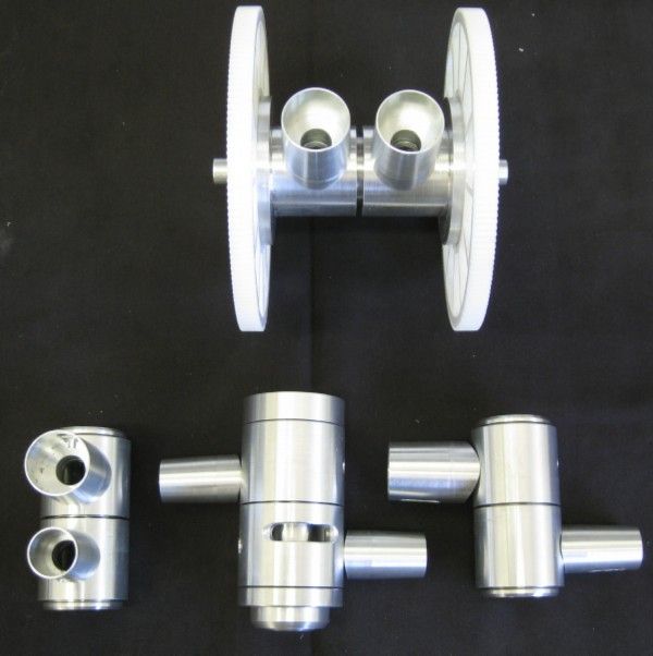
                                                I made all the arms, arm sockets, and the various pivots – the main drive pivot, the two elbow pivots, and the tool holder pivot. The main drive pivot uses 4 preloaded ball bearings, and the elbow and tool pivots use 30mm OD and 35mm OD thrust bearing respectively.

                                                All are preloaded to ensure the assembly is stiff to prevent any tool head sag, co-planarity of motion is also important for obvious reasons.

                                                And LOTS of swarf was made..

                                                The arms and sockets – not yet loctited..and Raw stock for pivots, and drawings from Fusion 360.

                                                arms-dwgs-1874.jpg

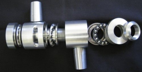
                                                The Tool Pivot, exploded view..Has a central 18mm hole through which the extruder head passes the filament.

                                                The idea is to have the hot end below the pivot, and the nozzle/hot end be inductively heated – working of a prototype of that concept and has great promise..

                                                tool pivot exploded-1891.jpg

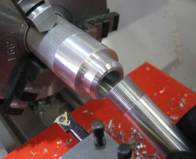
                                                The central tube in the Tool Pivot – threaded using my ELS on the 14D with multifix retracting tool holders..

                                                threads using my els1888.jpg

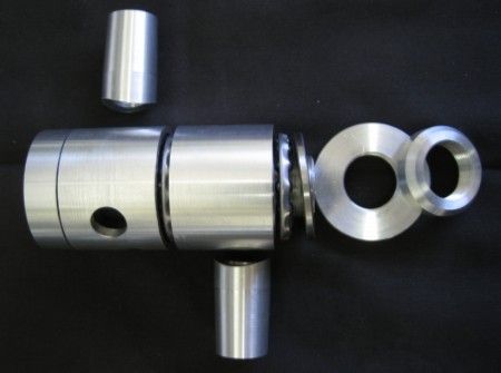
                                                Part exploded view of one of the two Elbow Pivots. The short tubes, as above, are the sockets into which the tubing arms fit. These socket will be TIG welded onto the pivots and the tube arms inserted , in a jig to ensure length and co-planarity are met, and loctite applied

                                                elbow pivot exploded-1892.jpg

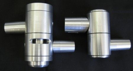
                                                Tool and Elbow Pivots part assembled, not yet welded..

                                                tool - elbow pivots-1894.jpg

                                                The drive Pivot is uppermost in the image below – fitted with the main reduction drive gears – 140mm diameter gears, from an Align 700 RC helicopter main rotor drive.

                                                The Left and Right Elbow Pivots are seen, with the Tool Pivot between.

                                                tool-elbow-drive pivots.jpg


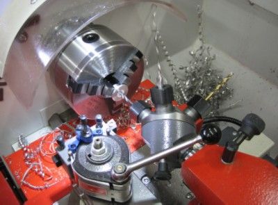
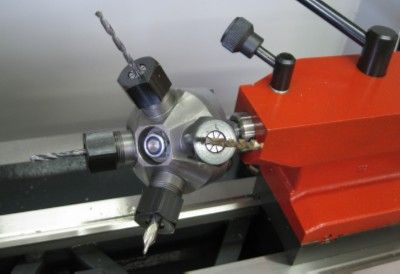
                                                First time I used the new lathe's Tailstock Turret – had a handful of threaded bosses to make, and it came in very handy!

                                                tstock turret in use-1883.jpg

                                                It uses ESX16 collets…

                                                tstk turrest esx16 collets1886.jpg


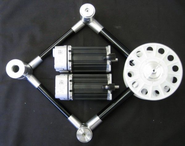
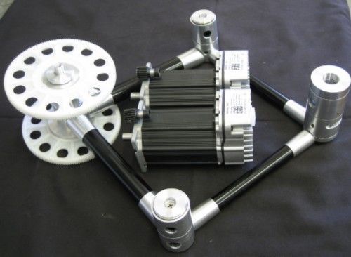
                                                Mockup of assembly with the drive motors – TEKNIC AC Closed loop Servo motors.

                                                The mating drive gear that fits to the motor shaft is visible atop the motor casing at it's shaft end.

                                                motor assy top.jpg

                                                More assembly mockups:

                                                motor - assy lo.jpg

                                                Arms closed

                                                arms closed mockup.jpg

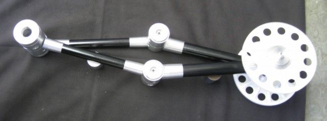
                                                Arms open

                                                arms open mockup.jpg


                                                Then start on the support frame work to which the drive pivot mounts, as well as the two drive motors.

                                                I am also working on an inductively heated hot-end as well as inductive heating of the print hot-plate. The Hot end prototype is very promising – using a heat treated/hardened silver steel nozzle with slightly extended rear in a tube form, around which a 20 turn, single layer coil, 15mm long fits. 13.54Mhz of RF is applied and 40 watts heats the nozzle to 400degrees in 18seconds, 200degrees in 7 seconds. I am using similar concepts as applied in the Metcal Soldering irons, also RF inductive tip heating, and measure SWR to the coil to regulate temperature – the SWR changes as the temperature changes, and the relationship is workable.

                                                The hotplate trial are around a 3mm flat ( hopefully) steel plate backed by a close wound recangular, flat ( 1 Wire thick) coil, with 50 watts of 135kHz applied – so far the plate heats to 70deg C in 20 seconds and to keep it there seems to require about 12 to 15 watts. Heating seems to be pretty evenly spread as the coil covers the working area quite nicely- a max area rectangle of around 350mm x 250mm, with a much larger  half circle.

                                                Joe

                                                Edited By Joseph Noci 1 on 02/02/2018 15:10:57<

                                                #339819
                                                ronald mill
                                                Participant
                                                  @ronaldmill41152

                                                  good work !!! keep it up

                                                  thanks

                                                  #340024
                                                  Zebethyal
                                                  Participant
                                                    @zebethyal

                                                    Loving your build and following it with interest – the parts you have built thus far look way more study than used in most hobby 3D printers.

                                                    I built my first 3D printer using a set of Prusa I3 parts and some shelf panels, to my own design, having first re-created all of the parts in Google Sketchup and then modelled the printer from scratch. I have since replaced several of the parts, some broke, some needed improvement, some were just additions to the design.

                                                    I have since used it to print all of the parts for my Buildlog.net 2.0 Laser Cutter, and all the parts for a 2020 Mini Kossel 3D printer, some parts again were my own designs.

                                                    To date most of my modelling for items I wanted to print, has been in Sketchup, although more recently I have started modelling my Mini Mill, and associated CNC conversion parts, in Fusion 360, as a learning exercise.

                                                    For printing, I use Repetier firmware and the associated Mac frontend, although most prints are performed from Gcode stored on an SD card, I merely use the front end for initial setup and kicking off the print.

                                                    The printer has largely sat idle for a year or more as I am currently struggling to dream up things I want to print with it – the last serious items were Nema23 end covers for the various axes of my Mini Mill CNC conversion.

                                                    #340257
                                                    Joseph Noci 1
                                                    Participant
                                                      @josephnoci1

                                                      Some further progress on this thing..

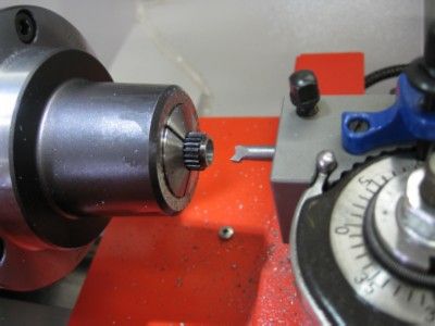
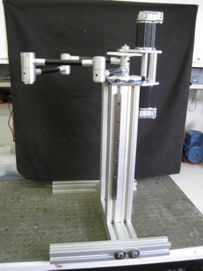
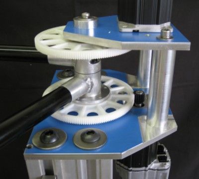
                                                      Built up the main frame and mounting plates, and fitted the arms and motor. Bored out the drive gear using, for the first time..the Bison Set-True 5C collet chuck – worked a treat!

                                                      The Z axis is still to be done, but not going to do that effort until I have got the maths and Kinematics working, and that the control software can position the arms correctly and accurately. If I fail, no time wasted on Z!

                                                      At least the arms and the whole frame is very stiff and rigid!

                                                      boring the drive gear.jpg

                                                      Side view – Z slide rail is visible.

                                                      full side v.jpg

                                                      The gear train and drive head

                                                      gear train.jpg

                                                      gears and arms.jpg

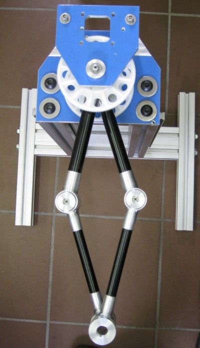
                                                      View from top, arms almost fully open

                                                      top open.jpg

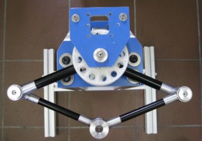
                                                      and closed a little

                                                      tope closed.jpg

                                                      A video if, and when, it swings arms..

                                                      Joe

                                                    Viewing 25 posts - 1 through 25 (of 26 total)
                                                    • Please log in to reply to this topic. Registering is free and easy using the links on the menu at the top of this page.

                                                    Advert

                                                    Latest Replies

                                                    Viewing 25 topics - 1 through 25 (of 25 total)
                                                    Viewing 25 topics - 1 through 25 (of 25 total)

                                                    View full reply list.

                                                    Advert

                                                    Newsletter Sign-up