The Workshop Progress Thread 2023
The Workshop Progress Thread 2023


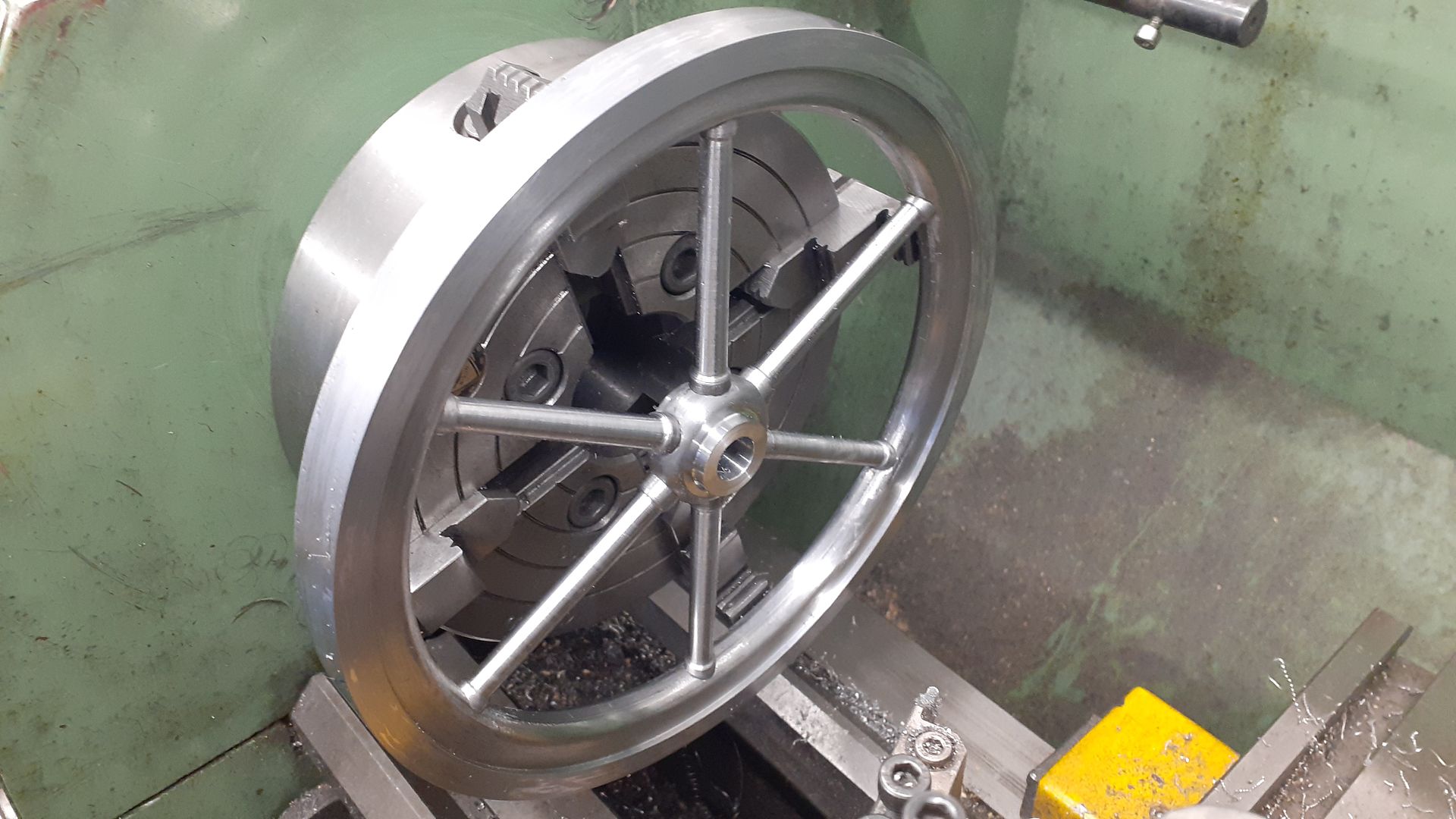
![20230214_191921[1].jpg](/wp-content/uploads/sites/4/images/member_albums/44290/920447.jpg "20230214_191921[1].jpg")


Latest Replies
-
- Topic
- Voices
- Last Post
-
-
Starrett micrometer.
Started by:
 Graeme Seed
in: Workshop Tools and Tooling
Graeme Seed
in: Workshop Tools and Tooling
- 5
-
3 July 2025 at 12:26
Graeme Seed
-
Loctite axles
Started by:
steve2250
in: General Questions
- 5
-
3 July 2025 at 12:22
parovoz
-
Bearing boxes for ball race
Started by:
Paul McDonough
in: Beginners questions
- 10
-
3 July 2025 at 11:23
Perko7
-
Comments (constructive) on the New Forum Software
1
2
…
34
35
Started by:
JasonB
in: New Forum Software questions, comments and Test Threads
- 134
-
3 July 2025 at 10:25
Emgee
-
Bentley BR2 Rotary Aero Engine
Started by:
notlobgp14
in: Miscellaneous models
- 1
-
3 July 2025 at 10:11
notlobgp14
-
Twin Engineering’s heavy mill/drill quill removal
Started by:
Martin of Wick
in: Manual machine tools
- 9
-
3 July 2025 at 09:15
Nicholas Farr
-
Grimsby & Cleethorpes MES on the BBC
Started by:
Chris Crew
in: The Tea Room
- 1
-
3 July 2025 at 08:51
Chris Crew
-
Injectors
Started by:
pansy123
in: General Questions
- 6
-
3 July 2025 at 07:05
Dave Wootton
-
Pattern Makers Vice
Started by:
Vic
in: The Tea Room
- 7
-
2 July 2025 at 21:51
KEITH BEAUMONT
-
J&S grinder – belt which way ?
Started by:
gerry madden
in: Manual machine tools
- 7
-
2 July 2025 at 21:44
not done it yet
-
Meddings MF4 Manual
Started by:
Richard Kirkman 1
in: Help and Assistance! (Offered or Wanted)
- 11
-
2 July 2025 at 21:38
Richard Kirkman 1
-
Haining vertical dairy engine boiler.
Started by:
apprentice
in: Beginners questions
- 3
-
2 July 2025 at 20:52
JasonB
-
Speed camera
1
2
Started by:
David George 1
in: The Tea Room
- 20
-
2 July 2025 at 20:01
Plasma
-
Motor won’t start
Started by:
Rowan Sylvester-Bradley
in: Beginners questions
- 9
-
2 July 2025 at 17:30
larry phelan 1
-
IME Watchmakers lathe
Started by:
Greensands
in: Manual machine tools
- 11
-
1 July 2025 at 21:41
Dave S
-
Request for a Slot to be Milled in a Shaft
Started by:
James Alford
in: Help and Assistance! (Offered or Wanted)
- 9
-
1 July 2025 at 21:03
bernard towers
-
The Stevenson Trophy – Entries Invited
Started by:
Neil Wyatt
in: Website Announcements
- 1
-
1 July 2025 at 18:44
Neil Wyatt
-
The Bradford Cup – Nominations Wanted
Started by:
Neil Wyatt
in: Website Announcements
- 1
-
1 July 2025 at 18:41
Neil Wyatt
-
FreeCAD v1.0 tutorials
1
2
3
Started by:
Michael Gilligan
in: CAD – Technical drawing & design
- 12
-
1 July 2025 at 18:31
Speedy Builder5
-
All things Beaver Mill
1
2
…
8
9
Started by:
Robert James 3
in: Manual machine tools
- 43
-
1 July 2025 at 18:22
Charles Lamont
-
Dial test indicator vs Dial indicator
Started by:
martian
in: Workshop Tools and Tooling
- 17
-
1 July 2025 at 16:59
Clive Foster
-
Help for DIY lathe build.
1
2
Started by:
moogie
in: Help and Assistance! (Offered or Wanted)
- 16
-
1 July 2025 at 15:21
David Senior
-
Firth Valve Gear
Started by:
Andy Stopford
in: Traction engines
- 9
-
1 July 2025 at 12:59
Nigel Graham 2
-
M type top slide conversion??
Started by:
jimmyjaffa
in: Beginners questions
- 7
-
1 July 2025 at 11:35
David George 1
-
Offen screw type telescopic gauge.
Started by:
Graeme Seed
in: Workshop Tools and Tooling
- 4
-
1 July 2025 at 10:41
Graeme Seed
-
Starrett micrometer.
Latest Issue

Newsletter Sign-up
Latest Replies

