Dynamic Balancing a BLDC motor rotor.

Advert

Dynamic Balancing a BLDC motor rotor.

Home Forums Work In Progress and completed items Dynamic Balancing a BLDC motor rotor.

Viewing 7 posts - 1 through 7 (of 7 total)
  • Author
    Posts
  • #561224
    Joseph Noci 1
    Participant
      @josephnoci1

      The CNC Lathe I am building has  live tooling  requiring a drive motor. I used a BLDC motor , with modifications to the motor rotor housing, to be able to fit into/onto the ATC mechanism.

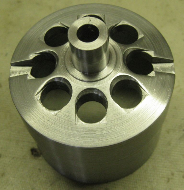
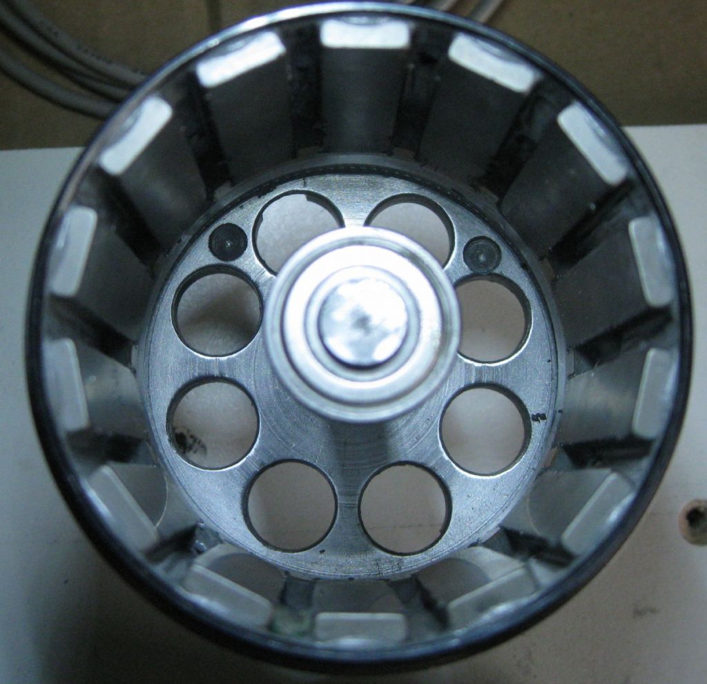
      The  motor is an 'outrunner' where the outer housing, the rotor, spins. I modified this housing to fit into a new housing which has a bearing spigot to take rotational loads in the ATC. These modification require that rotor be balanced again. Very little mass had to be removed, I guess thanks to good setup in the CNC mill during machining.

      rotor aircooling1.jpg

      The existing motor rotor bell end was removed and the rotor pressed into the new housing – photo above.

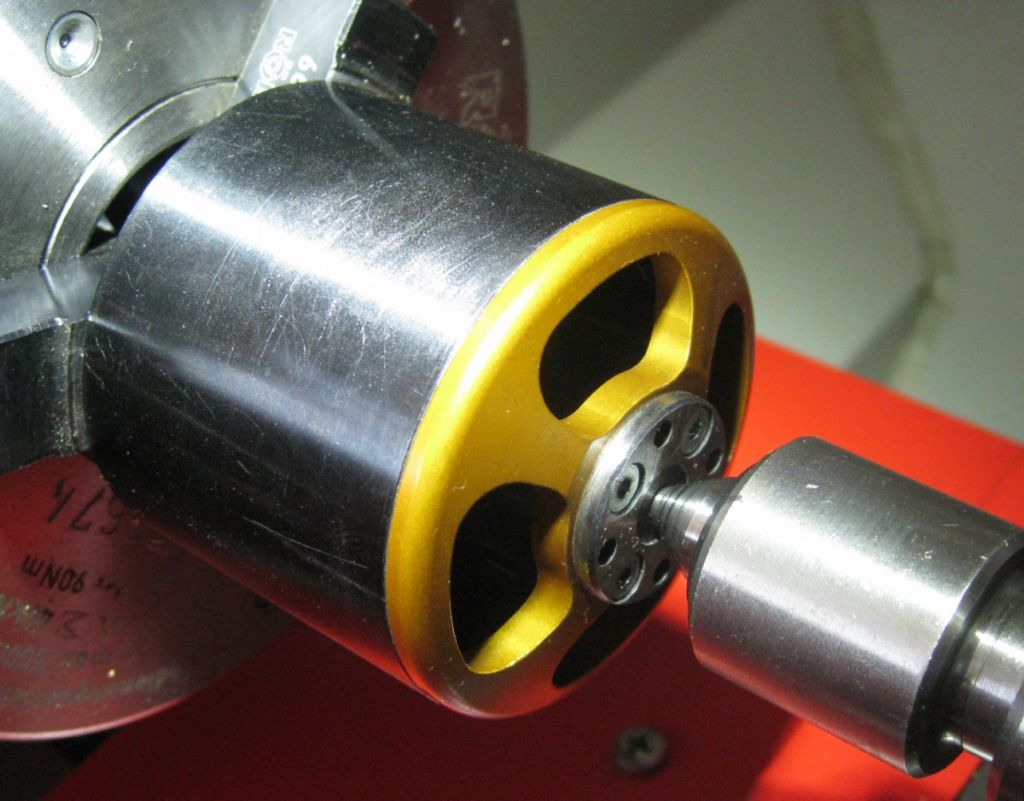
      The yellow part to be cut off/out-

      bell end to cut off.jpg

      End removed and rotor cleaned up.

      cutting out bell end.jpg

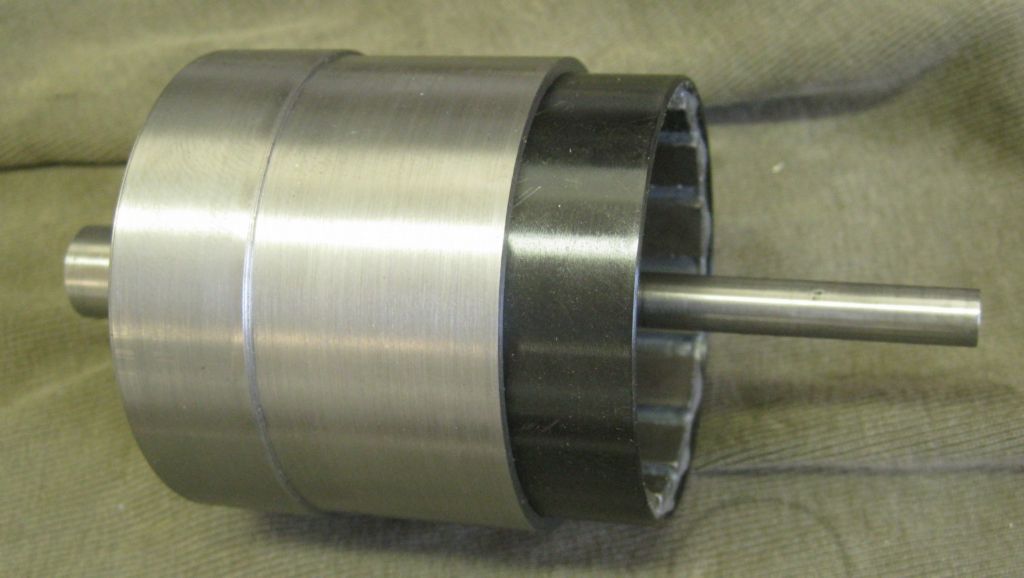
      And pressed into the new Rotor housing.

      motor magnet rotor in housing.jpg

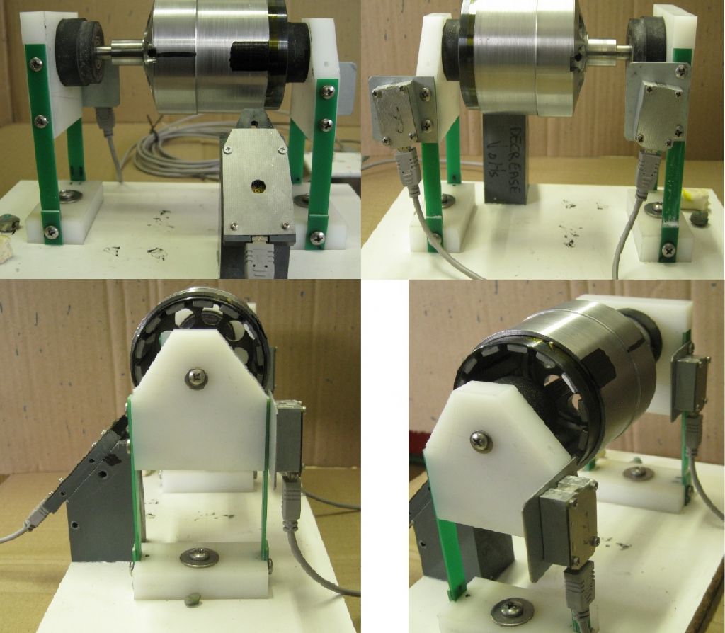
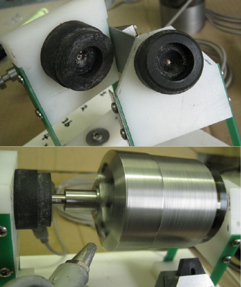
      A balance jig  allows the rotor to float easily front and back, with accelerometers ( left and right) attached in the same plane.

      Views below show;

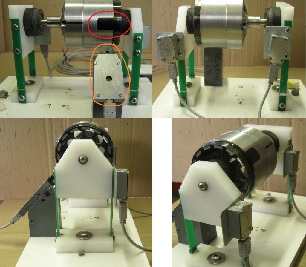
      TOP LEFT = Front View – the lower right is an optical detector detecting the start of the black line on the rotor. This measures RPM and the jig is calibrated by attaching a weight at the rotor reference position which coincides with that detection edge. The rotor is spun up and the referenced This calculates the zero deg angle for weight placement reference. The test weight is then removed.

      TOP RIGHT = Rear View, showing the two accelerometers, magnetically attached. Two accelerometers are used,  since I need to do two plane dynamic balancing.

      BOTTOM LEFT and RIGHT = side and side/rear views.

      balance jig views.jpg

      The Upper image of below shows the bearing housings on the test jig, the Lower image shows the air spout used to spin the rotor up.

      air spinning and bearing housings.jpg

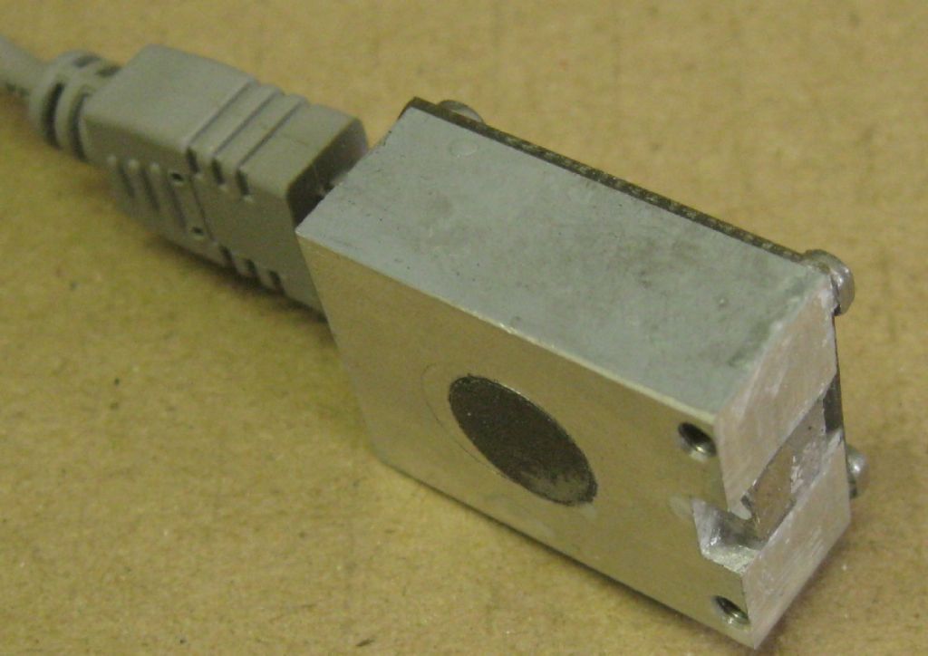
      One of the accelerometers – magnets on the Z and Y axes allow quick attachments and removal.

      accelorometer.jpg

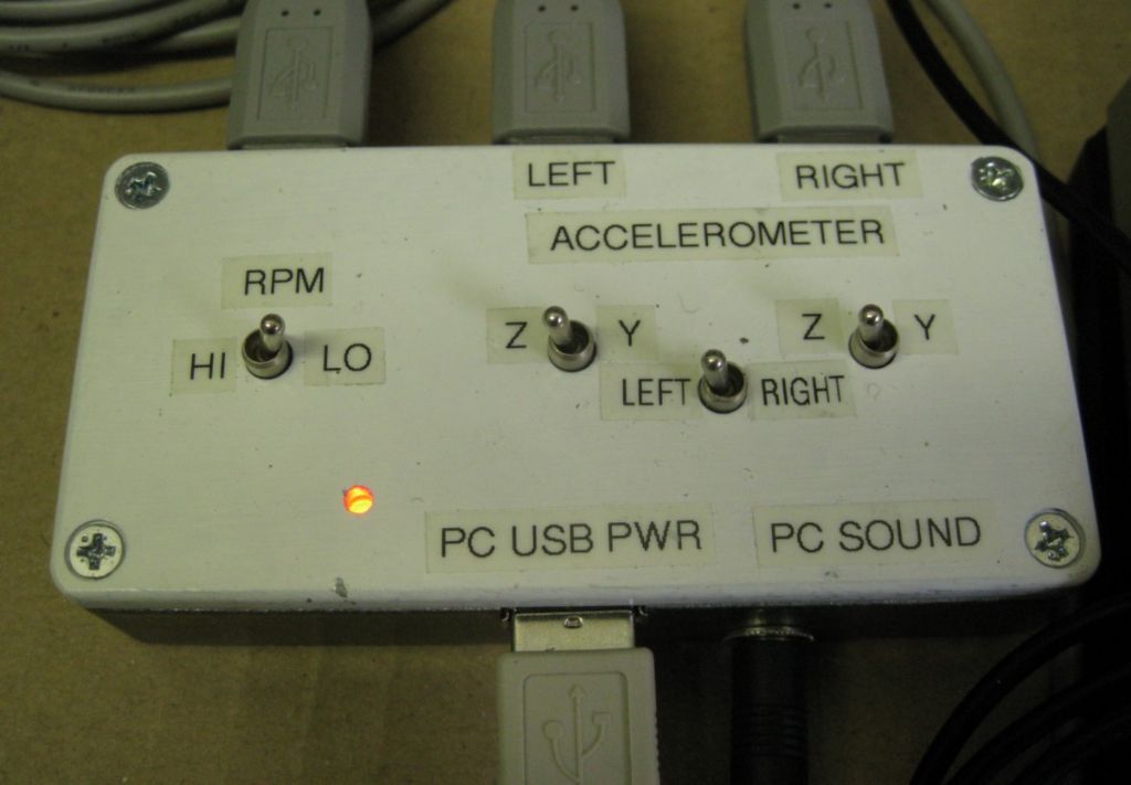
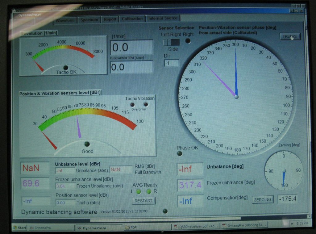
      The accelerometers, RPM sensor, all come to this interface box, where the correct planes can be selected. The signals go from here to the sound card in the PC, and the software does the rest..

      balancer interface box.jpg

      balancing software display.jpg

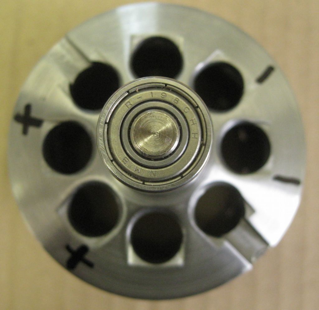
      Did not realise the camera focused on the bearing instead of the mass positions..The + signs show where the balance weights are added inside the rotor. The – signs show where to remove mass to balance. The two small weights were then removed and weighed.

      balance weight positions.jpg

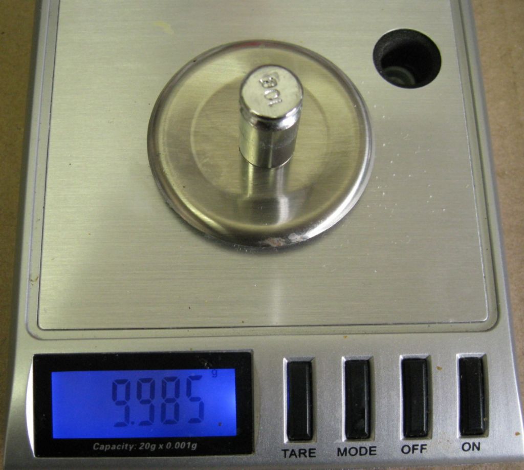
      A 10gram scale (0.001g 'resolution..) was used –  not accurate, but fine for comparative measurements.

      10gram scale.jpg

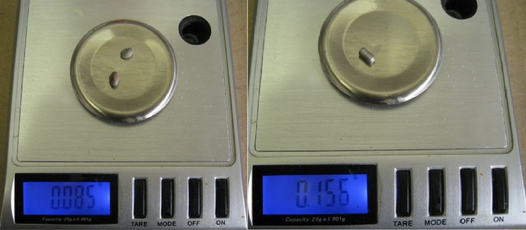
      The two weights were removed  and weighed. To get a feel for how big a hole to drill on the rotor inner to remove similar weight, an M3x5mm grub screw was weighed.

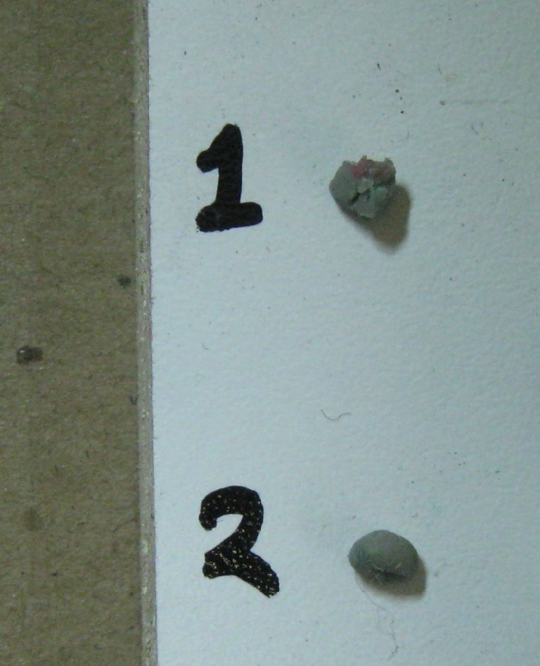
      The two little tackytape weights seen here:

      two balance weights.jpg

      The two weigh near 0.085g, the grub screw 0.156g, so need to remove 1/2 grub screw size, spread over the two balance positions.

      balnce weight mass.jpg

      The two holes are 4mm diameter, 1mm deep each. I started with 3mm x 0.5mm deep. Then 4mm x 0.5mm deep, and repeat deeper till done.

      final balance holes.jpg

      This was all repeated for the right side of the housing , while verifying effects to the opposite sides regularly


      Edited By Joseph Noci 1 on 04

      Advert
      #31378
      Joseph Noci 1
      Participant
        @josephnoci1
        #561464
        Werner Schleidt
        Participant
          @wernerschleidt45161

          Hello Joseph,

          a very nice test rig and test method! Perhaps i overlook it , how do you measure the angle? I do not noticed a sensor. There is a rpm sensor in the text, do you calculate over one period and calculate from one rpm over time of one revolution the angle?

          Werner

          #561627
          Joseph Noci 1
          Participant
            @josephnoci1

            Hello Werner,

            The RPM sensor is also used to reference the angular position. The RPM sensor is ringed in orange in the image below, the top left part. The Reference mark on the motor rotor is ringed in red in the same image.

            A reference calibration is done to start – A small mass, maybe 1 gram or less, is attached at the reference mark position ( the one ringed in red) and the rotor is spun up. The accelerometer then detects this imbalance, and it should coincide with the optical detection of the reference mark. Once calibrated, the software knows that the reference mark is 0 degrees. The reference mas is then removed, and when the rotor is spun up again, any imbalance is detected by the accelerometer, and the angle computed with reference to the optical reference mark.

            Hope that makes sense..

            Joe

            balance jig viewsrefsense.jpg

            #561638
            Robert Atkinson 2
            Participant
              @robertatkinson2

              What is the software you are using?

              Robert G8RPI.

              #561643
              Joseph Noci 1
              Participant
                @josephnoci1

                Software is DynamsPro – from Miklos Koncz in Hungary.

                Joe V51JN

                #561675
                Werner Schleidt
                Participant
                  @wernerschleidt45161

                  Joseph,

                  thanks for the explanation!. As you discribed it I had the idea how it can work.

                  Werner

                Viewing 7 posts - 1 through 7 (of 7 total)
                • Please log in to reply to this topic. Registering is free and easy using the links on the menu at the top of this page.

                Advert

                Latest Replies

                Viewing 25 topics - 1 through 25 (of 25 total)
                Viewing 25 topics - 1 through 25 (of 25 total)

                View full reply list.

                Advert

                Newsletter Sign-up