electronic cylinder indication
electronic cylinder indication
Home › Forums › Work In Progress and completed items › electronic cylinder indication
- This topic has 24 replies, 7 voices, and was last updated 16 September 2021 at 14:08 by
Werner Schleidt.
-
AuthorPosts
-
27 June 2021 at 15:40 #31368
Werner Schleidt
Participant@wernerschleidt45161test object 4 inch Garret
27 June 2021 at 15:40 #551614Werner Schleidt
Participant@wernerschleidt45161Hi folks,
i made some work with my electronic cylinder indication system. My steam friend Jürgen have a nice 4 inch Garret Traction Engine. Last year i showed here the video transport for live steaming.
Jürgen made some progress with the adjustment of the valve setting until he was satisfied. The engine run for him OK. But sometimes during start the engine behave in second gear like a wild horse. I had build an electronic measurement system to indicate cylinder and found some not good adjusted valve timming in my own locomotive. So I know how good such a setup is to tune the valve setting. With his Garret there is an additional problem, the valve setting changes from cold to warm,because the boiler length changes about 1.5 mm by calculation of the heat difference and length from the drive shaft to the cylinder.
My setup is based on a selfbuild rope displacement sensor with a return spring in it. It is able to measure 300 mm in total. With this i measure the piston travel.The pressure sensors for the cylinder pressure are capable to measure 12 bar. They are equipped with an integrated
electronic amplifier and are factory calibrated . It is an affordable China product. The data has been collected with an Arduino Nano and is able to work with 8 Channels. The sampling rate is 560 samples per channel per second.It is possible to measure the towing force , the speed and the temperature in parallel.
The software is my homebrew for the arduino and the laptop.
I used this system before to optimise my 5 inch locomotives. The attention is to increase the effiency and not the speed of an engine. I like traction engines which are in standby slowly ticking over and this is a sign for a good valve setting.
My hobbies are constructing steam engines and electronic systems. So is this a perfect symbioses of both for me.
So I convinced Jürgen and add the measurement system to his engine. At the first step the displacement sensor was tricky to mount and not good aligned, but the measurement correlate to the action of the engine. The next step was to construct a better attachment of the displacement sensor. Between me and him are many Kilometers in distance so i constucted it after pictures and it was attachable with some improvisation.
The pressure sensor was adapted with tubes, this was the only possible way to make it quick and dirty.
Please take a look at it. And for shure it is possible to work whitout such a system. Steam engine are very fault tolerant. If there are any question please ask.
Werner
Ps the outcome oft the video was , the engine run better after the first cahnge, but there is some room for improvement with an additional shift of the valve.
Very good is, the measurement and the practice behaviour is correlating.
Edited By Werner Schleidt on 27/06/2021 15:44:41
27 June 2021 at 21:38 #551658Nigel Graham 2
Participant@nigelgraham2A very interesting project.
The one point I might suggest with respect if you've not done this, it to place a water-block between the sensor and the cylinder, as on the boiler pressure-gauge, to protect the transducer from hot steam.
28 June 2021 at 05:58 #551671Werner Schleidt
Participant@wernerschleidt45161Hello Nigel,
in the video it is not good to see, in front of the pressure sensor is a copper tube with one turn for condensing the steam as it is normally made for pressure gauges.
28 June 2021 at 10:09 #551684noel shelley
Participant@noelshelley55608Hi Werner, I presume your device is an electronic version of the Dobbie-Mcinnes steam indicator ? How are you getting the piston position – by linear measurement or by angular from the crankshaft ? I also presume that by using 2 pressure sensors one at each end of the cylinder that you can read both ends in one operation ? Well done ! A very usefull tool to aid getting the valve events correct and therefore an engine to run at it's best. I for one would like to see more of how you did this. Thank you. Best wishes, Noel.
28 June 2021 at 12:44 #551697Werner Schleidt
Participant@wernerschleidt45161Hello Noel,
i do not know the Dobbie-Mcinnes steam indicator. In principle i measure the displacement by a multi turn potentiometer with a return spring. At the moment i have sensors for 300 and 250 mm displacement. So the piston travel is measured linear. The pressure sensors are connected to the draincock pipe at each end of the cylinder. This is equal to any kind of Indicators I saw in old books.
In two or three weeks we have our next steam meeting and so we tune Jürgens 4 inch Garret again. We will see how good we get the engine. I make a documentation again and I will try to show more details. But for me it is a one man show. With handling first my own engine , making a general video of us and then at the end of the session make the measurements and documentation. And it is working fine , but it is not a turn knob equipment.
Werner
28 June 2021 at 18:50 #551734noel shelley
Participant@noelshelley55608Hello Werner, Thankyou for the reply. The Dobbie- Mc innes indicator is an old piece of equipment that measures the travel of the piston and records the cylinder pressure – plotting the result using a pen recorder as a trace on a round drum with paper round it. You could only do one end at a time.
I know a little about electronics and if a rotary encoder was used as well as 2 pressure transducers then you could see/record not only both ends but also any number of strokes. A digital storage osilloscope might work ? Good Luck and best wishes. Noel.
28 June 2021 at 20:44 #551758Werner Schleidt
Participant@wernerschleidt45161Hello Noel,
i know the Maihak Indicator, but they are all similar. With my displacement sensor you see in the time diagram each stroke very clear and the pressure at each millimeter of piston travel.
My Software is quasi a digital storage oszilloskop software with the possibility to store in a file and show it in a
XY chart or here is it the indicator diagram . I can measure 8 Sensors in principle two independant compound cylinders with two setups 2 times diplacement and four pressures.
Werner
3 August 2021 at 12:55 #556839Werner Schleidt
Participant@wernerschleidt45161Here is an update of our activies from sunday. We made a steam meeting with four road steamers.
At the beginning as the engine was cold we change the valve setting of the Garret. With the electronic steam indicator we had after studying the measurements the idea to shift the valve 1.5 mm to the chimney to equal the pressure curves of the valve chambers. In total we changed 3 mm since the beginning. After the engine was under steam it was noticeable that the flywheel runs much smoother as before. Juergen made two long runs with 2..6 and 3.6 km and noticed a much improved consumption of water and coal. A great benefit is that the engine is now better to handle in slow driving. He is really satisfied now. His codriver Stefan noticed independantly the same.
Here is the documentation of the control measurements. It was a little bit difficult to film , the interest of the steam colleages was great,but very often someone blocked the camera.But for documentation it is enough. I tried to make it understandable and I hope i reached this goal.It was a good step from subjective feeling now it is Ok ,to see it on the diagram that it is OK. Always fascinate me a smooth running or ticking over engine.Juergen is with the improvements very happy now. I recognized which a good tool I made . The first tests were made with a small 5 inch locomotive and now the big Garret Traction engine for another experience.I hope you can enjoy and understand what we have done.best regardsWerner7 August 2021 at 20:53 #557471vic francis
Participant@vicfrancisGreat work Werner!!
And utube explanation! I wondered why at the rhs end the graph line dips down , and bounces back up… ? What was causing that do you think?
Have you tried this on your Fabulous Fire King Fire Engine yet? With or with out the Turbinators in operation? From the utube videos your machine looked spot on perfect already! Certainly clean running, and long runs!!
Vic
8 August 2021 at 08:58 #557502Werner Schleidt
Participant@wernerschleidt45161Hello Vic,
thank you!
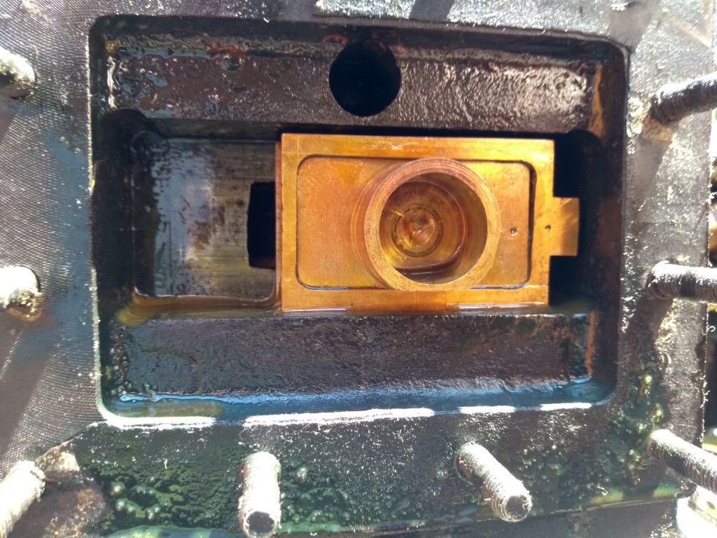
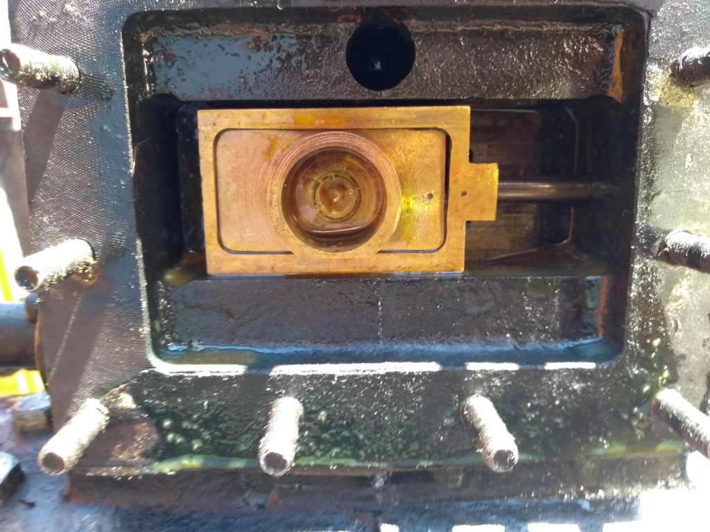
I try to explain what you want to know. I made a picture of Juergens valve gear and there is to see that the valve steam channels are casted. The blue side movement from chimney to gear or the rhs in the diagram is not very accurate. The shape is not with straight cut as it is achieveable if it is milled.

For my opinion is this the reason in combination with some marks on the valve running surface that there is in this area the valve is not perfect steam thight.
The steam channel on the gear side is more accurate and straight. But in the picture it is not very good to see.
And there are many marks on the surface too.
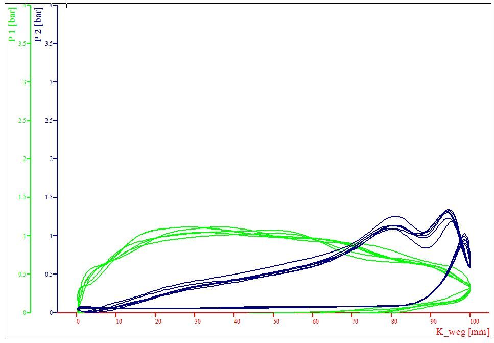
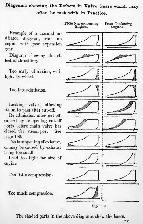
When I look in old books i found that from 90 to 100 mm piston displacement the blue curve comes up and the reason is that the steam port to the chimney is closed and there is some compression. Therefore at about 100 mm there is then steam comming in and this cause in a slope, because steam pressure is lower then the compression pressure at this moment of opening the valve. To make this perfect the valve have to be a litlle bit machined in the inside to allow the steam to come earlier to the chimney. If green where mirrored as a blue curve this will be better.
If we look to the curve in the old book there is an example which is discribed with too late admission.
Juergen made the excenter settings with not very good explanations in the plan, as he told me. He had to interpretate some dimensions. And it was clear he had to decide to screw down the excenter after his measured dimensions. I think the result, after this possibility of possible mistakes, is very good.
Juergen want not to change anything in the beginning, he was satisfied with what he had achieved. As I show him which i achieved with my little loco Plettenberg with the first tests of the electronic cylinder indication setup, he gave me a try. I made then some attachements for the rope displacement sensor and the electronic.
The first base measurements were made with lot of improvisation during standing without load. This was not good. The best behaviour for measurements is slow running ~ 120 -200 RPM and under load. As you see in the diagram, there is a very low steam pressure ~ 1 bar during driving in the cylinder.
The pressure sensors are connected with tubes, because he had no possibility to screw the sensor pipes to the cylinder. But in the other hand it is good to see that the measurement setup is in function with this circumstances.
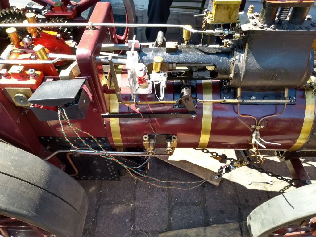
Here is a closer view of the sensor attachment. For me it is a little bit difficult ,because i make all pictures, video, computer, measurement and calibration by my own. Therefore I was happy Stefan the friend of Juergen helped me with the steam engine.
The rope sensor have been build by my own with a multi turn potentiometer and a return spring from an identiy card jo jo. Herbert a modelflying colleague sponsored me with fine steel wire . The accuracy of the rope sensor is in the range of 0.1 mm by 300mm displacement. I compared it to a digital gauge at my mill. This is much better then we need for this measurement.
The pressure sensors are chinese ones and i compared them to a pressure gauge with a good result. And they are low cost. The electronic is based on an arduino nano with bluetooth transmitting to the laptop. The software is my homebrew based on freebasic and is coming from DOS times with GW basic. In the field it is easier to act with key commands as with scroll down menus. So it is very good for this kind of work.
Juergen is now very happy with the valve adjustment and measurement. He made long runs of 2.6 an 3.6 km and noticed remarkable less coal and water consumption. And he can drive now very slowly and the engine starts now smooth and not like a wild horse as it was in the beginning.
In the next time we measure another engine. This one is older and have a very good run in.
It will be very interesting to see how this performance is in relation to the measured diagrams.
best regards
Werner
8 August 2021 at 09:17 #557504Werner Schleidt
Participant@wernerschleidt45161Here is the diagram with the principal indicator diagrams.
It is from the Handbook on steam engines from Haeder and Powles 1902.
Thanks to Vic who sponsored me with informations and web links!
This is taken from the side 383
The left curve number four with late admission fits to the kind of the measured curves and number two throttlling. For the power of the engine we had during the measurement to less load . Normally the engine have to pull a wagon with some adults as load.
Werner
8 August 2021 at 09:45 #557508SillyOldDuffer
Moderator@sillyolddufferExcellent work Werner! Good to see the diagrams being used to improve the engine's performance.
I had no trouble translating Biergarten from the video, but what is K_weg (mm) on the graph? I know it's piston distance ('weg'
 , but what's the K_ ?
Impressed: tasty traction engine with sensors producing computerised indicator diagrams explained in both English and German!
And thank you for publishing the Haeder and Powles diagrams.
Cheers,
Dave
8 August 2021 at 10:17 #557513Werner Schleidt
Participant@wernerschleidt45161Hello Vic,
a few words to my fire king. It is roughly planned to make indicator measurements too. But this have not so a high priority.
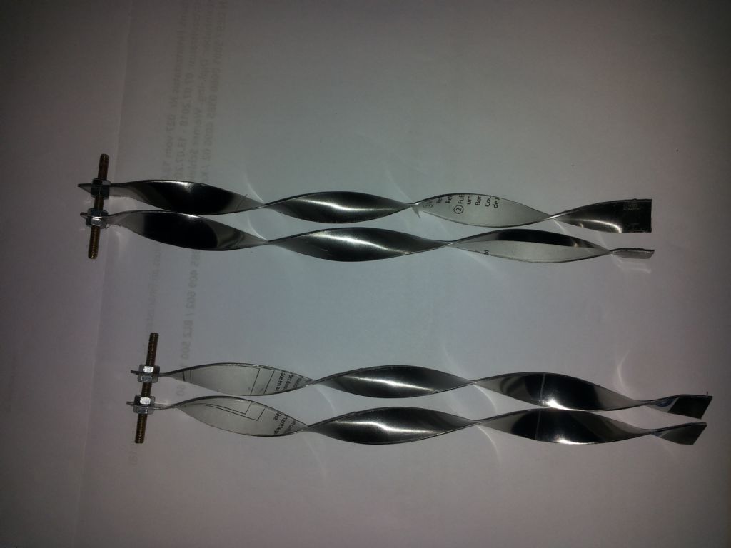
The steam engine had a remarkable improvement of the boiler and fire performance with the added steel stripes in the fire tube which is normally for the superheater pipe. Many thanks to Johannes, known as Yorkshire Man, he gave me the hint in a german forum. So i gave this idea a go and test it at my fire king boiler.
This stripes hang in the middle wide tube of the boiler. This stripes force the exhaust around this stripes and add some resistance for slowing down the gas velocity. So the exhaust gas have more time to add heat to the boiler.
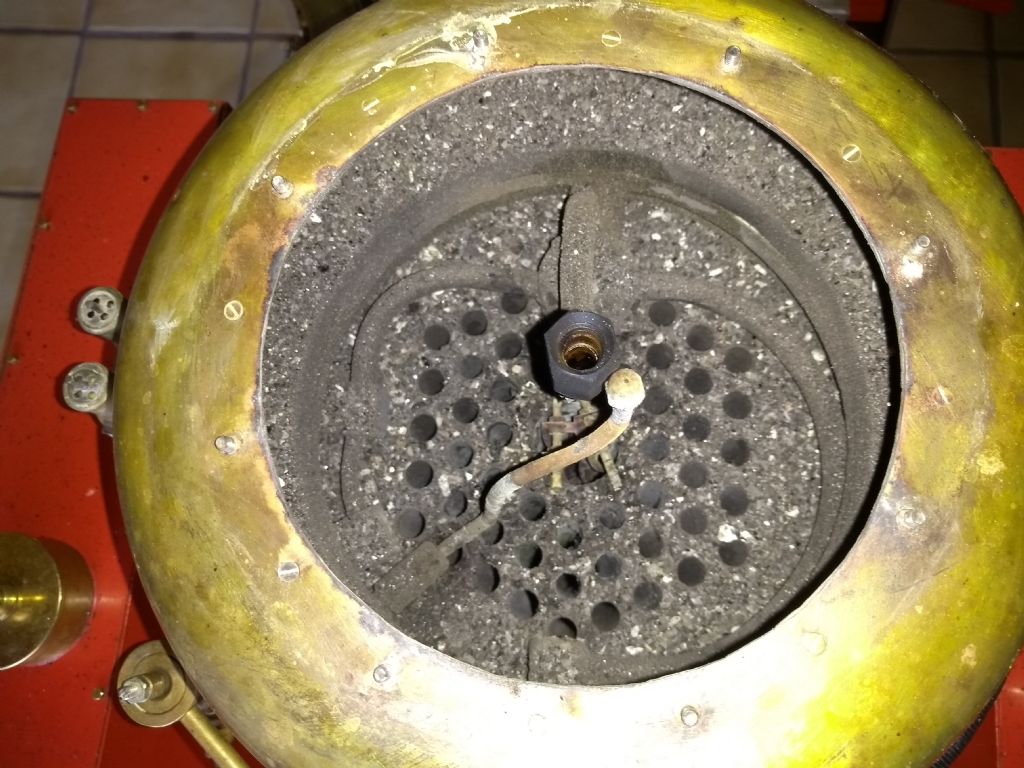
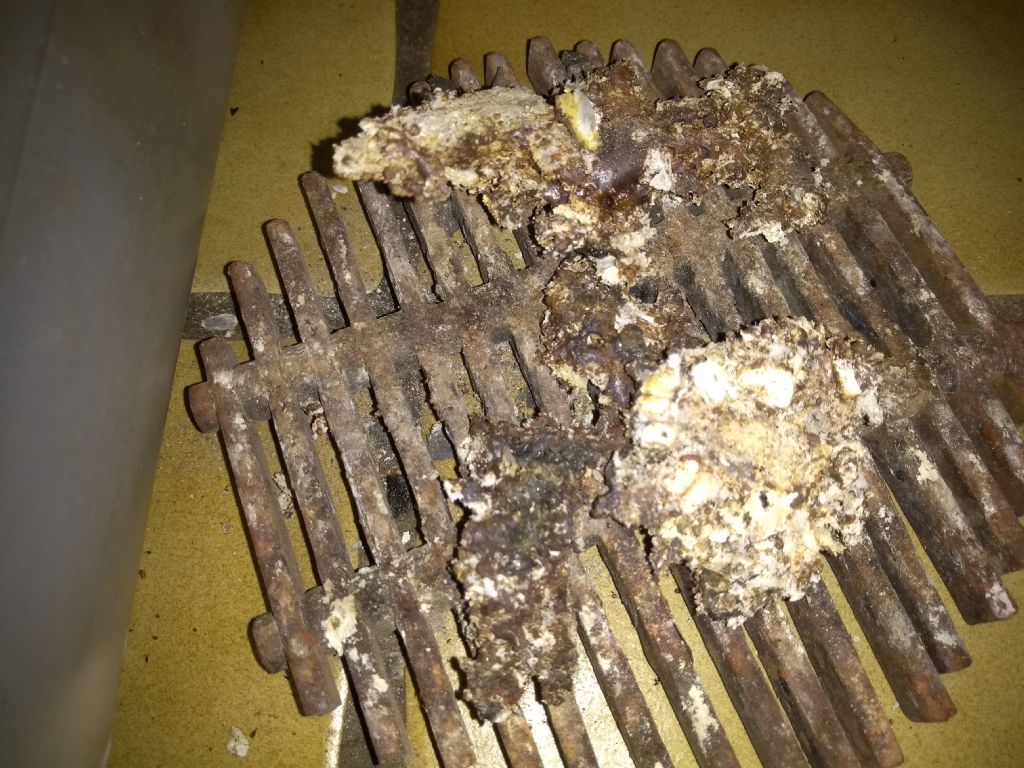
The change was remarkable. I could drive after this with continous blowing safety valves and the fire burns much better. There was only like black sand in the smoke chamber. Before there were much more bigger unburned coal parts and sparks. I changed then the exhaust nozzle to a wider bore. This gave the steam engine less back pressure and so the RPM and power increased. The fire burns a litlle bit worster ,but much better then before I made all this changes. If i drive continously and do not forgot to add coal regulary , I can drive permanent with a pressure short for blowing of. I can control the pressure by adding water or not.
Here is a photo with the setup and the changed exhaust nozzle after 11 Km of driving.
And here is the clinker after this ride
This was a big improvement.
I made measurements with a thermocouple to measure the exhaust temperature and it was clear to see that the fire burns much better.
More information in the thread Merryweather Fire King self propelled
Werner
8 August 2021 at 10:33 #557515Werner Schleidt
Participant@wernerschleidt45161Dave ,
K_weg is the short form for Kolben Weg or better to understand piston travel. Your deduction was correct.
I try to make it so understandable as possible, but I see there is room for improvement. The same I learnt from my colleagues, at our driving area , they see all ,got explanations, but with the video and additional explanations they understand it complete.
I know it is diffcult and I worked in my profession with complex professional equipment. So something is for me known and I had to explain it for others ,who see this the first time.
If i study the old books it is very remarkable what was known and in this times forgotten now.
best regards
Werner
Edited By Werner Schleidt on 08/08/2021 10:46:12
13 September 2021 at 08:08 #562577Werner Schleidt
Participant@wernerschleidt45161Hello all,
we made another meeting with our steam friends. Jürgens Garret Traction engine have now a correct valve setting , based by the investigation of the electronic cylinder indication. On the end of the video there are two sequences were the engine is set to a very slow rpm . Now the engine have a fine driving behaiour and the coal and water consumption is remarkabel less than before.
Have fun with the video.
Werner
13 September 2021 at 09:51 #562587Nigel Graham 2
Participant@nigelgraham2Fine work, and a very interesting discussion.
I worled for a company making sonar equipment and did ponder the possibilities of a piezo-electric pressure-sensor for engine-indicating. I found that in fact this was being done in the 1930s for testing i.c., particularly large (marine and plant), Diesel engines.
'
Some have mentioned the Dobbie-McInnes Indicator.
In this, the steam pressure acts on a piston against a calibrated spring, and the amplitude of its motion is recorded against the scaled-down stroke on a pro-forma card clipped round a drum rotated by a cord and return-spring, driven from the motion.
To keep the indicator-card and the whole instrument compact but suitable for more or less any engine stroke, the drum cord is not attached directly to the cross-head but via a reducing-lever, either one attached for the test or some point on the lubricator-drive arm.
'
Engine Power:
The diagram gives more than the valve-effects and pressure at any point. The area it encloses leads to calculating the power generated by the steam inside the cylinder, hence "Indicated Horse Power" (IHP) – or indeed in Watts, of course.
Originally the area was detemined by tracing the loop with a 'planimeter', a manual, mechanical integrator; with the card clipped to a suitable flat surface. I don't know the mathematics and programming, but would the electronic system allow this from the transducer and piston-travel data?
(The early electronically-measured indicator-diagrams could be analysed only by connecting the transducer to an oscilloscope, photographing the trace then measuring the print.)
The output power available for the intended work, is the Brake Horse Power (BHP), measured from a dynamometer.
13 September 2021 at 18:06 #562641Werner Schleidt
Participant@wernerschleidt45161Hello Nigel,
I know that for internal combustion engines piezo electric pressure transducers were used. One special brand is Kistler from Swiss, they have a good knowledge and reputation. But there parts are extremly expensiv.
For this job the china made transducer are in the range of 20 € and this is no problem and they are precise enough.
My homebrew software is able to measure the rpm of the engine and the average pressure during running. And with this i am able to calculate the engine power. For valve setup investigations this is not useful, because normally we run the engine not under full power there is normally a throttle valve in front of the cylinder. The Garret of Jürgen is extremly powerfull there is no easy way to brake the engine to get a full power diagram.
And with my small 5 inch locomotives it is the same.I had to use a brake locomotive it is the same as they do it in full size. I tried to make a test on track with cylinder indicated power in comparison to Power at the dynamometer and speed of the wagon. This gave partly some good and some strange results and i found that our track is not in horizontal level. I have to use my electric locomotive as a brake loco to charge the battery.
But then came winter and corona and so all investigations were on hold. I have more ideas then capacity to do all.
Electronic cylinder indication is a good tool for fine tunnig the valve setting and this is the main function i use. And it is much better then the try and error method i use before. And i am very astonished with which small changes a very different driving behaviour is possible.
Werner
13 September 2021 at 18:30 #562647duncan webster 1
Participant@duncanwebster1Farnell have sensors for as little as £13+vat, I think they are strain gauge type and made of plastic, but should be useable with care to add heat isolation
I think the linear sensor for a 5"g loco is a bigger challenge
13 September 2021 at 23:26 #562703Nigel Graham 2
Participant@nigelgraham2Not sure if a strain-gauge sensor would work in this situation, heat-isolation apart.
The senosr needs a flat frequency-response from a few Hz up to several 100Hz, so that for example the admission pressure reading is equal across the engine's own range from tick-over to maybe the 300-400 rpm on a steam road vehicle.
Even if the strain-gauge itself could follow the pressure-variations it has to be mounted on a substrate or diaghragm that may not be sufficiently linear except at very low speed.
A piezo-electric probe is probably the better bet for higher speeds, and I think suitable ceramics are available quite easily and cheaply. They are after all used in telephones, buzzers, door-chimes, etc. (As a guide the note Middle A at 440Hz – matches roughly the typical full speed rpm of an overtype steam-wagon engine. Or perhaps a miniature loco on a rolling-road?)
It needs a suitable amplifier as the voltage output is tiny.
Nevertheless, an interesting area of experiment and study.
14 September 2021 at 00:24 #562710duncan webster 1
Participant@duncanwebster1I'm wrong, the top one on the link is piezo. Max pressure oscillation frequency is more like 10hz. Railway locos were designed for ~6 revs/sec, models a bit faster.
The sensor is rated for 120C, so you don't need much heat dissipation, length of copper pipe and a cooling fin, even better stainless pipe
14 September 2021 at 17:37 #562803Howard Lewis
Participant@howardlewis46836Good Work, Werner!
Very pleasing that your work enabled Jurgen's Garret to be so improved. Electronic sensors allow measurements to be taken and shown at higher engine speeds.
Your work is pioneering! And others will, also benefit from it.
I like the "Driver" on your Merryweather!
On high speed (2100 rpm ) diesels, in 1959, we measured cylinder pressures by balancing a floating diaphragm with Nitrogen from a gas cylinder until it balanced cylinder pressure, and there was no movement of the diaphragm.
On the flywheel was a Tufnol disc with magnets in slots (one the opposite way round to show tdc ) to give angular position, and speed, relative to a pick up coil)
Diaphragm movement changed capacitance and the frequency of a VHF amplifier, so that when the frequency became constant, we knew that the diaphragm was balanced and the pressure could be read off the gas cylinder. Slow by modern standards, but this was cutting edge technology at the time. (The amplifier was a valve one, 300V DC on the anodes! The Mullard OC71 transistor was new! )
Progress has made life easier!
Howard
14 September 2021 at 19:53 #562824Werner Schleidt
Participant@wernerschleidt45161Hello all and many thanks for your interest!
I want to add more information about the sensors.
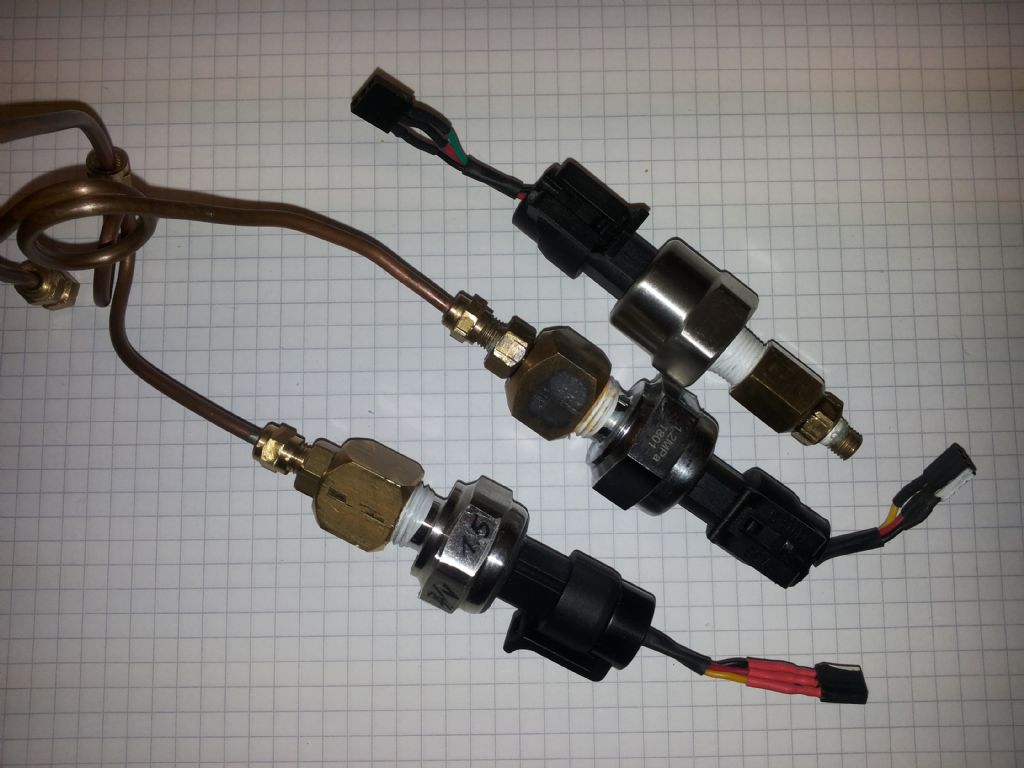
The pressure sensors are china made ones in a stainless steel housing with diaphragma and strain gage amplifier and ready calibrated. They are made for 5 V excitation and have a range from 0.5 volt to 4.5 Volt. I compared them with a normal Pressure gauge with good results. For my software i marked them with the parameters i have to add in the software for the correct span and zero adjustment.
I made adapter from 1/8 BSP and 1/4 pipe thread to M6*0.75 mm for easy use with my model applications. The sensor is very cheap ( < 20 &euro
 for the quality and good for field measurements. I found no noticeable drift.
The connectors had been changed to rc model type ones they are simple and cheap. If they were pulled out by accident there is no damage possible. I secure them with tape and add numbers or a discription to know hwere they are installed.
Part 1
Werner
15 September 2021 at 17:58 #562936Werner Schleidt
Participant@wernerschleidt45161Part 2
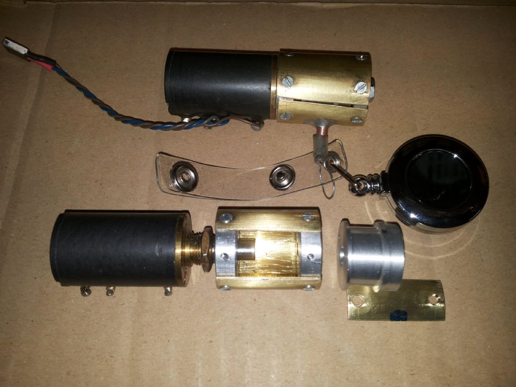
The displacement sensor or the piston travel sensor is more tricky. I want to have a sensor who is on small and bigger engines possible to install. I had an incremental angle sensor this is very accurate but it have to be attached to the axle or flywheel and that is not so easy without changes at the model or object. I get by chance a very fine LVDT displacement sensors with a carrier amplifier and inbuilt electronic. To meassure 100 mm the sensor is about 300 mm long. This is difficult to mount. So i came to the results that the sensor mechanism with a rope like in the old indicators is very favourable. So i thought about about how i can build a sensor. In my former job i know rope displacement sensors based on a rope a return spring mechanism and a rope drum and a potentiometer. This parts are very expensiv , the range is from 500 to 1000 €
So i construct my own. The base is a multiturn wire potentiometer with 5 Kohm , a drum which is coupled with the potentiometer axis and a return spring i got from a identicard jo jo. This were my parts which play together to operate the rope sensor. My modelplane colleague Herbert sponsored me with thin multiwire control line rope.
It was very tricky to bring all parts together and after the first one i made two others all in a range of max 300 mm. I tested them in comparison to my digital gauge at the milling machine. The measurements were very repeatable and with a good accuracy. I added a small amplifier with a filter for cutting noise and with a level shifter for easy zero shift adjustment. The span was precalibrated at the amplifier and a fine calibration can be made by software. All sensors have a unique calibration file, but the rope sensor are very similar.
To give you an idea from my sensor
The spring is in the frontside of the drum . In the front cover of the housing there is a screw which is the spanner for the spring. The tricky part is adding the rope winding by winding in the right direction and spanning the clock spring and setting the potentiometer at the correct position. This is a four hand job, but with several try's it worked good. The amplifier ist then attached to the potentiometer and then it was added some heatshrink tube. Then the parameter and calibration was measured and marked at the sensor.
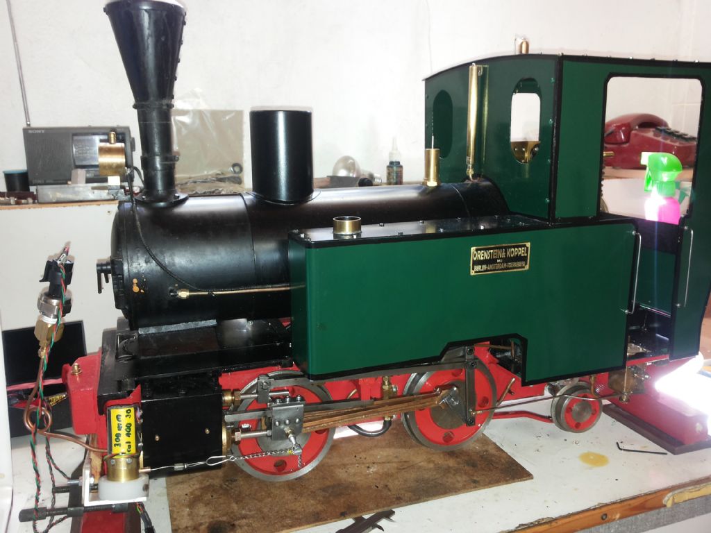
In the next picture it is adapted to my loco for measurement.
The pressure sensor is connected to the cylinder cover. The rope sensor is mounted with some improvisation with clamps and wooden bars at the front. The rope is connected to the crosshead by a chain and a adapting screw. The white PA part allows clamping of the sensor and some adjustment.
part 3
Werner
Edited By Werner Schleidt on 15/09/2021 18:03:05
16 September 2021 at 14:08 #563030Werner Schleidt
Participant@wernerschleidt45161part 4
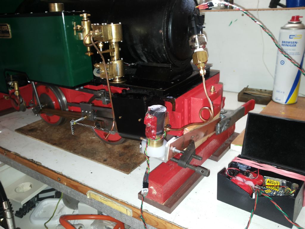
This is the similar installation on the right side

In the small box is an arduino nano with the connector bank for the eight analog channels , the bluetooth modul with 115 Kbaud and the power supply based on old laptop cells. The power supply is able to work with eight sensors for two to three hours.
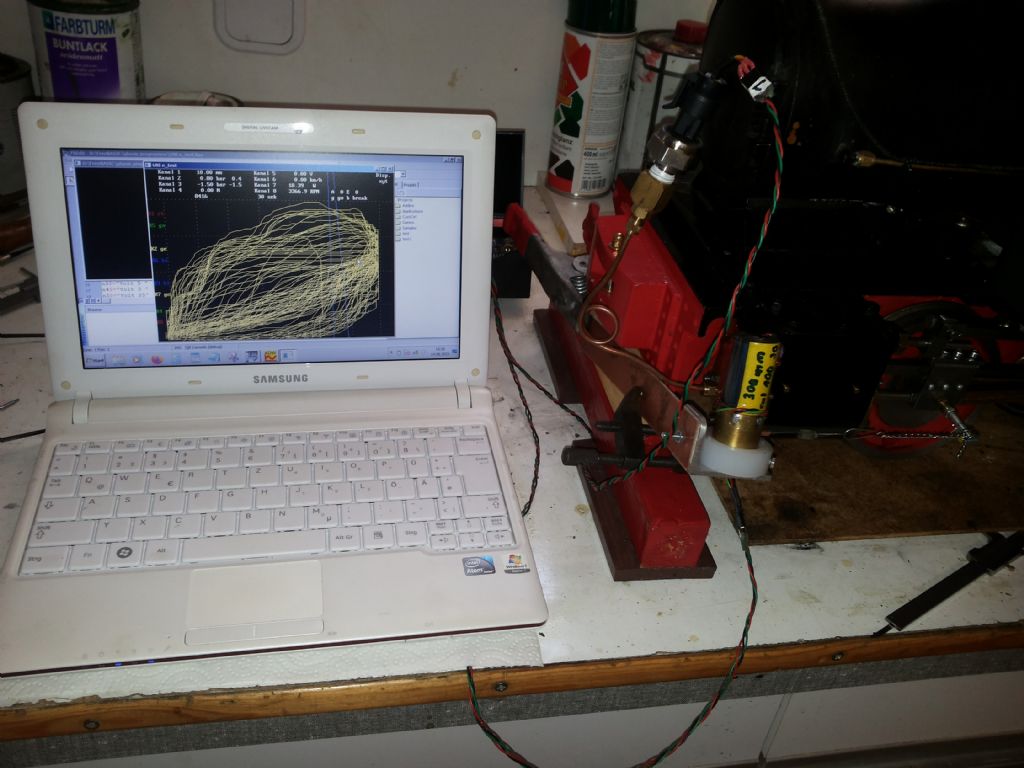
On the laptop screen there is a test measurement of 30 secs to see.
In these many curves is the start , some braking with load and the stop to see. This is a kind of overall info as you can see it during measuring .After the stop the data have to be stored. I can measure several tests and store them with usefull short names. After a stored measurement i can reload it and look in the time frame for interesting parts. In the time frame i can look if there are two to three similar curves and with the start and end point I can plot them then in a xy diagram. Is this in running condition on the track i calculate the average pressure and the rpm of the engine. With the piston size , travel ,rpm and average pressure the power in this cylinder chamber can be calculated. This is possible but it is difficult to run the engine under full load. I use the system as a tool to see the begin of steam come in and the shape of the curve. So i can adjust the valve gear. I do not like try and error methods as i made it befor i have this system.
My experience at the moment is, it work good, gives good results , but the software and the procedure how to measure need some fine tunning for more comfortable use in the field. And one thing is at the moment clear, i see it as i measure Jürgens engine. All visitors are exited to see the result immediatly and this is only possible to see in the overview as it is in the picture above. I have to add in the software during measuring some markers for the constant driving or something like that.
Over the winter I think i can make some fine tunnig based on the experience i had now.
Werner
Edited By Werner Schleidt on 16/09/2021 14:11:42
-
AuthorPosts
- Please log in to reply to this topic. Registering is free and easy using the links on the menu at the top of this page.
Latest Replies
Home › Forums › Work In Progress and completed items › Topics
-
- Topic
- Voices
- Posts
- Last Post
-
-
Electronic leadscrew pitching error
Started by:
paulg 1 in: Introduce Yourself – New members start here!
- 4
- 13
-
14 July 2025 at 21:46
 Robert Atkinson 2
-
Error-Message of the day
Started by:
 Michael Gilligan
in: The Tea Room
- 6
- 7
-
14 July 2025 at 21:40
Versaboss
-
Silver steel crankshaft
Started by:
teamricky in: Stationary engines
- 7
- 20
-
14 July 2025 at 21:32
teamricky
-
Farm Boy
1
2
…
4
5
Started by:
Dalboy in: I/C Engines
- 15
- 104
-
14 July 2025 at 21:26
Dalboy
-
Another Day … Another ScumBag
1
2
Started by:
 Michael Gilligan
in: The Tea Room
- 15
- 35
-
14 July 2025 at 21:19
bernard towers
-
Adjustable spanner thread direction
Started by:
 jimmy b
in: Workshop Tools and Tooling
- 9
- 10
-
14 July 2025 at 20:00
old mart
-
Volt/amp meter
1
2
Started by:
duncan webster 1 in: Electronics in the Workshop
- 15
- 40
-
14 July 2025 at 19:54
 Michael Gilligan
-
Screw cutting 1.25mm pitch on a Colchester Student.
Started by:
Kevin Nicholls in: Manual machine tools
- 7
- 16
-
14 July 2025 at 19:03
bernard towers
-
“swedish iron”
Started by:
moonman in: Materials
- 15
- 19
-
14 July 2025 at 17:46
John MC
-
Variable DC power supply?
Started by:
Andrew Tinsley in: Electronics in the Workshop
- 4
- 10
-
14 July 2025 at 17:27
Andrew Tinsley
-
Sat nag
1
2
Started by:
duncan webster 1 in: The Tea Room
- 20
- 42
-
14 July 2025 at 11:41
 Bazyle
-
Boiler Design – issue 4765
1
2
…
8
9
Started by:
Charles Lamont in: Model Engineer & Workshop
- 26
- 201
-
14 July 2025 at 10:06
 JasonB
-
TurboCAD – Alibre File Transfers.
Started by:
Nigel Graham 2 in: CAD – Technical drawing & design
- 7
- 24
-
14 July 2025 at 09:09
 JasonB
-
Indicators – vehicle
Started by:
Speedy Builder5 in: Electronics in the Workshop
- 4
- 6
-
14 July 2025 at 06:02
Speedy Builder5
-
buying machine tools from aliexpress experiences?
Started by:
Jake Middleton-Metcalfe in: Manual machine tools
- 16
- 20
-
14 July 2025 at 02:13
Neil Lickfold
-
Electroplating questions
Started by:
Baldric in: Help and Assistance! (Offered or Wanted)
- 3
- 3
-
13 July 2025 at 13:42
noel shelley
-
Difficulty in sourceing 2.5mm s/s ‘Full’ nuts
Started by:
Greensands in: General Questions
- 7
- 12
-
13 July 2025 at 09:22
Roger Woollett
-
Rotary valve engine
Started by:
AStroud in: Stationary engines
- 2
- 3
-
13 July 2025 at 08:49
AStroud
-
Sanjay’s Banjo Engine
Started by:
 JasonB
in: Stationary engines
- 3
- 12
-
13 July 2025 at 06:50
Diogenes
-
I’m Under Pressure
1
2
Started by:
howardb in: Related Hobbies including Vehicle Restoration
- 17
- 31
-
12 July 2025 at 22:00
Howard Lewis
-
Help for DIY lathe build.
1
2
Started by:
moogie in: Help and Assistance! (Offered or Wanted)
- 16
- 36
-
12 July 2025 at 21:42
Howard Lewis
-
New Member From The Isle of Man
Started by:
sprocket 3 in: Introduce Yourself – New members start here!
- 4
- 4
-
12 July 2025 at 20:57
Howard Lewis
-
The Silver Swan Automaton
Started by:
James A in: Related Hobbies including Vehicle Restoration
- 3
- 5
-
12 July 2025 at 18:46
James A
-
Model Turbines
1
2
…
24
25
Started by:
Turbine Guy in: Stationary engines
- 28
- 607
-
12 July 2025 at 16:28
Turbine Guy
-
Nozzle dot dwg
Started by:
 Michael Gilligan
in: CAD – Technical drawing & design
- 1
- 1
-
12 July 2025 at 14:47
 Michael Gilligan
-
Electronic leadscrew pitching error
-


 , but what's the K_ ?