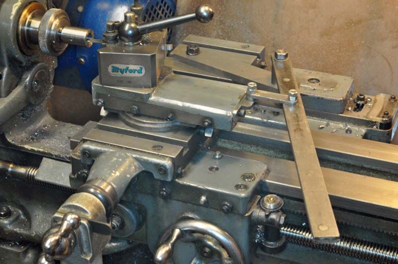
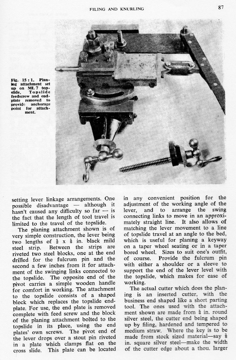
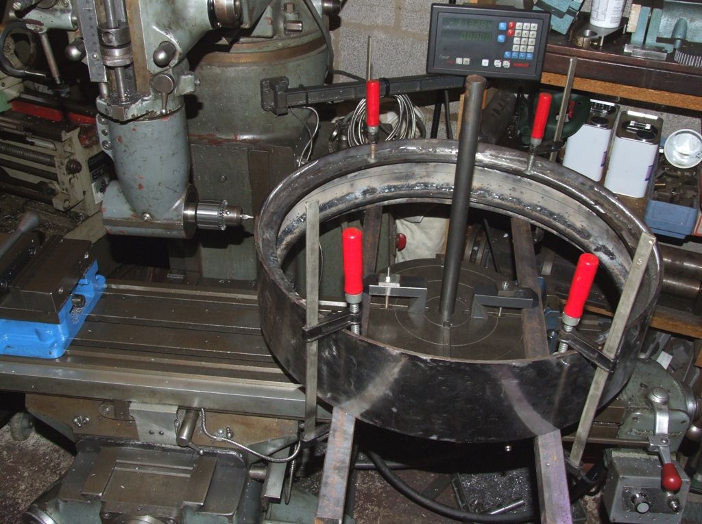
Following my asking for ideas a while back on cutting keyways, it's not really good for the lathe to use it as a key-way shaper. It tends to put a rather unfair strain on it, somewhat different from normal turning loads. It can be done, on small key-ways, with fine cuts, but it's not a habit to cultivate.
It can only be done by hand on a conventional lathe because the drive to the saddle is via the mandrel – but I would advise not even thinking of doing it under power.
However, by sheer chance an hour or so ago I was thumbing through a random bound volume I happen to have, of Model Engineer & Electrician (as ME was called then); and encountered an ingenious solution to this.
The writer made a key-way cutter in the usual way: a bar with a projecting cutting-tip; like a boring-bar but with the cutting edge facing forwards. This is held in the tailstock chuck.
The part to be keyed is set on a thick "table" as he called it (plate rather like a chuck back-plate) mounted on the faceplate or 4-jaw chuck, and the tool fed through it by using the tailstock hand-wheel, taking a few thou at a time.
That's the internal keyway. For the external one he set the cutter in a radial hole in the table, and fed the work into that.
In both cases the cut is advanced by adjusting the protrusion of the cutter from its bar; and the thrust was taken by the tailstock whose line of action is much closer to the cut. He was using a Drummond lathe, he wrote, about the size of a Myford 7.
'
The same volume also shows a rather neat key-way cutter in which the tiny cutter pivots on a pin to relieve it for the return stroke; but in practice a rigid mounting never seemed to hurt. The key-ways in hefty great full-size lumps like locomotive driving-wheels were cut on slotters that didn't appear to have any such relief.
'
If you need re-bore or recess the centres of a gears the problem is holding it accurately without harming the teeth.
The obvious is wrapping it in a steel or aluminium strip and clamping it in a 4-jaw chuck, or clamping it by the face to a faceplate; and to centre it with the DTI running very carefully against a close-fitting bush protruding from the existing hole. Of indicate off the teeth but be careful not to let the probe catch between the teeth.
Another is to mount a thick mild-steel or aluminium disc on the faceplate, and leave that undisturbed through-out the rest of the task. Starting with the smallest wheel, bore the disc to hold the gear by a gentle push-fit, locking the gear in place with clamps acting on its face. After machining that wheel, re-bore the plate to take the next one up…
(That would also work for holding things like pulley sheaves.)
Dr_GMJN.


