3 x 5 twin Victorian workshop steam engine restoration
3 x 5 twin Victorian workshop steam engine restoration
Home › Forums › Work In Progress and completed items › 3 x 5 twin Victorian workshop steam engine restoration
- This topic has 33 replies, 12 voices, and was last updated 10 September 2021 at 10:00 by
Mike Hurley.
-
AuthorPosts
-
25 November 2020 at 09:39 #509733
Mike Hurley
Participant@mikehurley60381The 3 x 5 twin Victorian workshop steam engine
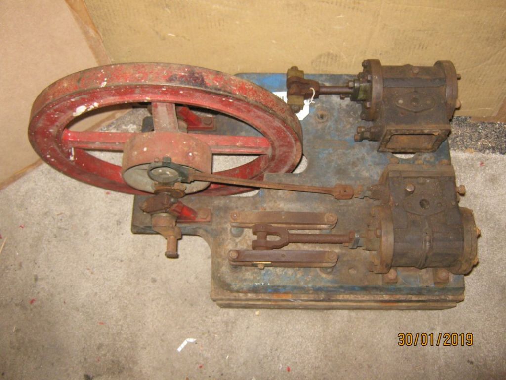
Begun as a retirement major project in early 2019, this has been a most interesting (if not frustrating at times) labour of love I suppose. I've learnt an awful lot; as though I have been dabbling in engineering for many years I never approached anything on this scale before.
About 2 foot long Base and 18" across, with an 18" dia flywheel plus pulley for flat belting. All very heavy (about 60KG in total) so a useful keep-fit exercise tool when moving it around!Described by the sellers as "a 3 x 5 twin Victorian workshop steam engine suitable for restoration…" with a fair description about the rust and missing bits – so had a reasonable idea of what I was letting myself in for.
I estimated that the majority of tasks would be just about within the max capacity of the kit I have.
Also worth mentioning that this was also a big learning curve for me, as I went along I tackled jobs that, on reflection, could have been done better,easier or perhaps quicker. If anyone comments '..why didn't you do X this way…….' I probably already thought of that in hindsight! If not, then I've perhaps learned something new – so thank you.I made the decision to try and return it to as near original condition as practical, refurbisihing as much as possible. I would try to ensure replacement parts were of a style typical of the era. I had no instruction book! I also didn't have a makers name so it proved impossible to trace anything specific. I researched many similar engines but still had to 'wing it' at times.
Started by documenting and measuring everything. Lots of photos taken for later reference. Once I had all that in situ I started to attack with spanners, oil can, wire brushes etc.

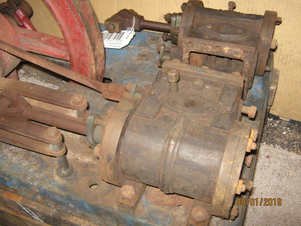
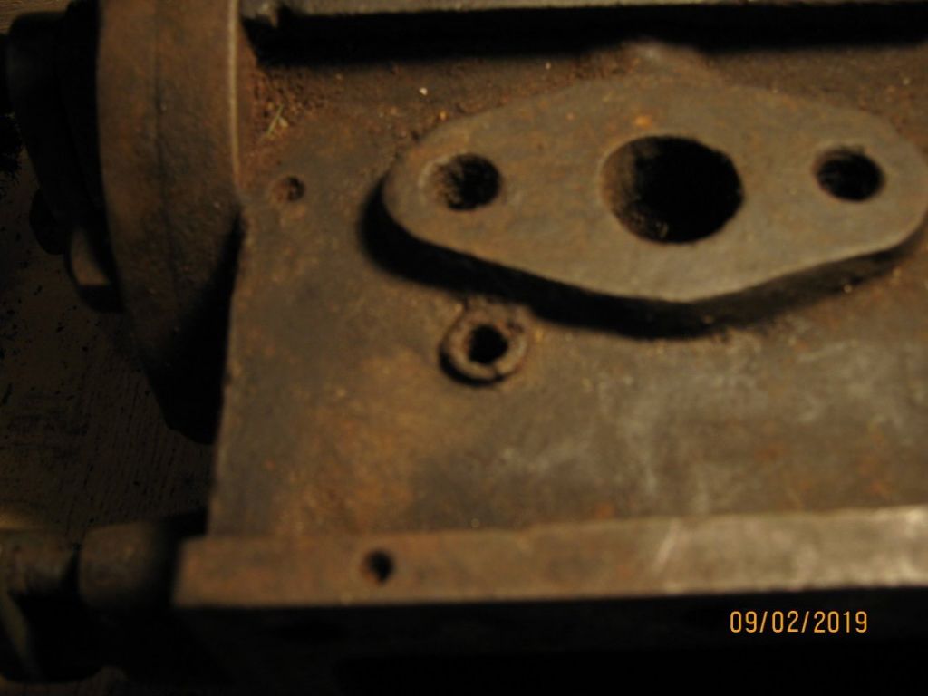
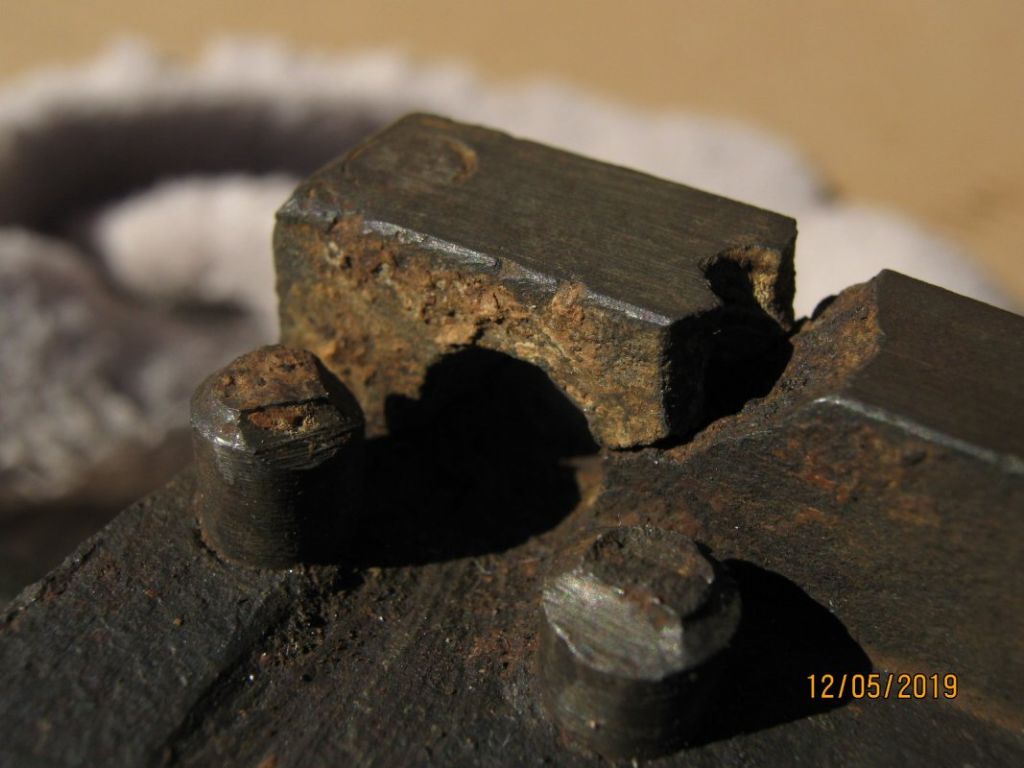
After initial clean up was able to further determine more detail. Much of the outwardly visible stuff was as expected, it was the other bits that came as a bit of a 'nasty'. This had probably sat around as 'no longer needed' in some works yard for ages and it would seem likely that at one stage some jolly fellow had decided to 'remove' all the brass fitting (like oilers etc.), but these had in most cases simply been broken off leaving that reminder firmly in the related thread hole (see typical pic below)! Still, I suppose they stopped the thread holes rusting away too much! There was a cracked corner of the steam chest cover mounting face on one cylinder.
 However, the fitting was still usable due to a clever (albeit crude) fix that someone had applied many years ago (see photo). They inserted 2 short studs behind the cracked corner and a new bolt head fitted behind these taking the pressure off the cracked portion,
the casting corner piece had a couple of fine screws holding it in place, but these had rusted to virtually nothing now so I eventually repaired in with a strong epoxy metal substitute.
Some other major points are as follows:
- The cylinder bores were not to bad and had a slight amount of wear as to be expected
- The piston rings were worn out totally and jammed tight in both the pistons, which were themselves loose on the shafts (holes enlarged, slightly oval) and unlikely to be re-usable..
- There was a slight difference internally between the two cylinders – the bore diameters were different by a couple of thou and the steam ports were closer to the ends in one compared to its 'twin'. Whether one had been replaced by an 'equivalent' at a different time or it was just the way things were made in those days is anyone’s guess – but it was going to require consideration if making replacement parts later!
- The centrifugal oiler rings for the big ends: One totally mangled the other damaged & loose with broken feed pipe. Both showed signs of attempts to crudely repair a few times, I would image a 'weakness' in the design.
Missing bits:
- No connecting rods.
- Only one valve mechanism – other totally missing. The complete one (although it’s eccentric shaft badly damaged) at least gave me a ‘pattern’.
- 1 Steam chest cover missing
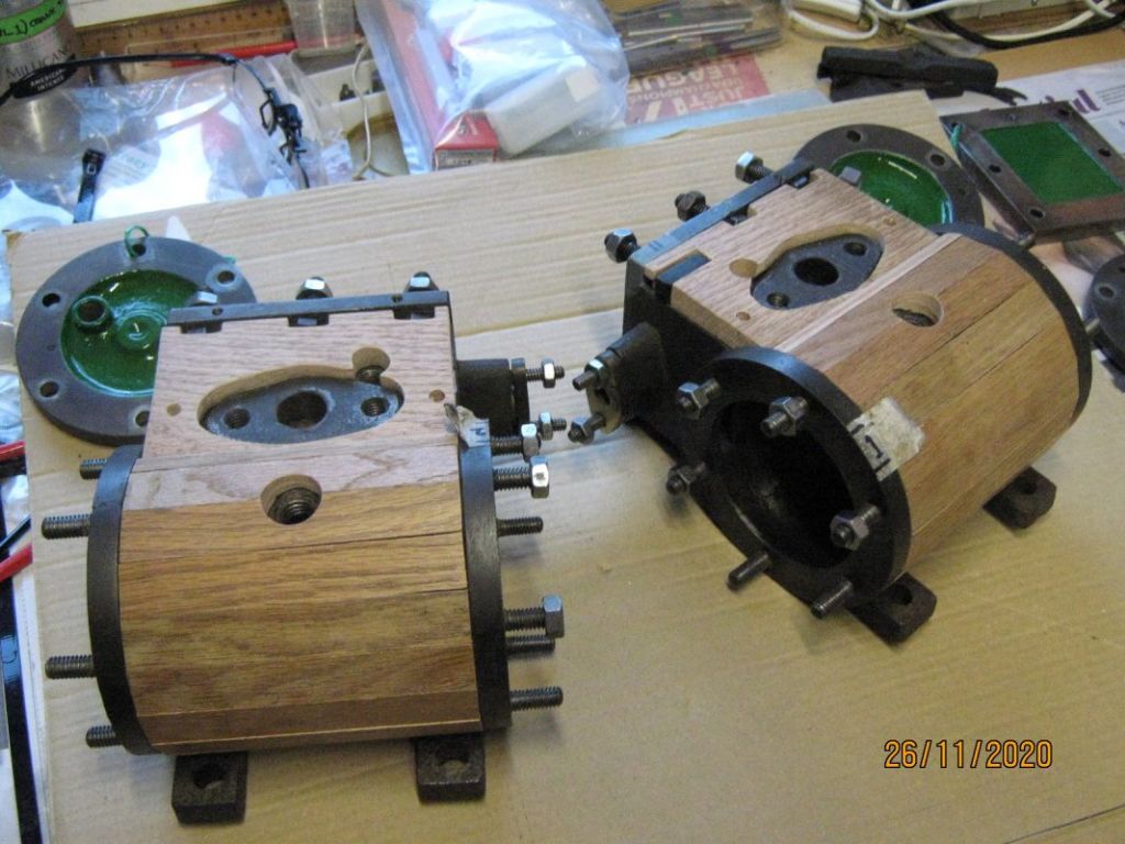
- No pipework, complete lagging, fittings etc. There were a couple of bits of wooden segment still whole that gave a useful insight into the cylinder lagging.
- No governor (assume it had one, although no sign of a fitting, bolt holes etc. but there is a small vee-belt type pulley on the main shaft and I can't think of any other purpose for it).
Unexpected problems found later on – LOTS!
Much later when doing initial alignment of parts, it became apparent the cranks weren't rotating correctly, this eventually was determined as due to a slightly bent main shaft! Oh joy!
The shaft seems quite light to me (3/4" dia) considering the weight of the flywheel, but had obviously worked OK for many years. The associated journal bearings looked in fine nick and fully reusable as they were.25 November 2020 at 09:39 #31328Mike Hurley
Participant@mikehurley60381On-going restoration of a 19th century engine.
25 November 2020 at 09:39 #509735Mike Hurley
Participant@mikehurley60381Anyway, all things considered I got on with it. Hopefully the photos and brief notes that will follow ( as time permits!) give an insight into the on-going project. Hope forum members find something of interest.
25 November 2020 at 10:12 #509743 JasonBModerator@jasonb
Look forward to the next instalments. Having seen the cylinder in your other thread it's nice to see the rest of the engine
25 November 2020 at 10:25 #509746Brian H
Participant@brianh50089Wonderful project, do you have any ideas as to what the engine was used for? Possibly driving some machinery?
Brian
25 November 2020 at 11:12 #509759ChrisH
Participant@chrishMichael – having interested me considerably with what you have written so far I went and looked at the photos in your album, and am now even more looking forward to the next instalments. Where you started from may well have put me off a bit, that poor engine was dire when you got it, well done you for not being phased by it and ploughing on with the reno.
Chris
25 November 2020 at 11:55 #509769Dave Wootton
Participant@davewoottonExcellent stuff Michael, a really interesting and worthwhile project that you are obviously doing to a high standard. Thanks for posting this I'll follow your progress with great interest.
Dave
25 November 2020 at 14:17 #509798Howard Lewis
Participant@howardlewis46836WHAT an improvement. From basket case to a well made working engine.
You are a man of vision, patience,persistence and skill!
Howard
26 November 2020 at 10:31 #509948Mike Hurley
Participant@mikehurley60381Thanks for all the encouraging comments. The best I ever get from the wife tends to be 'and what are you going to do with it when it's finished?…….', its cheered me up no end!
I don't consider myself particularly skilled, when compared to some of the guys in this forum for example, but I am dogged and prepared to learn as I go on. Make lots of mistakes in the process and know better next time. On reflection, it was a lot to take on in my mid 60's but, its kept me busy and mentally stimulated – particularly as things turned out during the grim year were in!
I'll be posting more details shortly.
Regards to all, keep well Mike
28 November 2020 at 12:34 #510397Mike Hurley
Participant@mikehurley60381Brian H – No idea I’m afraid as I don’t know where it worked. Typically I believe these engines were just a ‘utility’ power source and used for small workshops and even agricultural use. The flat pulley would be typically driving a flat belt to a line-shaft to power 1 or more machines.
The key restoration steps were initially determined to be: (the order is not cast in stone though)
- De-grot everything (large amounts of thinners used – out of doors), remove as much rust as possible, clean all orifices.
- Remove numerous broken parts in thread holes, avoiding excessive bad language for sake of neighbours, check viability of threads.
- Determine which bits will definitely need replacing, make materials list.
- Start a written notes log as useful reference later (turned out to be a really good idea!)
Start cutting metal!:
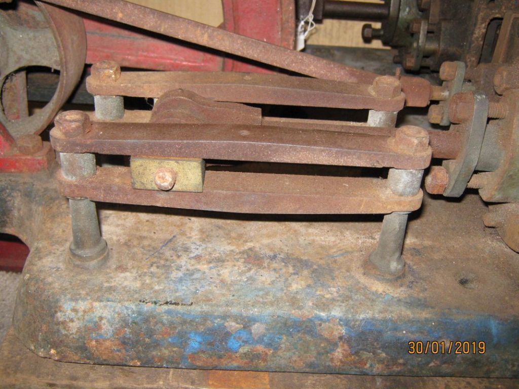
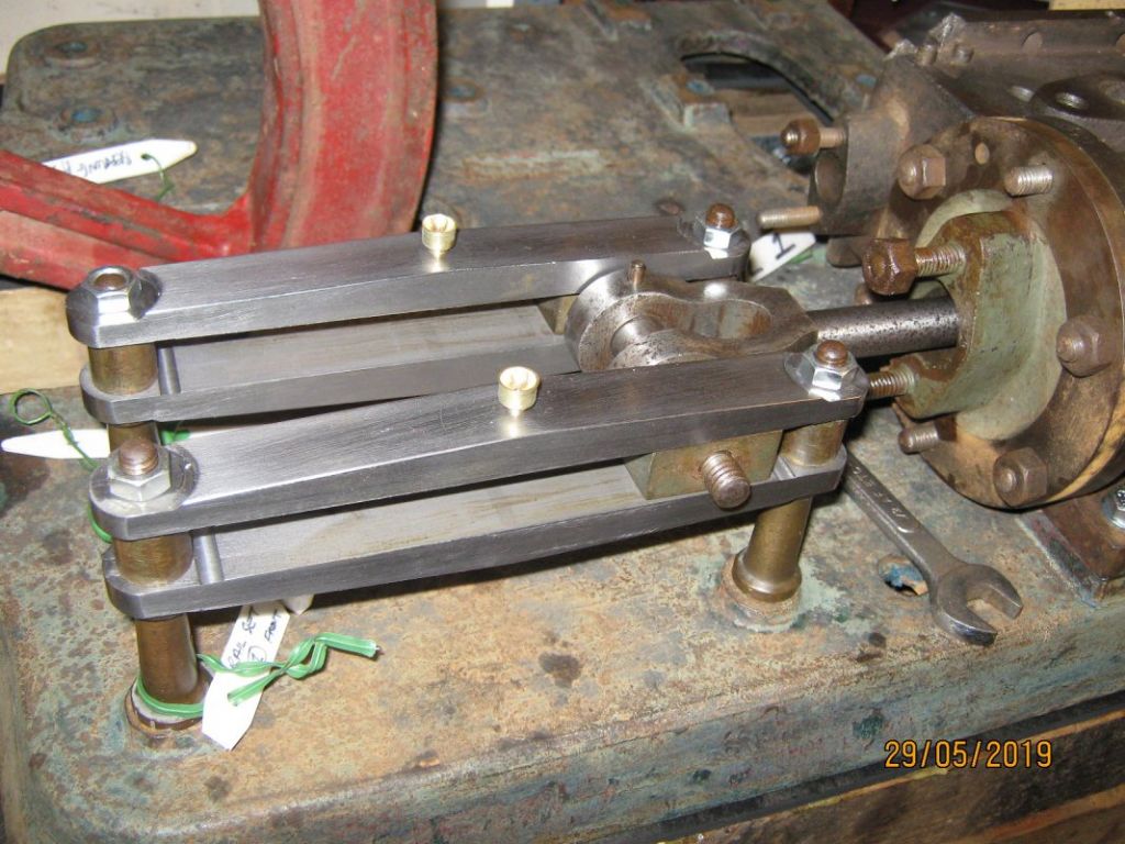
The X-head slide rails were very badly corroded and needed replacing. The damage was so severe that I could only get a general sense of the actual dimensions, but would be sufficient. The rails were mounted each on 2 brass pillars with spacers between, these located into the base casting via loose studs (badly rusted).Shaped up 4 bars on the Mill, milled narrow oil channels and lapped the running faces. Fitted small brass oil cups
to upper rails. Quite some time taken up getting the initial fit right (new studs had to be made, a couple of pillars / spacers replaced as damaged).
Test fitting the X-head bearings (which were in fine condition) showed manual adjustment required, so I made a
selection of brass shim washers 2,4,10 thou. Worked well and initial setup seemed OK. Will obviously need final adjustment much later.PISTONS next. The pistons themselves were unfortunately beyond redemption . The piston rods weren’t too bad but lightly pitted. They cleaned up OK – not ideal – but I though reasonable and as mentioned earlier I wanted to try and retain as many original parts as poss. if still serviceable in any way.
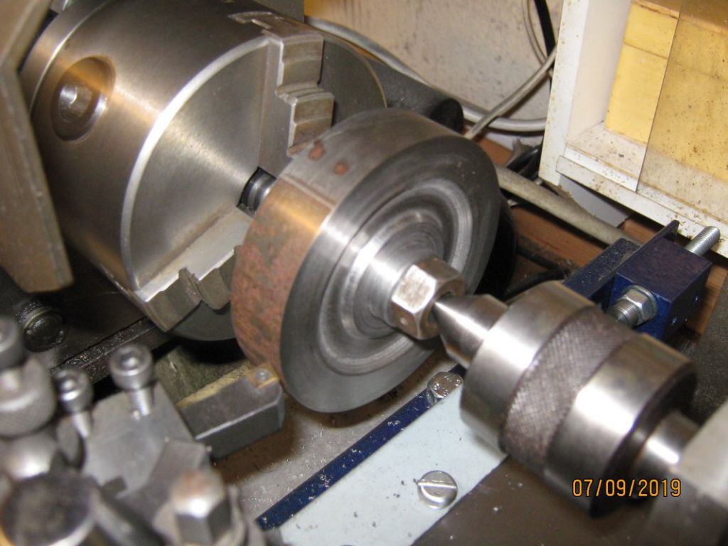
Routine turning job really. Custom mandrels, do all without removing to retain trueness etc.
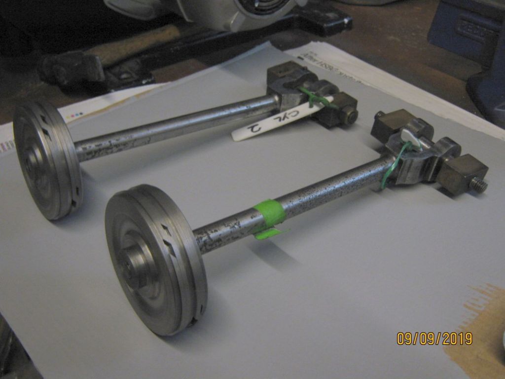
CI is nice stuff to turn when you get under the hard outer skin isn’t it? Bit mucky though. Ring grooves cut with a ‘Q-Cut’ parting tool / depth stop on cross slide. Clupet type rings (bought in I admit) fitted and unit attached to rods and test fitted in cylinders (which I had thoroughly honed previously). Fairly happy.CONNECTING RODS.
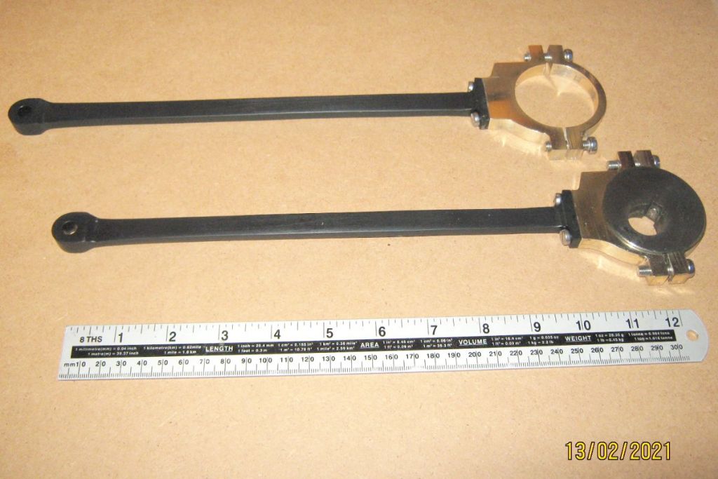
A toughy this as I had nothing to go on as both were missing. Spent many happy hours examining photos on old engines and similar documents. Arrived at a general concept that I thought would fit the bill. Sketch made and then needed dimensions. The critical one being the distance between centres of the big and small ends. Rather than try to
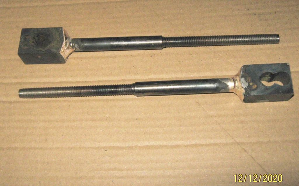
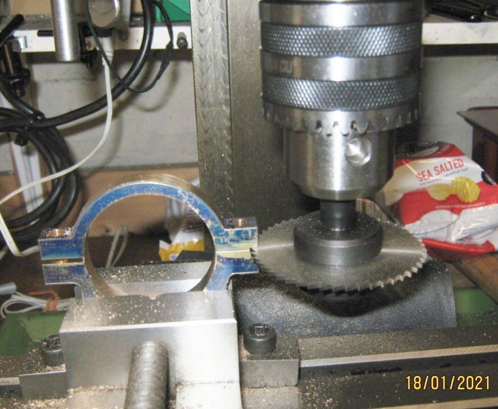
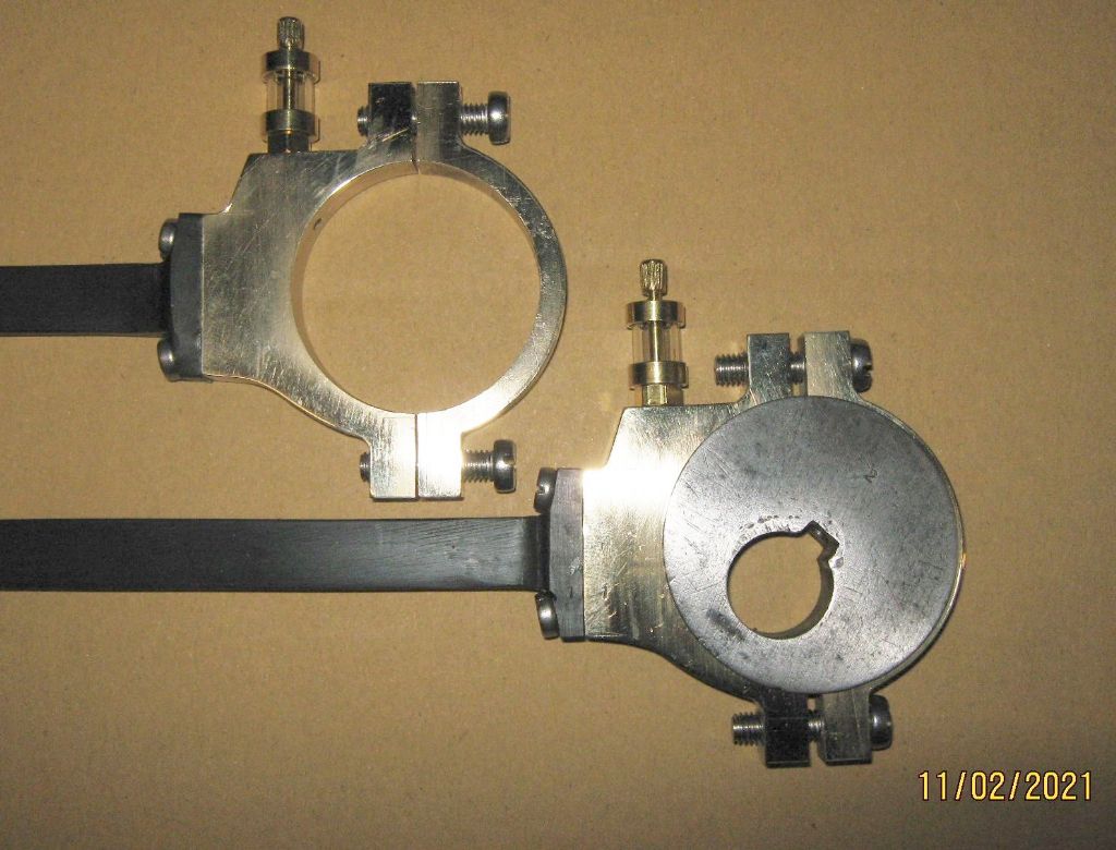
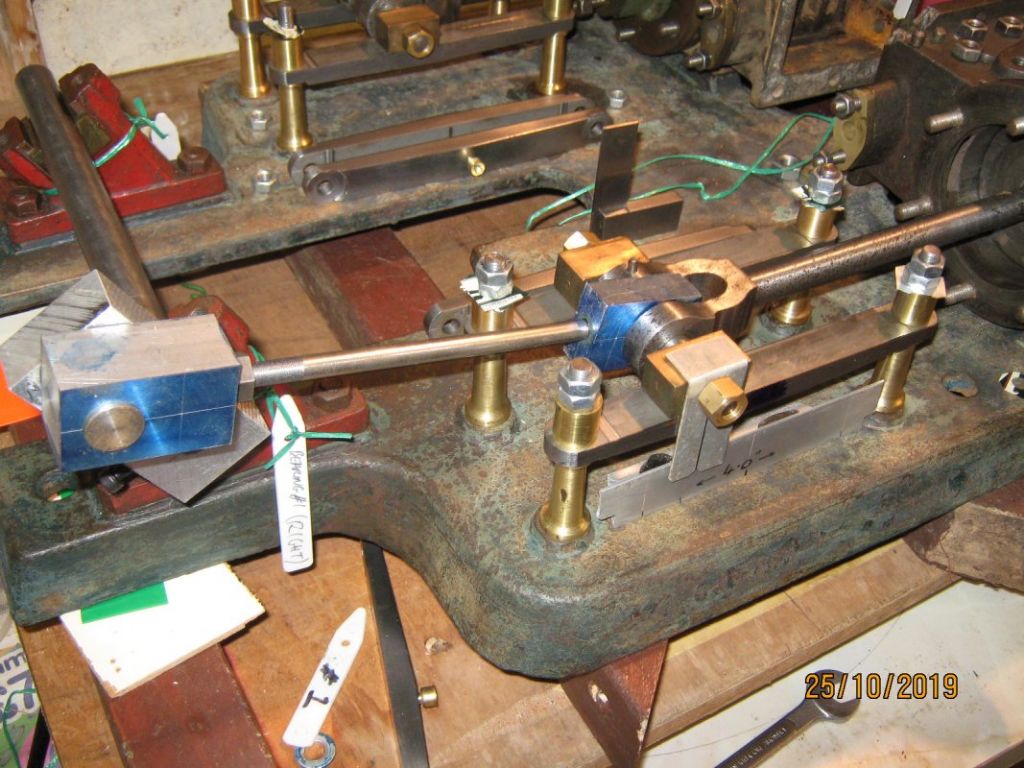
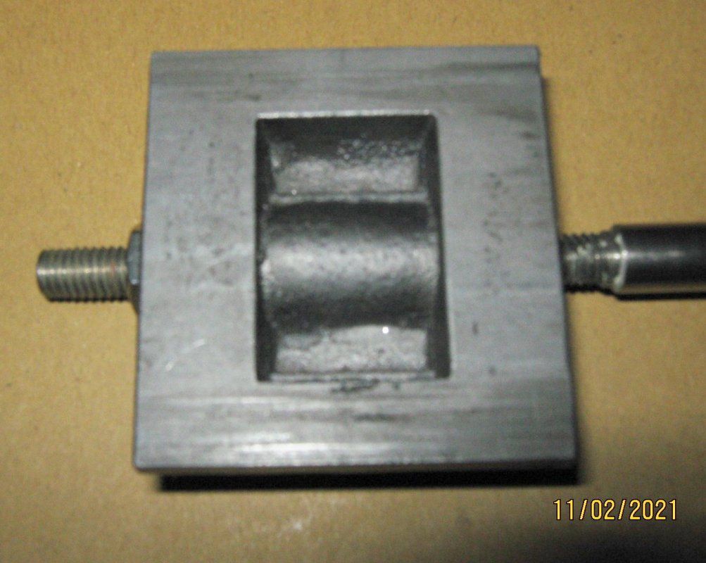
‘theorise’ or guess/measure this I decided to make an adjustable gauge of 2 aluminium blocks bored to the correct
dias. of the (temporary test) crank pin and X-head shaft on a shaft with fine threads at each end allowing precise length adjustment. This proved invaluable, as you could ‘dry-run’ the complete set up manually ensuring the correct travel of the X-heads and that the pistons were clearing the steam ports correctly. After many hours of fiddling, I came to a dimension of 204mm (8.0in. near as) Which seemed totally logical for the period! So I felt comfortable I was right. I’m sure our Victorian engineering forefathers probably measured all this with a bit of knotted string and charcoal and still got it absolutely spot on!Drew everything up (on real paper with a pencil & ruler!) yes, I know CAD is brilliant for this sort of stuff, but I honestly find that for a one-off like this the old ‘technical drawing’ skills are quicker and more easily modified.
Some may disagree – it’s personal choice at the end I suppose.Be posting continuation details shortly.
Regards to all, keep well. Mike
2 December 2020 at 16:34 #511237Mike Hurley
Participant@mikehurley60381Once decided on, pondered how to actually do it! May not have been the best way in the end but essentially consisted of –
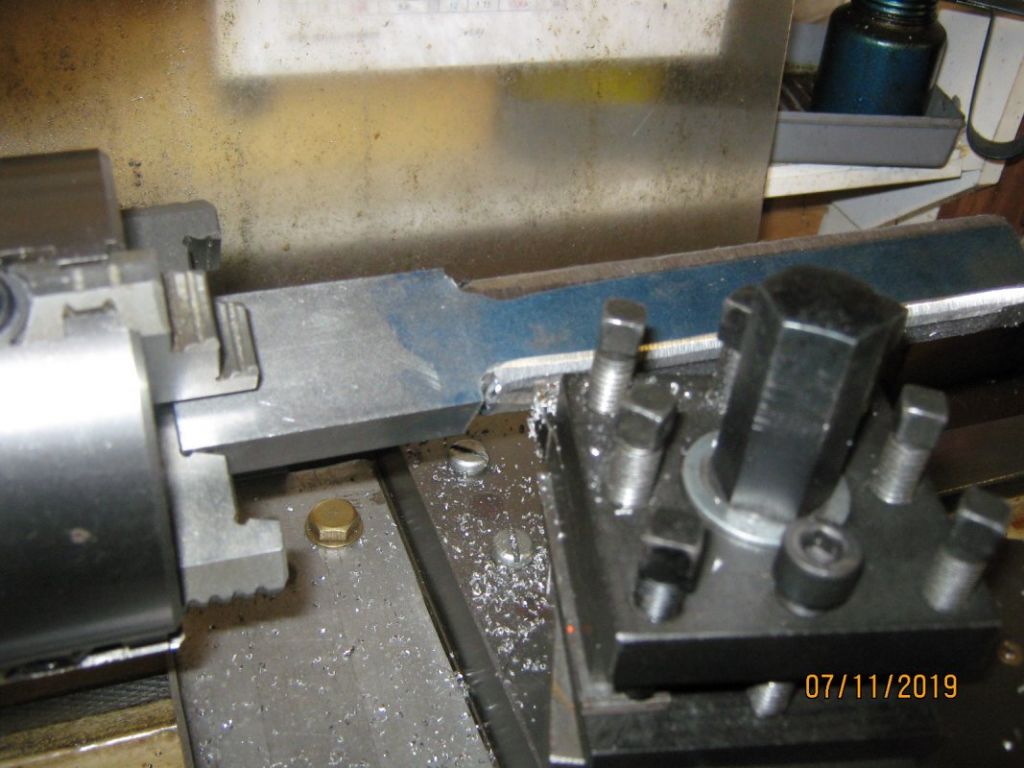
Cut a piece of 1 1/4“ x 3/4“ bar to length + bit spare, manually drill centres both ends. Using an angle grinder, reduce
the centre section while rounding off the corners as much as possible (I haven’t got a metal cutting band saw) so you
end up with a sort of elongated ‘H’ shape.
Mount between centres with a ‘custom’ drive dog, reduce centre section to a cylinder on both pieces. (Found that the
intermittent cutting kept loosening my QC tool holder because of vibration, so changed to traditional one.)

Once all round, offset tailstock and turned slight taper towards centre. Reverse work and repeat. Manually reduce
the ‘peak’ in the middle (file) to give a more aesthetic shape. Polish.Boring the big and small ends were again fairly routine jobs in the mill I won’t bother to detail here. As with
most jobs like this, most time taken in the fixing (due to the awkward shape) and accurate setting up.Job not helped by the mill’s motor deciding to die in the middle of the work!
Now £100+ lighter ………. To continue——-
Bearings. Small end P/Bronze, a tight press fit, with simple oiler hole. Big end – split. Viewed articles on this
site and elsewhere and all seemed to have good and bad points on methods so I picked those ideas that I thought
would work and went ahead. It will either do the job or not! Learn as you go along – just a pity PB is so expensive
if you happen to screw it up!.
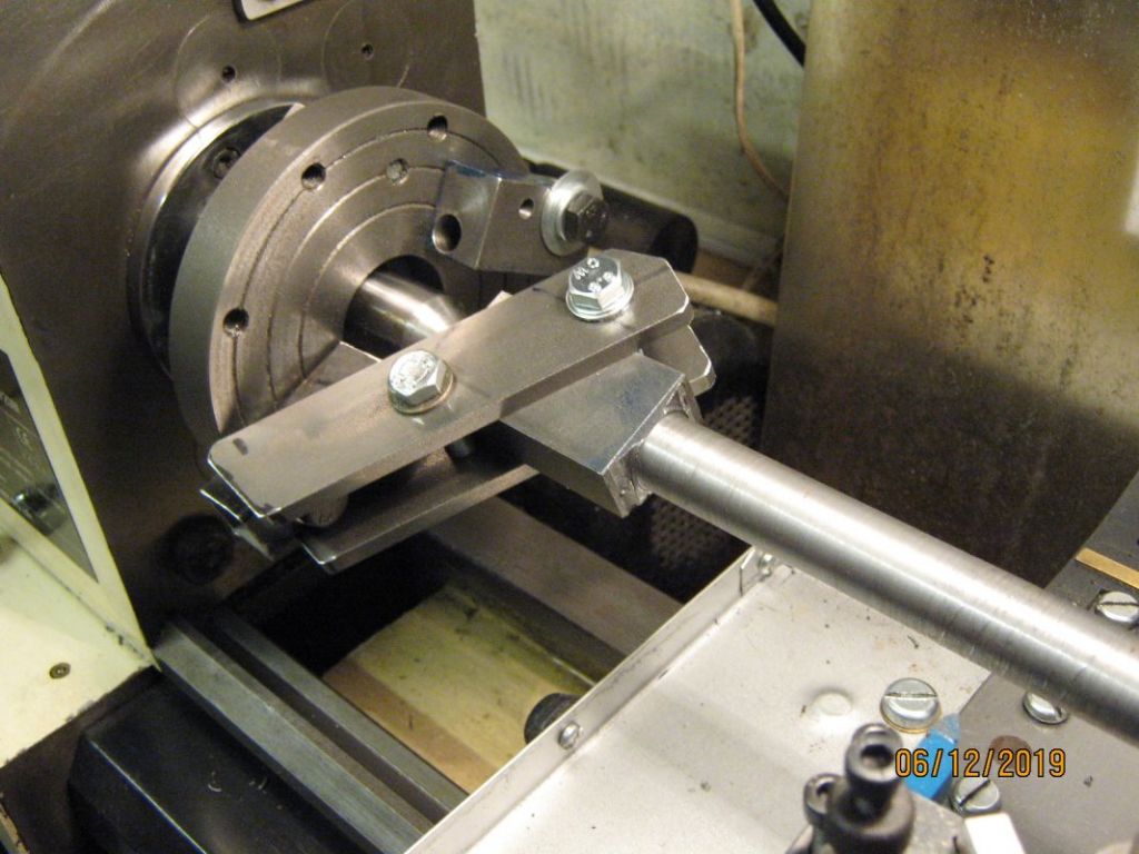
Lathe didn’t have the swing to permit boring the split bearings in situ on the conn rods, so made an accurate
aluminium jig that bolted to the faceplate.Worked very well and provided a nice accurate pair of bearings.

So far so good. (oh the foolish boy!… should have known better.)
Test set up.
Fitted the real main shaft (mighty weighty to heave on & off with its CI 18" dia flywheel plus pulley – hence
the temporary use of a ‘test shaft). In essence, nothing lined up. After much investigation it was determined
that both crank pins were a wee bit out of true, (but couldn’t easily determine by how much while in situ.) A dial gauge ‘lash up’ indicated that the main shaft was also slightly out of true. It was going to be a total strip down & re-build job by the look of it.
Everything was totally solid! Each crank was located by a hefty taper pin and also had short taper pins flush in
the ends (as keys). Just could not remove the cranks – tried every method known to man. They were made to stay in place….
Only remedy was to cut the shaft (was needing to be replaced anyway), then drill out the remnants. Took fastidious
detailed measurements and extra photos first – then out came the hacksaw.Flywheel, pulley and eccentrics were all held in place with keys locating on flats machined on the shaft. Hammer & drifts soon loosened these.
After drilling and applying brute force, managed to remove the cranks, each one had 3 small taper pins (all
different sizes of course), the holes (like a keyway) ½ in the crank, and ½ in the shaft. I think the apprentice who
drilled these must have either been VERY bad at his job, or inebriated as none were straight.

If I was to retain the cranks but machine a new shaft – that would have to have ‘matching’ misaligned taper holes.
That was going to be fun! More on that later.7 December 2020 at 10:13 #512106Mike Hurley
Participant@mikehurley60381CRANKS
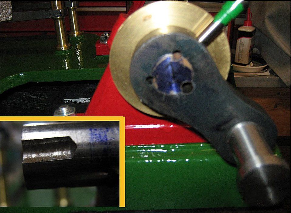
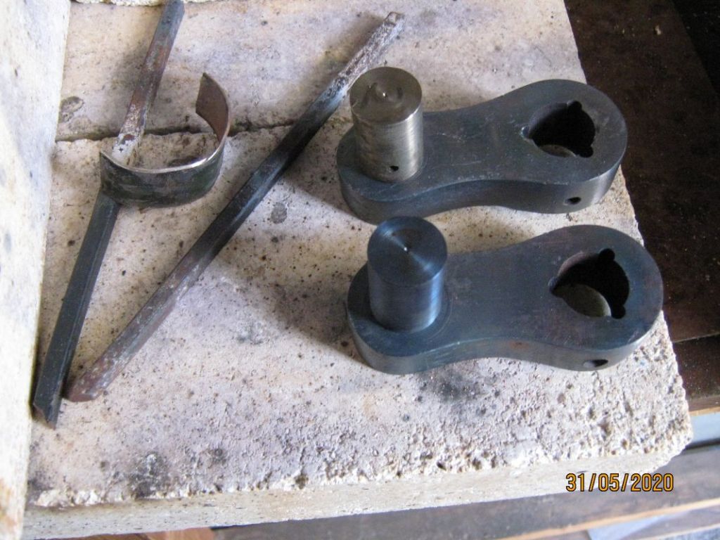
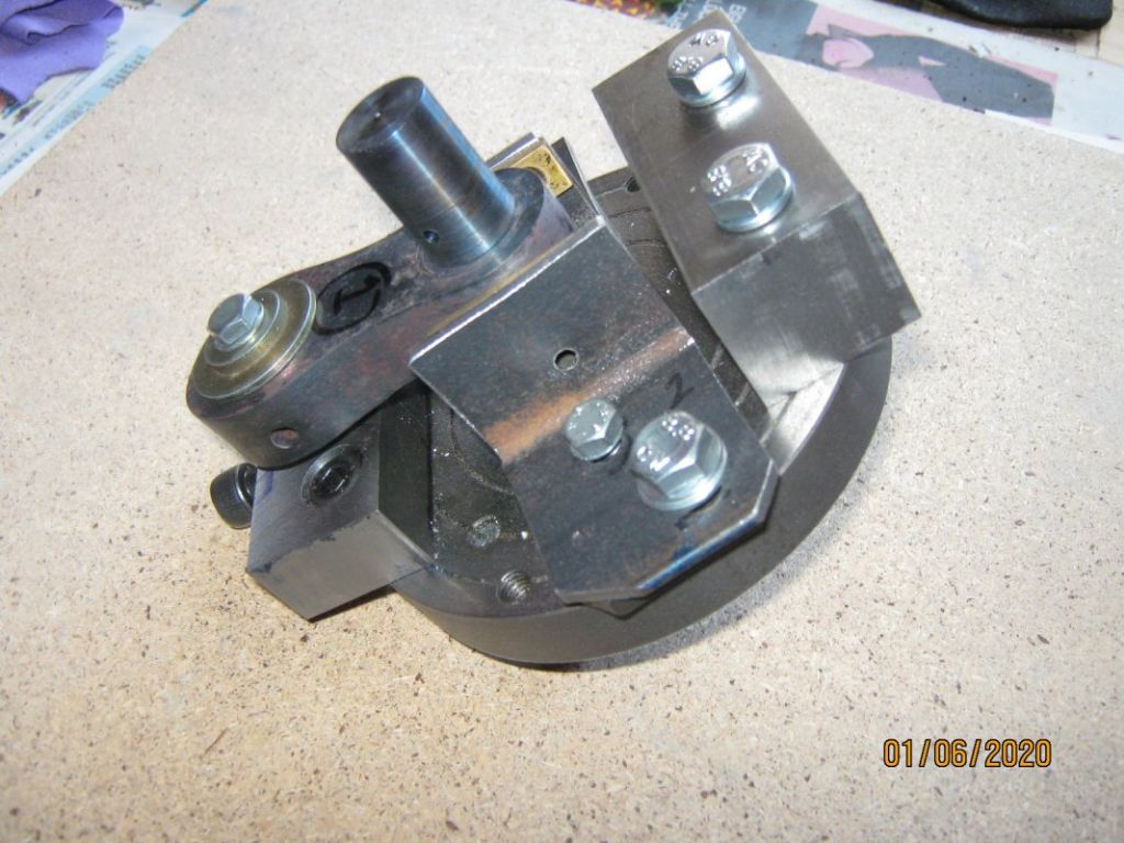
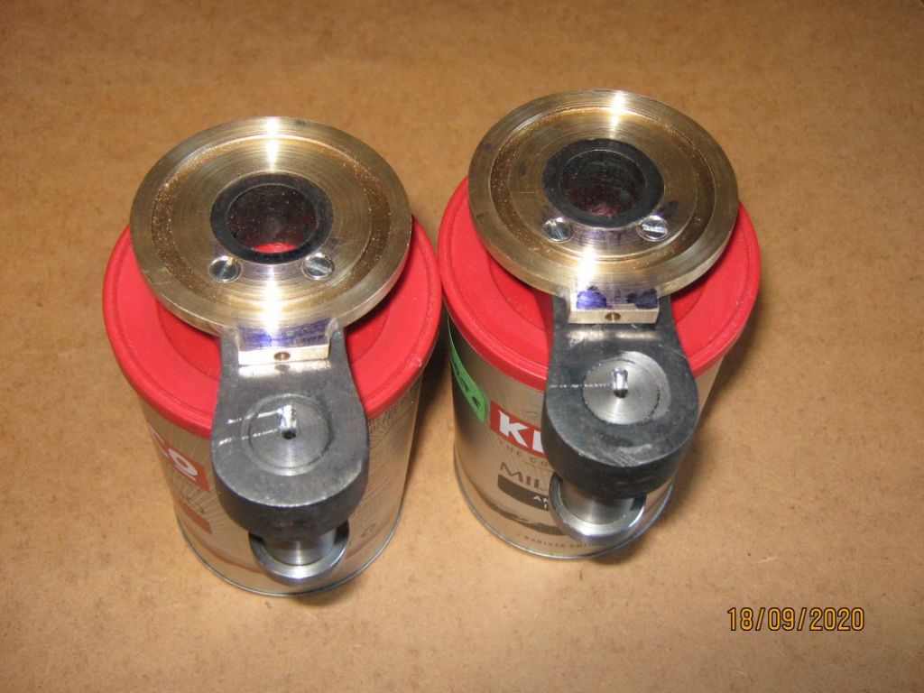
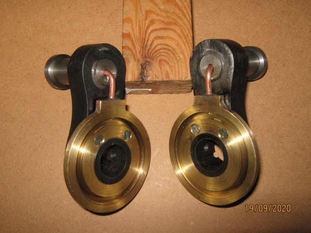
The crank pins were both out of true, plus the attached centrifugal oilers were beyond repair. I wanted to save the original cranks themselves, but it would be necessary to replace the pins. It was found that the originals were screwed in and the rear edge peened over to retain them. They were removed. A faceplate jig was fabricated that centered the hole for the new pins – these had a 2" throw from the centre of where the main shaft would be. A short mandrel substituted for the shaft.The holes were bored and new oversized pins turned, these were then heat shrunk in place.

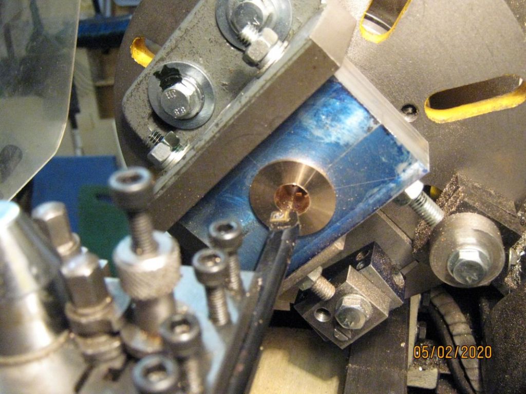
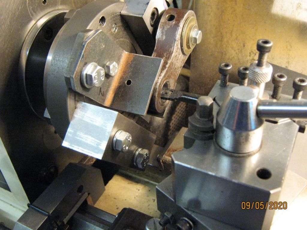
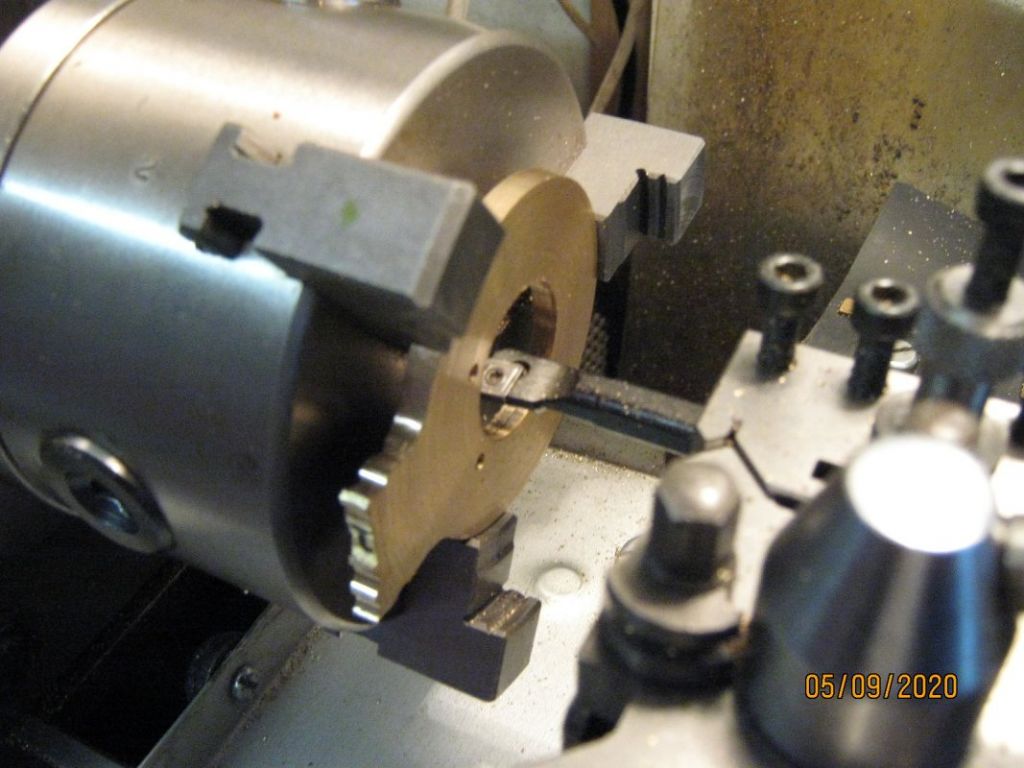
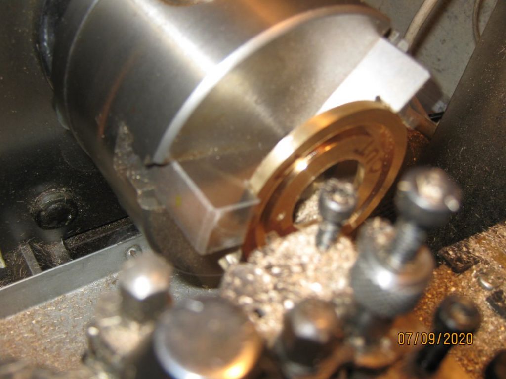
The jig was now utilised to accurately turn the pins to final size in line with the main shaft.The cranks originally had brass centrifugal oilers fitted. These consisted of brass disks about 8mm thick with a recessed channel all around. An 1/8" brass pipe was soldered into this and then ran up to an oil channel drilled into the crank pin. These had obviously been a weak point as what remained showed repeated signs of repair. I decided that in making replacements I would attempt to strengthen this junction. As you will see in photos later, this is what I did – although it meant I couldn't turn the outer shape directly on the lathe but had to use the mill + rotary table.
Once to shape, set in the 4-jaw to bore the centre hole (could have done this whilst still on the mill, but they needed to go in the lathe later anyway to bore the oil channels)Took much longer, but proved to be worthwhile in my opinion. The pictures show the job fairly clearly, was quite challenging to undercut the channel on a relatively narrow section as my scrap box bears witness to! I still have absolutely no idea of the original set up to apply oil into this arrangement as no parts remain. It must have been either some type of wick/drip oiler or a small pipe feeding directly from a reservoir or something? If anyone has any suggestions I would be most grateful to hear them!
More to follow as time permits… Mike
7 December 2020 at 17:34 #512216David Roberts 21
Participant@davidroberts21Hi Mike,
keep up the good work. I have a similar engine that has been modified to a vertical position, with a SLRG to boot.
it was installed in GLENROSA , a 35 ft `steam launch with a low moor wrought iron hull of 1870 vintage. The hull was salvaged from a farm where it served for over 49 years as a water trough for the cattle. The launch has been converted to electric, commonly used from 1890 on. I have owned THAMES ESPERANZA, 1898 , a 52ft steam cabin launch on the Thames that was originally electricity powered.
I will venture to my barn and photograph it in the morning.
ceers
Dave
13 December 2020 at 10:52 #513226Mike Hurley
Participant@mikehurley60381Sounds most interesting Dave, I'd love to see a photo. When you say 'similar', any details? (bore / stroke etc) because any little snippets of info might be useful as I'm struggling in several areas with lack of info.
Regards.
13 December 2020 at 11:09 #513227Mike Hurley
Participant@mikehurley60381NEW MAIN SHAFT
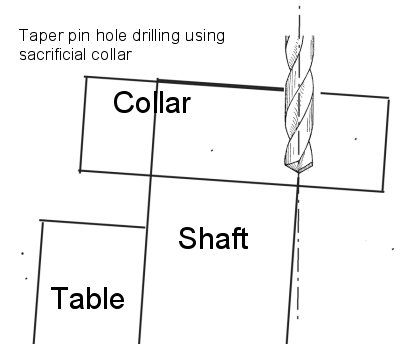
The basic shaft was a straightforward between-centres turning job. Later operations would involve cutting 'keyway' flats and taper holes.As best I could determine, the 'driving' pins (round taper keys in the ends of the shaft that locate into the crank bore) were standard imperial 1:48 taper. Not having a variety of taper drills to match the short holes I had to devise a way to drill them. As I had retained the parts of the old shaft I was able to measure the length and degree of misalignment.
After the new shaft had been turned to size I mounted it vertically in the drill press having a tightly fitting sacrificial 'collar' fitted (i.e. where the crank would be) then tilted the whole thing in 2 axis – 1 to give the 'effective' taper and 2. to match the misalignment. Not surprisingly there was a lot of bad language during this exercise and, as usually happens, after 30mins of setting up that last gentle tap overdoes it and you're back to square one. I Drill down each one with appropriate standard drill, reverse and repeat for the other end of the shaft.Although time consuming and often frustrating it all worked out quite well!
The main locating taper pins (at right angles to the shaft) were quite sturdy pieces, but had worn quite badly – the holes in both the shaft and both cranks being different sizes (how unusual!) and slightly oval. From what I could measure of the existing pins, they were not 1:48 taper, more like about 1:32! so I assume they were just one off items made specially for the job.
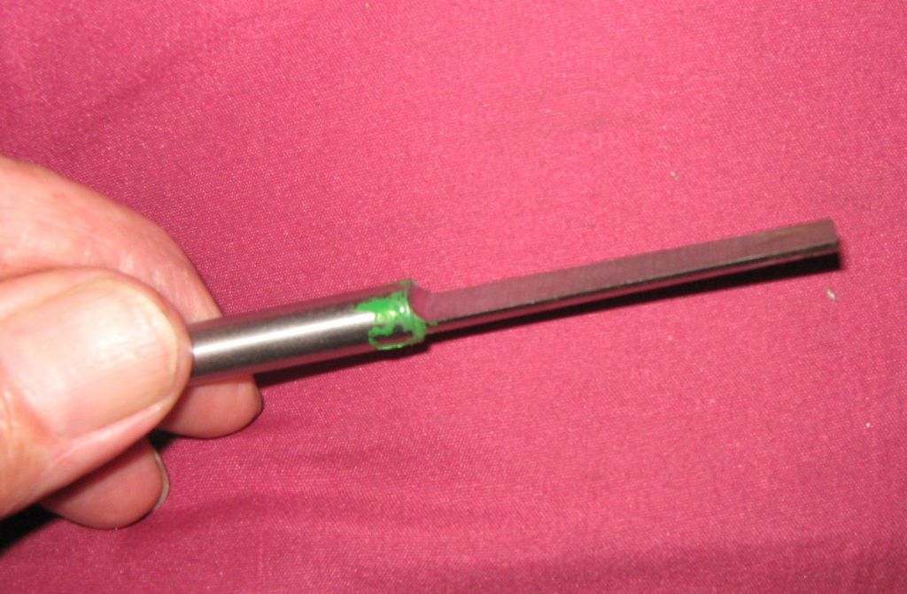
With all the issues, it was sensible to make two new taper holes (was going to need to do this in the new shaft anyway) that 'fitted' the holes in the cranks as they were. These were made up from silver steel bar (simple single flute type, like a D-bit) hardened & tempered etc.Drilled the stepped through hole through the assemblies and then reamed – was surprised how well they cut for a simple tool.
Because one side had worn more than the other the final tapers used were slightly different, so needed 'custom' taper pins for each side. Not ideal, and on reflection I might have tried to get both the same, but in practice these are unlikely to ever need to come out again once fitted.
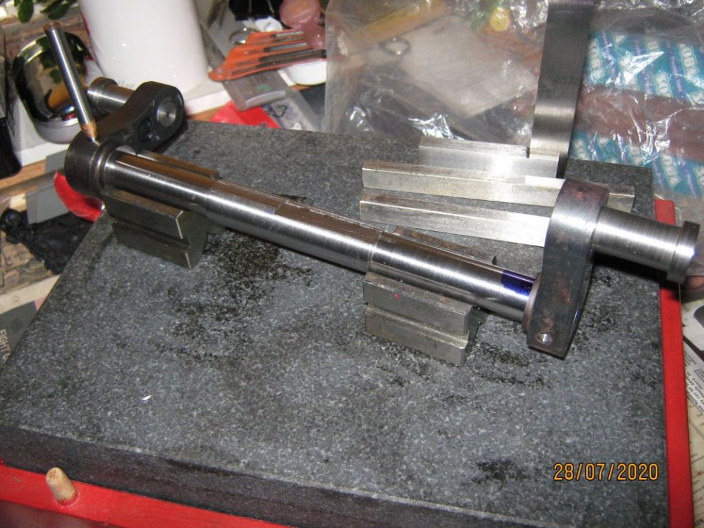
Last job on the shaft was to machine the flats for the various keys (Flywheel, Puller, valve eccentric). Sensibly I had made very accurate measurements of all the parameters before butchering the original shaft, however, as belt-and-braces I did (using the pieces I retained) double check the angle between the cranks and flats for the valve eccentrics.It ended up being a relatively straightforward job using the rotary table on the mill and final result was good. (Photo shows temporary over-long taper pins fitted).
Temporarily put to one side now until the main re-assembly starts. Have since been involved on a number of the 100 + 1 more 'minor' bits and pieces (including painting where required) and cutting the laths for the cylinder lagging.
I knew that this was how it was originally because, although both cylinders were pretty much 'naked', there did remain a couple of very old blackened pieces of wood under the bottom of one, this giving me as approximate size and profile for me to use. Fortunately I had a piece of well seasoned oak that turned out to fit the bill – a real stroke of luck!The location of a number of 3/16" screw thread holes in the castings gave me an idea of how & where the banding would be fitted to hold these segmants in situ. However a degree of guesswork will be involved I suppose. I will base the final assembly on similar configurations seen in pictures of many various engines of the period.
Currently I'm attacking the valve mechanisms. This is going to be quite involved as the few original parts that remain were in a very bad state. Probably 70 – 80% will need to be replaced. So probably no updates for a while (anyway with Christmas pending and the chilly winter-time workshop, progress tends to be a bit slow and erratic at present!
Seasons greetings to all, hope Santa brings you lots of new shiny tools and fingers crossed that 2021 will be a bit kinder to everyone! Mike14 December 2020 at 23:12 #513542
David Roberts 21
Participant@davidroberts21Hi Mike,
how does one send a photo on this site. The icons above are unhelpful, but the answer is lurking in there .
Dave^
15 December 2020 at 06:59 #513551 JasonBModerator@jasonb15 December 2020 at 09:46 #513576
SillyOldDuffer
Moderator@sillyolddufferSomehow I missed all Mike's earlier updates on this engine restoration. Perhaps stunned silence is the fate of threads like this! Finding it cheered me up no end over this morning's coffee.
Thanks for sharing Mike – impressive work, and so quick. (I once spent a whole day struggling to cut a satisfactory slot in a screw-head!)
Dave
15 December 2020 at 10:17 #513594Mike Hurley
Participant@mikehurley60381Not that quick I'm afraid Dave! Much of the text and photos are retrospective as I've been working on this since early 2019, but did take load of piccies at the time jobs were in hand and keep a detailed log for ny own interest, I only fairly recently joined this forum and then thought this stuff might be of interest to others, so collated it and posted it in 'chunks' as I strung it together.
Initially I was a bit aprehensive about putting my 'efforts' up with such a band of experienced and talented people on board the forum! But from what I could see the general tone always seems to be much more helpful and supportive to people than critical so decided to give it a go.
Glad you enjoyed reading it – thats always encouraging!. Mike
2 January 2021 at 22:21 #517112David Roberts 21
Participant@davidroberts21Hi Mike,
im a dummy when it comes to downloading, cut and paste, etc.
I have a few shots of my twin HP for you. E mail me on daveroberts.redlodge@gmail.com and I will send them.
you are welcome to post them , and I can take more when I can extract them. I need a strong lad to move them
to a better site.
Dave
2 January 2021 at 23:16 #517125Nigel Graham 2
Participant@nigelgraham2A fine project, Mike, with a lot of intriguing design and machining problems to solve.
Is there no sign of a maker's name anywhere? There were any number of small engineering firms making versatile utility engines like these. Few had reversing-gear as it was not normally needed, but some were fitted with slotted eccentric sheaves so the engine could be set in either direction to suit whatever plant it was driving.
Thank you showing us!
10 March 2021 at 11:40 #532962Mike Hurley
Participant@mikehurley60381Sorry for the delay in responding, I just hadn't looked at the posing until recently as I didn't have any updates for it.I've been doing some work and was about to update it and realise there were one or two posts 'outstanding', so apologies again.No makers name (one of the first things I looked for!) unfortunately, and I have tried (believe me I have tried!) to find an image or info anywhere that gives a clue to its exact age and birthplace without luck. It seems pretty basic in construct and limited features, which leads me to think that it is quite early. Anyway, hope you find the following update on progress of interest. regards, Mike10 March 2021 at 12:01 #532969Mike Hurley
Participant@mikehurley60381VALVE MECHANISMS
4 main parts to deal with.- Eccentrics on main shaft
- The D valves themtselves
- The adjustable shafts
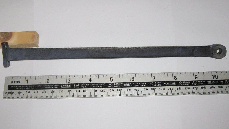
- Connecting rods – Connects eccentrics to adjustable shafts.
As noted earlier, few original parts that remain were in a very bad state and these were off one side only, so a complete set will have to be made for the second cylinder anyway. The eccentric on main shaft had been damaged and MAY be repairable but that has to be seen. The connecting rod was a fairly basic forged unit, but was badly bent and corroded. The threaded shaft similar. The D valve is a single CI casting, worn and corroded.
Much earlier in the restoration process, I had been aware of these issues so took steps to look into getting things moving on bits I couldn't easily do myself. Struggled for ages to find a 'proper' blacksmith to forge the connecting rods but finally got someone who came up with the goods at a reasonable price, they are rough and ready so will need cleaning up and machining to size etc.The D valves were sourced from Oak castings who were excellent to deal with and did a fine job.
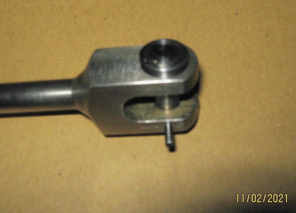
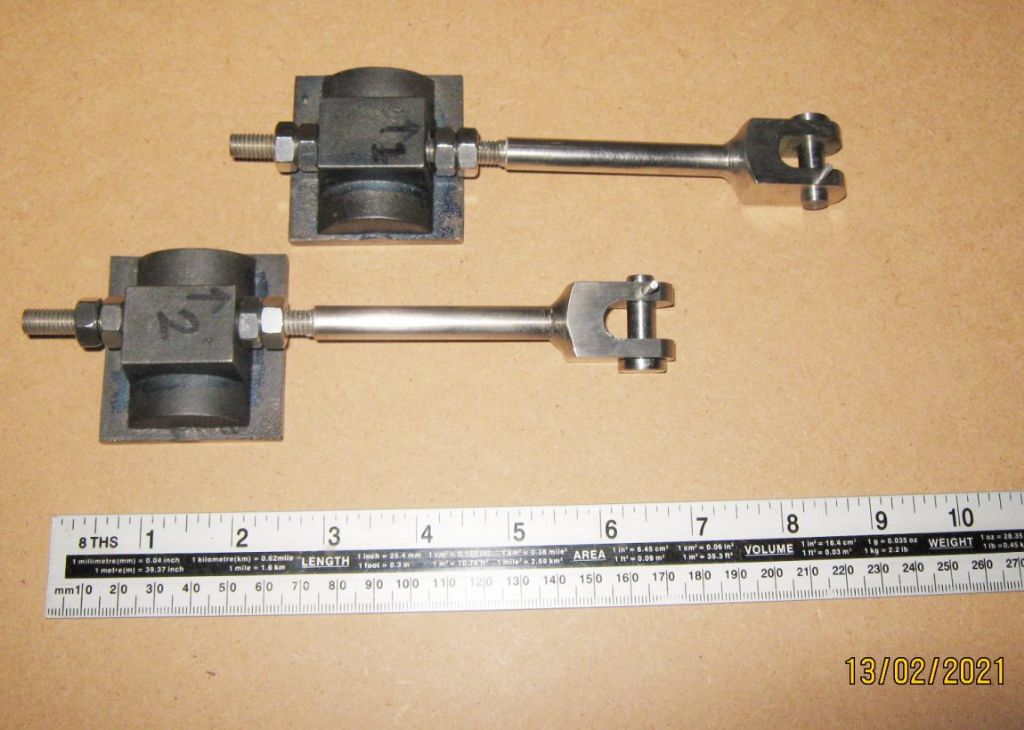
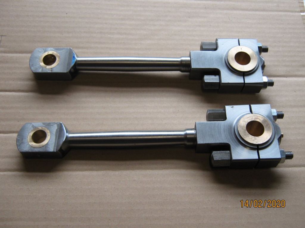
The adjustable shaft has a length of thread that fits through a hole slightly larger in the D Valve and each has 2 pairs of brass nuts holding it in position (so the D valve has a degree of free 'float'
 . The other end is a fork with an 5/16" pin (held by a small taper pin) that connects to the small end of the connecting rod.
The original would have been in one piece either forged then machined, or machined from solid. Due to equipment limitations, I made each in 2 parts making the forked end from square stock and the shaft from 3/8" bar, then silver soldering together. Appeared to work well, then completing the final machining after assembly to ensure correct alignment.

I had noticed that the original shaft had a coating of some kind, but suspect it was possibly there to inhibit corrosion, as the inside of the steam chest would be a pretty 'hostile' environment for steel? So am considering attempting home nickel electroplating – checked out a few 'YouTube' videos and it looks relatively straightforward – we shall see!************
Since the weather warmed up a bit, and Xmas was out of the way. managed to get on with all the above. Everything pretty straightforward so I shan't detail it in text, just added a few photos.
D valve castings machined, shaft plated and assembled successfully
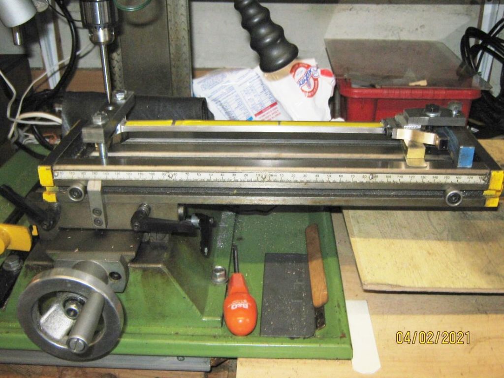
Aligning link shaft for eccentric (Mill table only just long enough!)
Splitting the Eccentrics after turning / milling in one piece each

Shafts + Eccentrics fixed together

Oilways were machined in the eccentrics and small drip feed oilers sourced and fitted

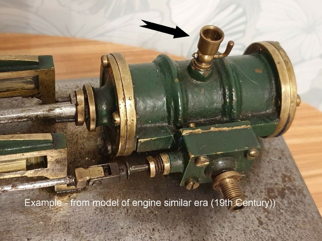
Made a temporary fitting for the top of the cylinders – When I received the engine and did the check of what issues there were, one of the points I noted was that there was the broken remains of a threaded 'something' in the top of both cylinders. As mentioned at the beginning of this article, any valuable 'brass' parts seem to have been rather brutally robbed off the carcase many years ago! No idea originally what they were but subsequent investigation leads me to belive they are in fact the remains of manual oilers which were typical in very early engines. I (eventually) managed to get the remains out and determined they were a 1/2" x 12TPI Whit thread.
Here's an example from a model of an engine from the same era that I believe will be a suitable style.
 10 March 2021 at 12:02 #532970
Mike Hurley
Participant@mikehurley60381[Had to split posting as to many characters]
I shall eventually make something like these, but for the moment I've just created a couple of brass threaded plugs that have a through threaded hole for manual oiling (closed by a bolt afterwards), this will be adequate for a short testing phase. Have also knocked up various gaskets, brass straps for the wooden lagging on the cylinders and some initial 'stub' exhaust pipes.
It's now getting to the point of starting to re-assemble everything! Oh the excitement!! ( well at least until I find that nothing I've made fits properly). Will update on progress.10 March 2021 at 12:22 #532973 Jim NicParticipant@jimnic
Just read this through for the first time, I don't know how I missed it earlier.
A wonderful project and some great work in getting it back to a great state, well done.
Jim
-
AuthorPosts
- Please log in to reply to this topic. Registering is free and easy using the links on the menu at the top of this page.
Latest Replies
Home › Forums › Work In Progress and completed items › Topics
-
- Topic
- Voices
- Posts
- Last Post
-
-
Wyvern Engine
Started by:
Dave C in: Help and Assistance! (Offered or Wanted)
- 6
- 10
-
23 May 2025 at 11:54
Dave C
-
Which to buy; Warco GH Universal vs Weiss VM32H Mill
Started by:
thisdesignedthat in: Manual machine tools
- 6
- 9
-
23 May 2025 at 11:52
thisdesignedthat
-
Is a tool & cutter grinder worth having?
1
2
3
Started by:
Brian H in: General Questions
- 40
- 60
-
23 May 2025 at 11:48
Howard Lewis
-
Hints and tips
Started by:
larry phelan 1 in: Hints And Tips for model engineers
- 2
- 2
-
23 May 2025 at 11:16
 Michael Gilligan
-
2inch Fowler plans
Started by:
bob53page in: Traction engines
- 4
- 4
-
23 May 2025 at 10:57
Andrew Crow
-
Quill Mounted DTI Holder?
Started by:
Bo’sun in: Workshop Tools and Tooling
- 3
- 3
-
23 May 2025 at 10:54
Robin
-
Contact Details for Matt Jeffrey
Started by:
 Neil Wyatt
in: General Questions
- 1
- 1
-
23 May 2025 at 10:50
 Neil Wyatt
-
Drunk driver broke my workshop!
Started by:
stew 1 in: The Tea Room
- 11
- 19
-
23 May 2025 at 10:12
stew 1
-
Stuart Twin Victoria (Princess Royal) Mill Engine
1
2
…
50
51
Started by:
Dr_GMJN in: Work In Progress and completed items
- 34
- 1,272
-
23 May 2025 at 09:21
bernard towers
-
Amadeal VM25L Uneven Motor Brush Wear
1
2
Started by:
Richard Kirkman 1 in: Help and Assistance! (Offered or Wanted)
- 13
- 29
-
23 May 2025 at 09:11
Richard Kirkman 1
-
What Did You Do Today 2025
1
2
…
4
5
Started by:
 JasonB
in: The Tea Room
- 29
- 119
-
23 May 2025 at 07:40
V8Eng
-
Not unexpected, but is it predictable ?
1
2
Started by:
 Michael Gilligan
in: 3D Printers and 3D Printing
- 10
- 38
-
23 May 2025 at 07:27
 Michael Gilligan
-
Kennet Tool and Cutter Grinder
Started by:
bankcottage15 in: Manual machine tools
- 3
- 3
-
23 May 2025 at 06:36
 Thor 🇳🇴
-
Pinnacle milling machine
Started by:
acklam65 in: Help and Assistance! (Offered or Wanted)
- 4
- 4
-
22 May 2025 at 23:24
 Dave Halford
-
Boxford Cud or ML7
1
2
Started by:
Trevor Howley in: General Questions
- 17
- 31
-
22 May 2025 at 20:13
 Bazyle
-
Countersinking carbon fibre sheet with my Sieg CNC Mill
Started by:
Sarah F in: CNC machines, Home builds, Conversions, ELS, automation, software, etc tools
- 7
- 18
-
22 May 2025 at 19:06
Sarah F
-
Kennedy Hexacut machine hacksaw
1
2
Started by:
Leo F Byrne 1 in: Help and Assistance! (Offered or Wanted)
- 18
- 46
-
22 May 2025 at 17:56
Waggonerman
-
Suitable fuel for boll aero engine
Started by:
half whit in: I/C Engines
- 7
- 14
-
22 May 2025 at 13:39
 KEITH BEAUMONT
-
Help and advice please
Started by:
acklam65 in: Beginners questions
- 7
- 12
-
22 May 2025 at 10:47
Pete
-
Colchester Chipmaster Clutch question
Started by:
Peter_H in: Manual machine tools
- 2
- 4
-
22 May 2025 at 10:43
Pete
-
Building Bernard Tekippe’s Precision Regulator
1
2
3
4
Started by:
Chris Raynerd 2 in: Clocks and Scientific Instruments
- 14
- 99
-
22 May 2025 at 10:16
John Haine
-
Tungsten Contact Points
Started by:
Durhambuilder in: I/C Engines
- 11
- 21
-
22 May 2025 at 09:53
Graham Meek
-
Midlands Model Engineering Exhibition, Thursday 16th to Sunday 19th October 2025
Started by:
Meridienne Exhibitions 1 in: Exhibitions, Shows and Club Events
- 1
- 1
-
22 May 2025 at 09:26
Meridienne Exhibitions 1
-
Sandvik Coromant 20mm hand-scraper
Started by:
flatline in: Workshop Tools and Tooling
- 7
- 13
-
22 May 2025 at 08:32
Andrew Crow
-
CNC Coolant
1
2
Started by:
Steve355 in: CNC machines, Home builds, Conversions, ELS, automation, software, etc tools
- 9
- 31
-
22 May 2025 at 08:03
Steve355
-
Wyvern Engine
-
Latest Issue
Newsletter Sign-up
Latest Replies
- Wyvern Engine
- Which to buy; Warco GH Universal vs Weiss VM32H Mill
- Is a tool & cutter grinder worth having?
- Hints and tips
- 2inch Fowler plans
- Quill Mounted DTI Holder?
- Contact Details for Matt Jeffrey
- Drunk driver broke my workshop!
- Stuart Twin Victoria (Princess Royal) Mill Engine
- Amadeal VM25L Uneven Motor Brush Wear



 . The other end is a fork with an 5/16" pin (held by a small taper pin) that connects to the small end of the connecting rod.