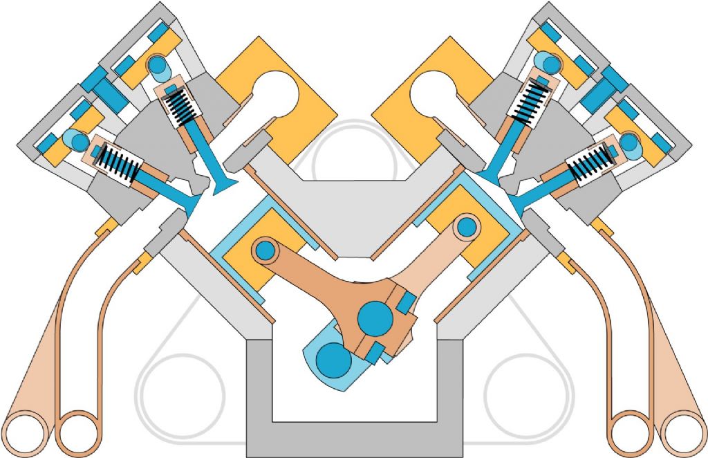
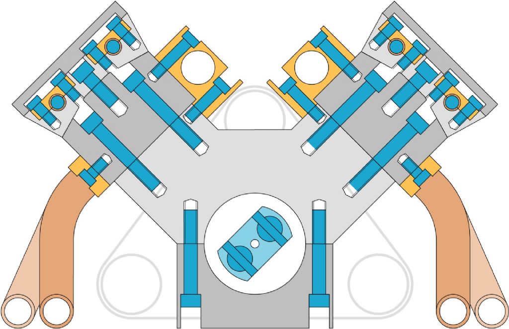
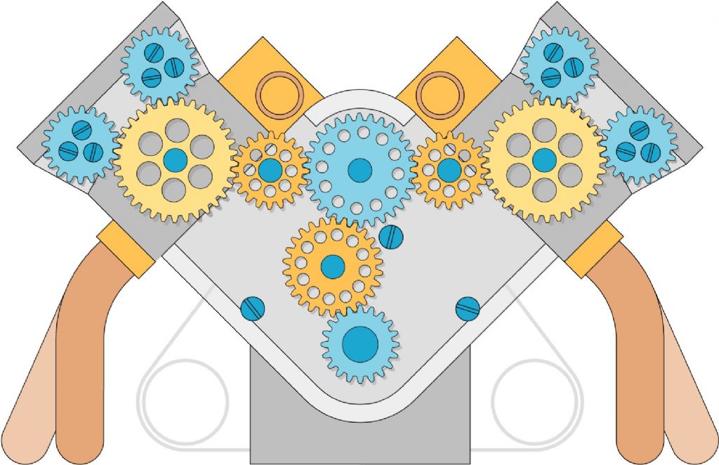
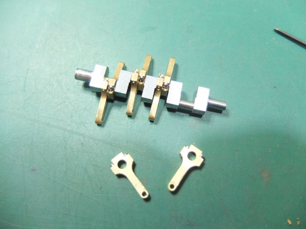
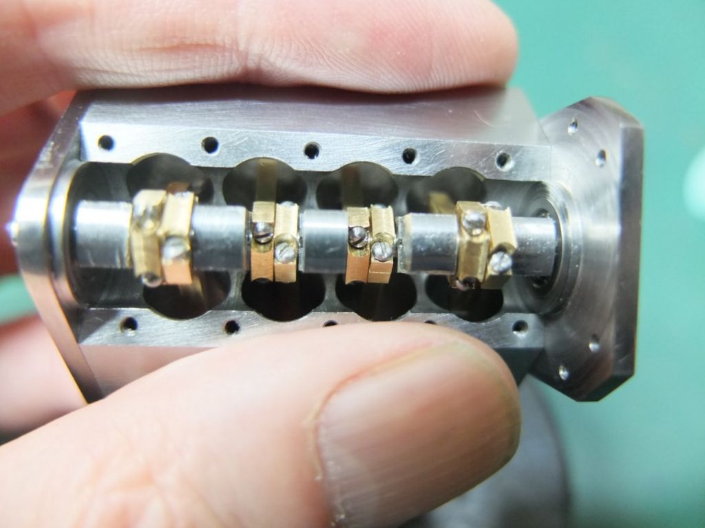
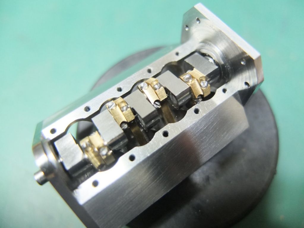
A few months ago, I decided to have a go at making a 1:12 scale Cosworth V8 DFV Formula 1 engine.
It will be a 2-stroke running on air (or CO2?) with a bore of 7.2mm and a stroke of 5mm.
I want to share my progress so far as I’m sure I will need some advice.
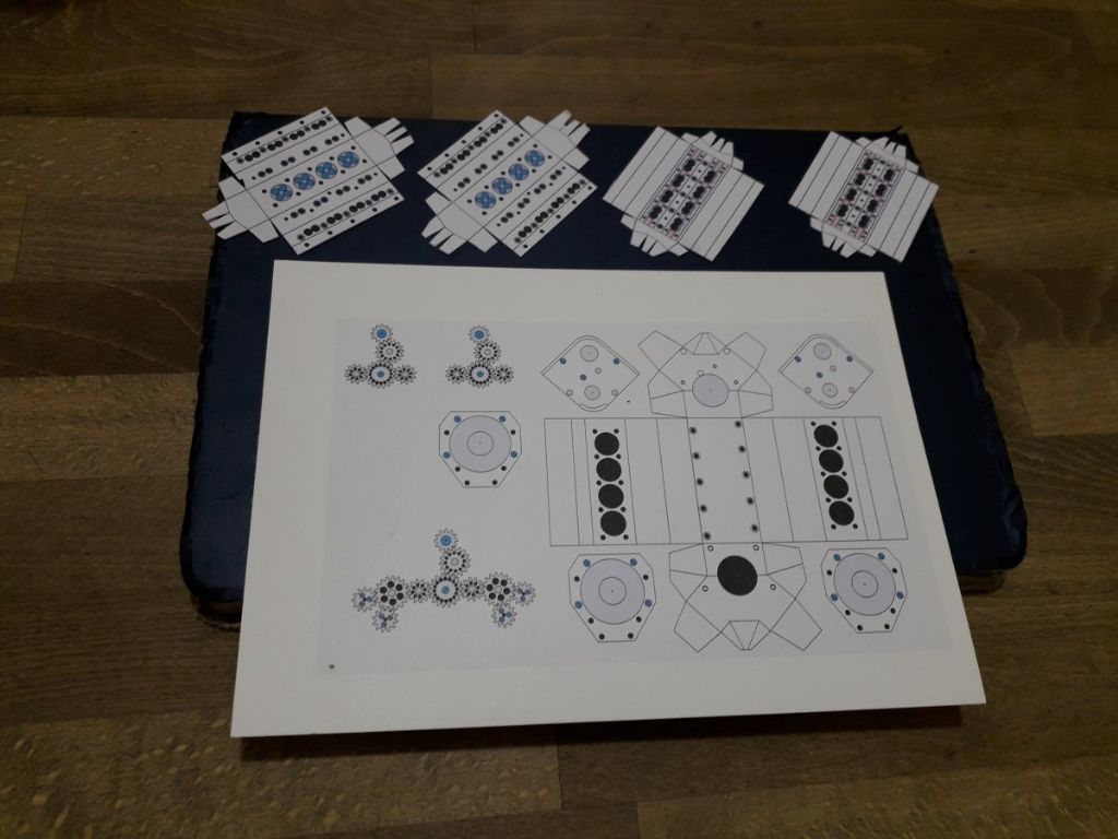
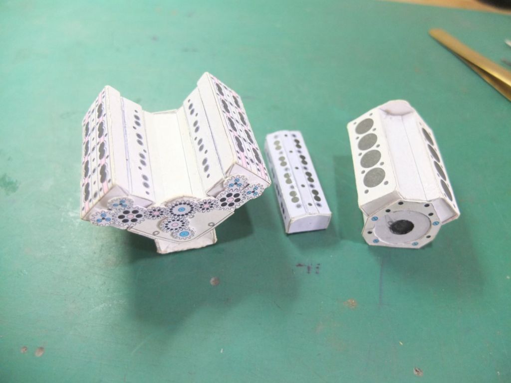
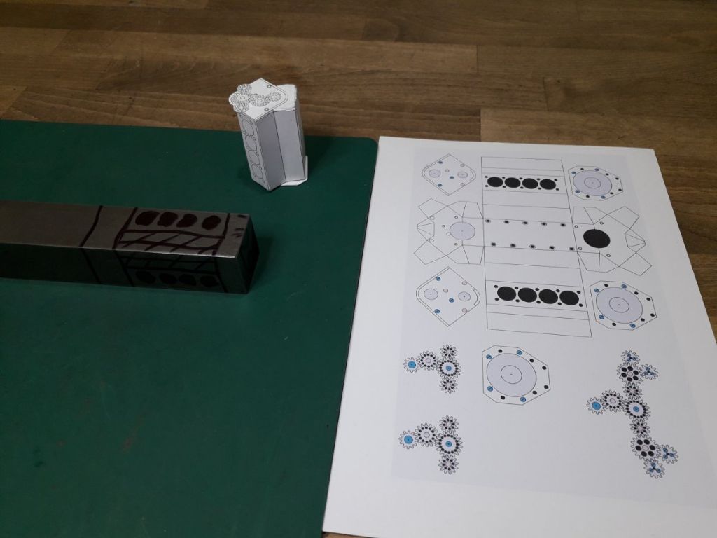
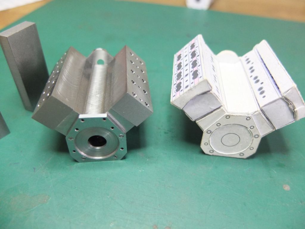
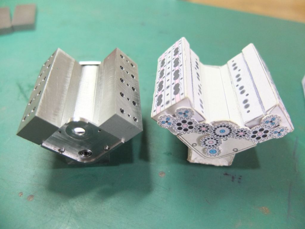
After making the drawings, the first thing I did was make card models of the main components.

This helps me visualise things and see if any screws interfere with each other etc.

The block started life as 1” square mild steel bar.

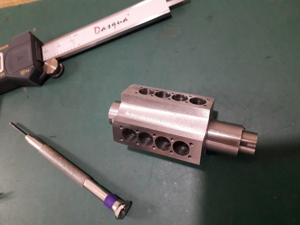
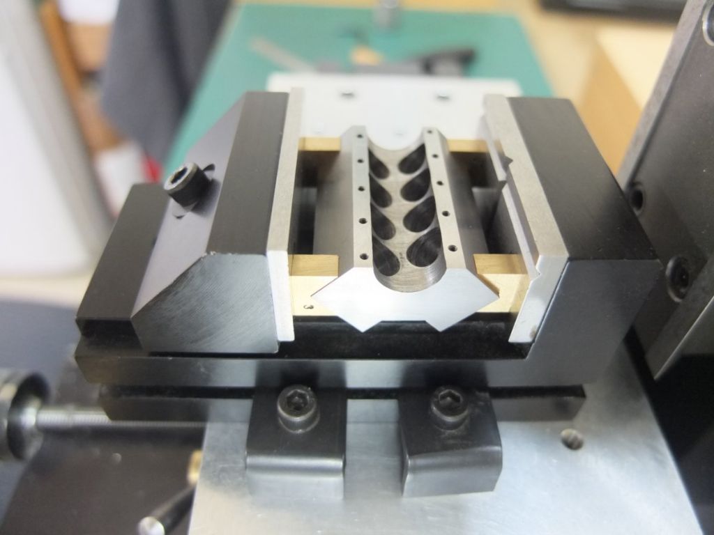
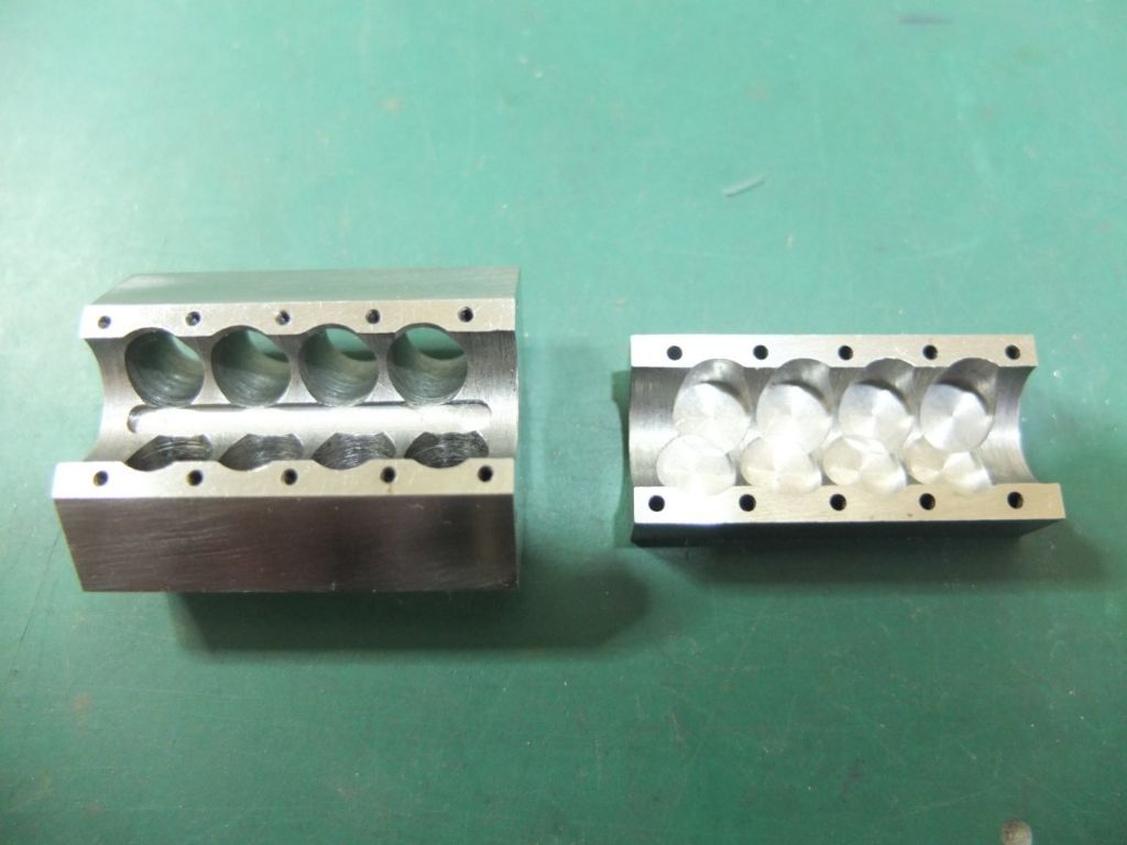
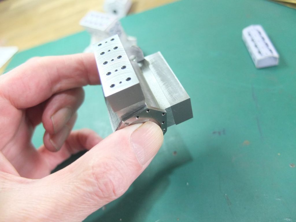
I sawed of a piece about 3” long and this was clocked in the 4 jaw and eccentric bosses, on the crank centre line, were turned at both ends. This gave me an accurate way of holding it while boring out the cylinders and milling the block to shape. In the picture below, the milling is part done.

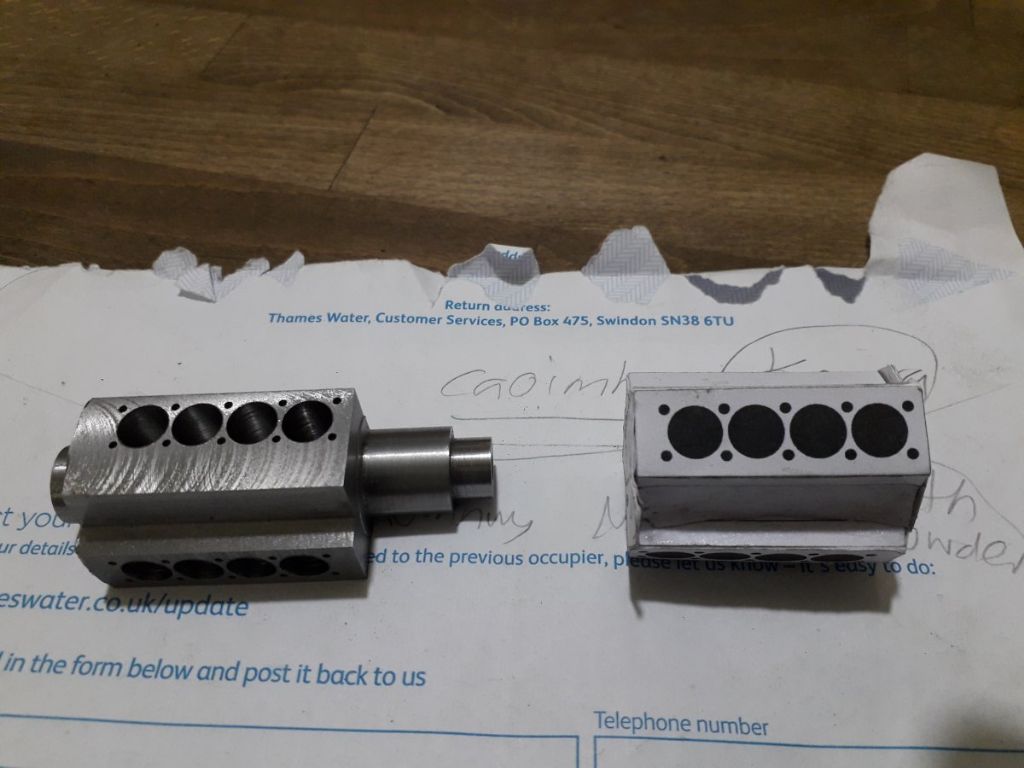
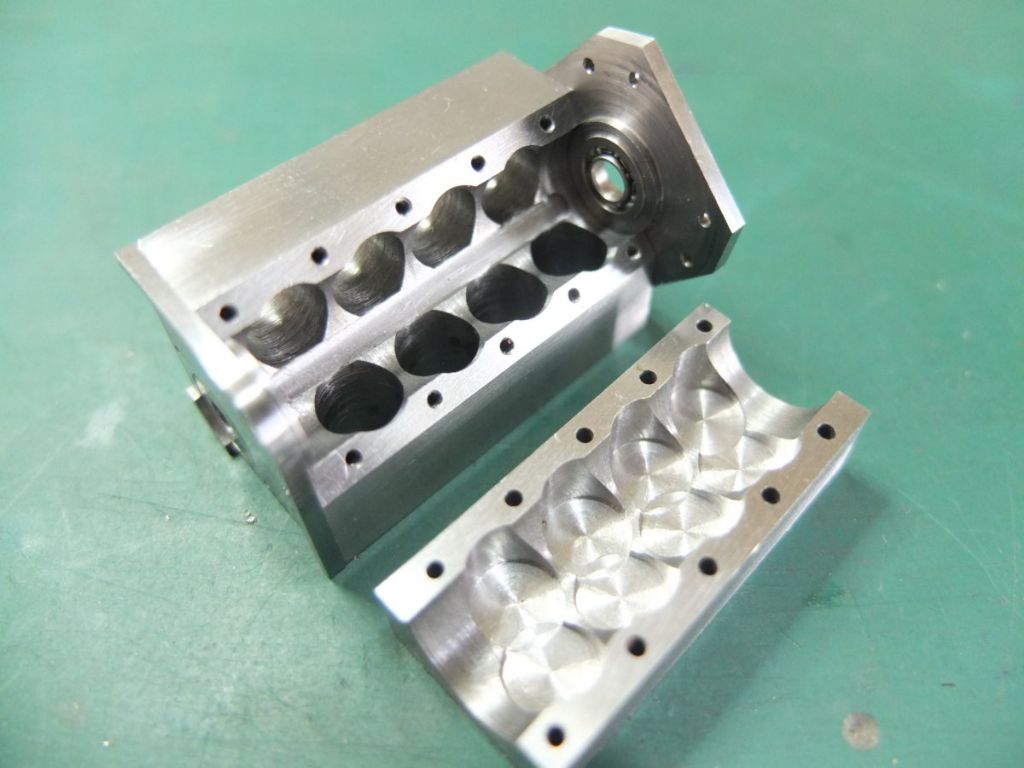
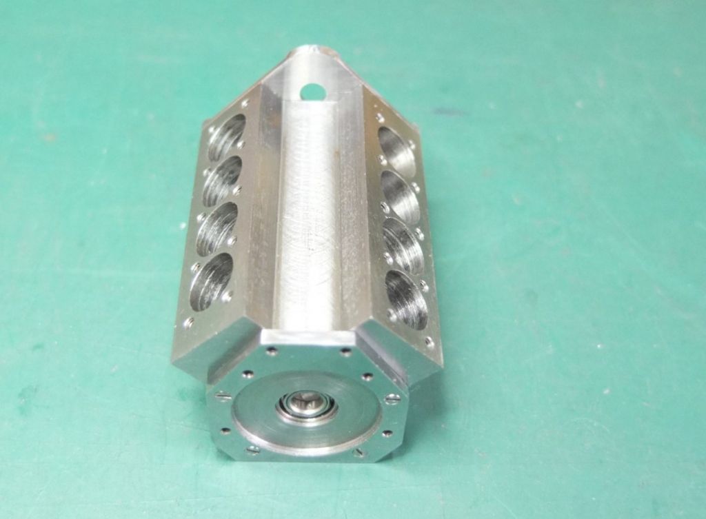
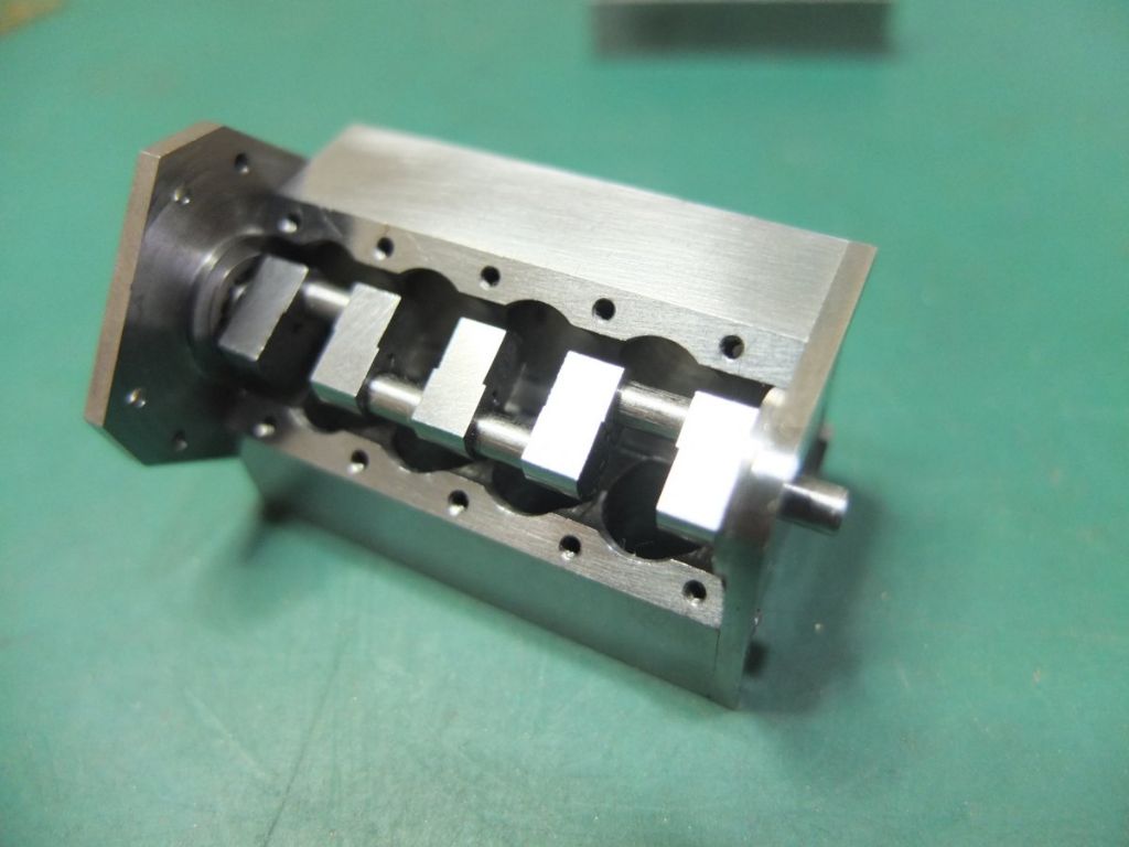
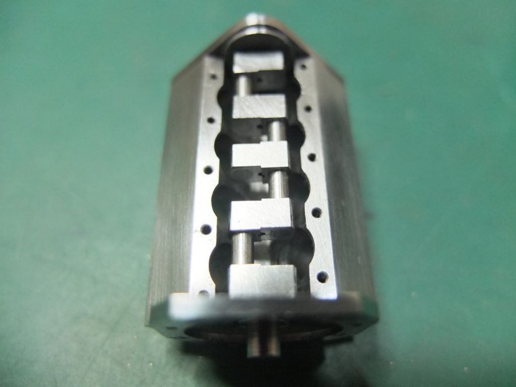
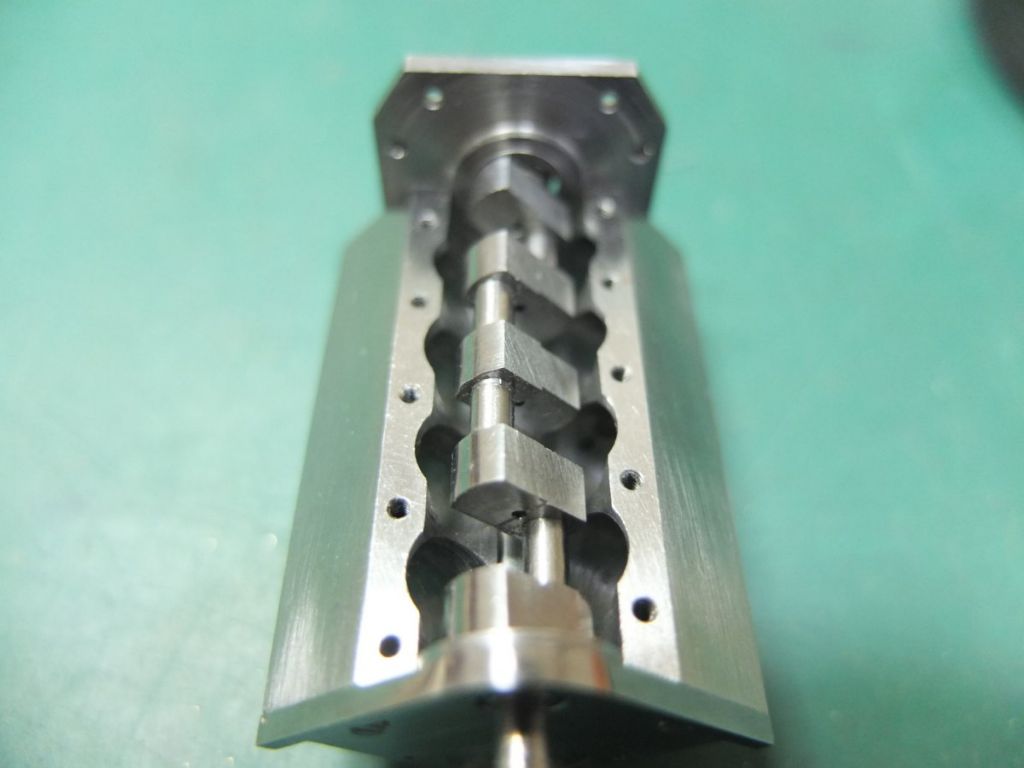
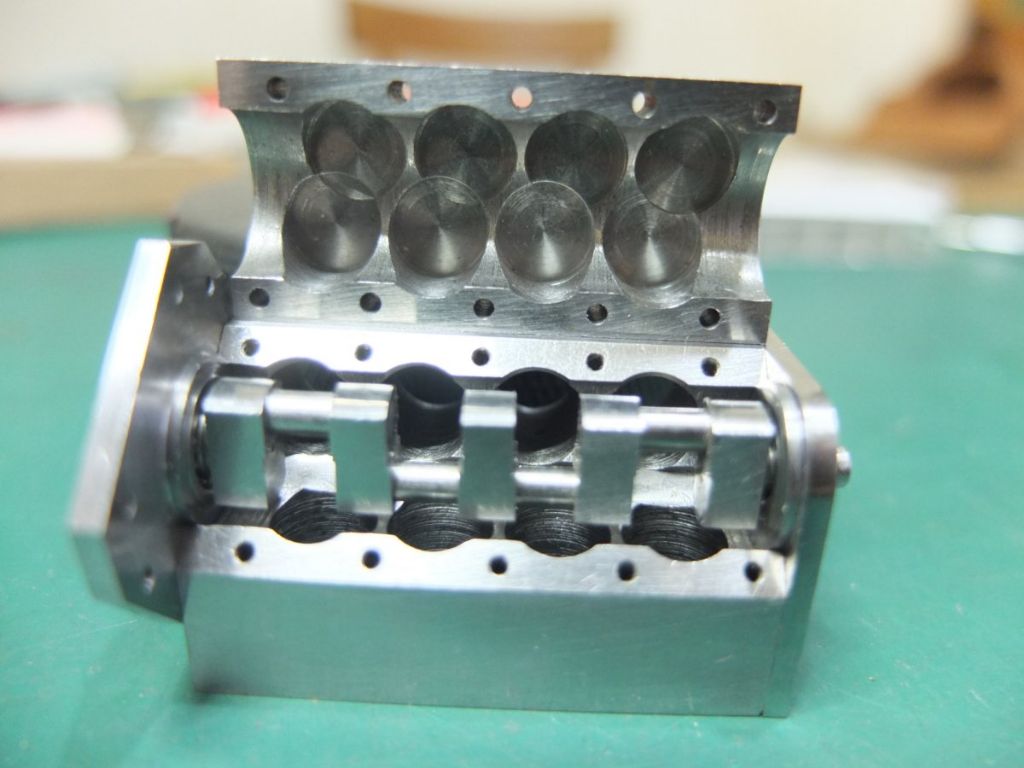
The block, milled to shape. The bores are a bit rough but true. They will have brass liners anyway.

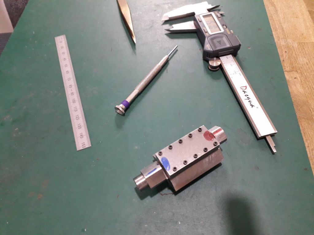
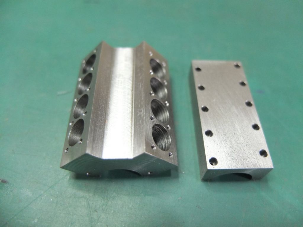
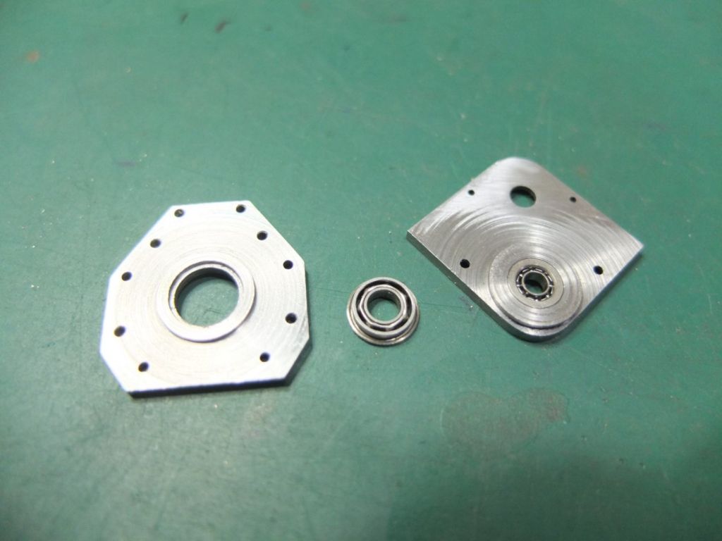
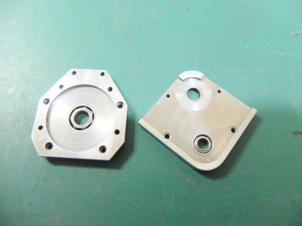
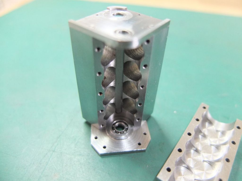
The block was drilled and tapped and the sump blank bolted to it.

The whole assembly was then drilled and bored out as one piece and the bosses removed.

More to follow….
Steve
Edited By Steve Crow on 01/11/2020 14:47:22
Edited By Steve Crow on 01/11/2020 14:48:04
Edited By Steve Crow on 01/11/2020 14:52:27
 Ady1.
Ady1.

