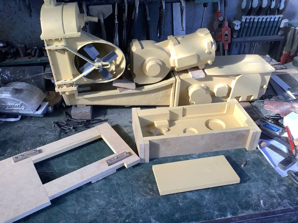
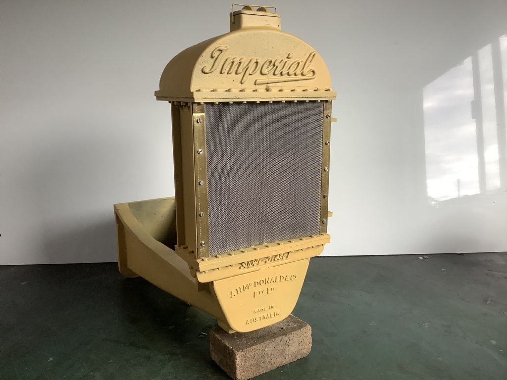
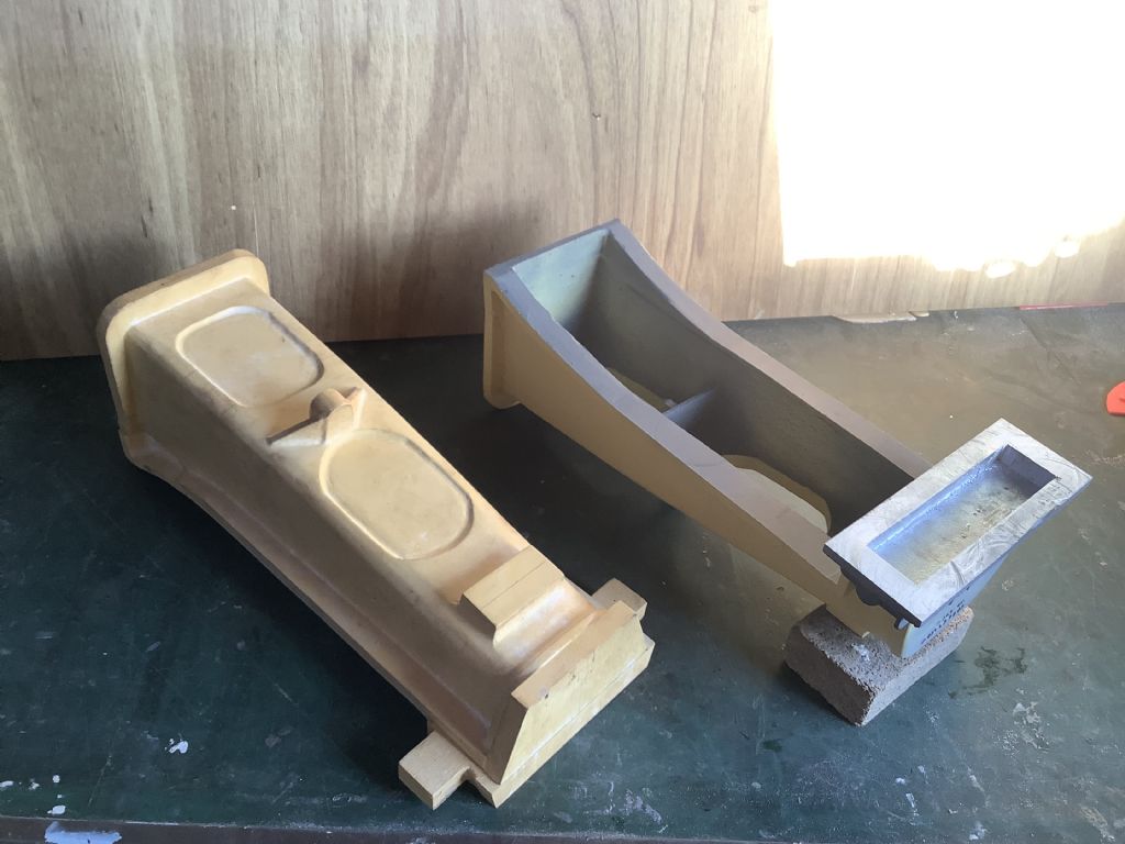
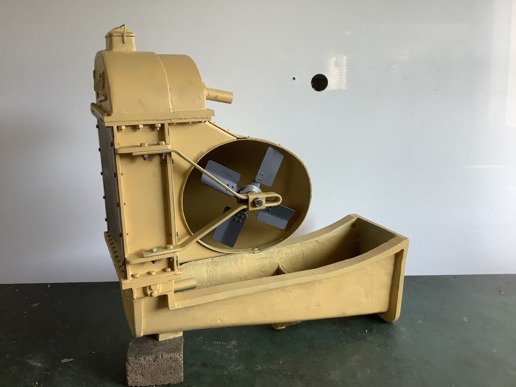
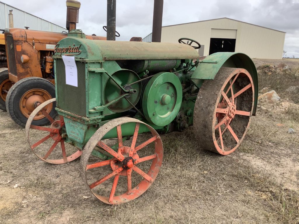
It’s been quit some time since I last contributed to the forum and I am still trying to remember how the system works so excuse any mistakes or double ups. The model I am now making is a 1934 Mc Donald tractor in 1/4 scale. It has a single cylinder two stroke diesel engine driving through a 3 forward / 1 reverse gearbox. The “ignition” is by hot bulb and cooling by thermo siphon The chassis is cast and on the model it’s aluminium as are all the other castings. The photographs show various stages of the construction with the front half ( chassis, radiator and fan) now complete. The engine and gearbox patterns have been made and I hope to cast the gearbox soon. I am lucky in that the full size tractor is only 17 kms from my home and so far I have spent 14 hours taking photographs and taking measurement prior to making CAD drawings and patterns. It is an exciting project to be working on and the learning curve never stops!
Interesting If I am reading under the radiator correctly it's an Australian maker. I thought that the single cylinder hot bulb/semi diesels were a European thing.
Do you have thoughts for the injection system yet?
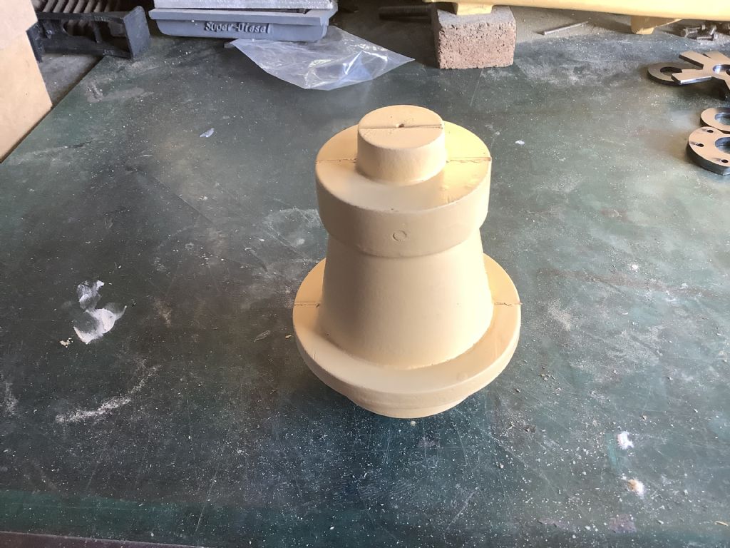
The full size tractor was made in Australia and the design was based on both the Lanz Bulldog for the engine design and the Rumsely tractor for the gearbox arrangement. The model I am making is based on the 1934 model of which there were 50 full size tractors manufactured. At first the engine pointed to the front but was later turned around so that it pointed towards the driver as this gave a better weight distribution of weight over the rear wheels and improved the steering characteristics. The photographs sent in yesterday shows the pattern for the chassis. The patterns and core boxes are made from MDF and are spray painted with “bog” of the type used on car bodies as this gives a finish that can be drawn on with pencil and gives a small fillet in the corners. I have made a model Lister Diesel engine and will use that experience when designing and making the injection system on this tractor and still keep with in the external shape of the full size tractor. I will show you more details when I reach that stage.
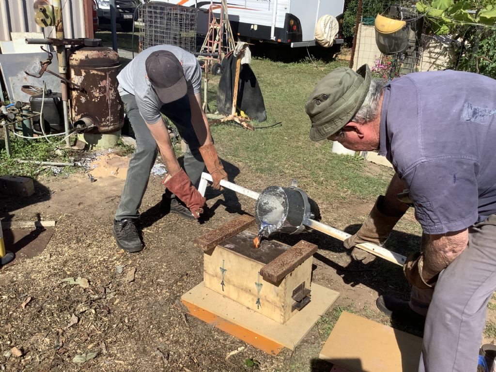
Yes that was my model 6/1 Lister and there is a video of it working on U tube and it was on display at the 2019 MEX. I do have good diagrams of the cam and variable injector system used on the Mc Donald and will try to follow that as much as possible. I have normally made four stroke engines and this is the first two stroke and first with hot bulb and it presents many challenges! The castings shown are some of the largest I have made and push the limits of my equipment and me.
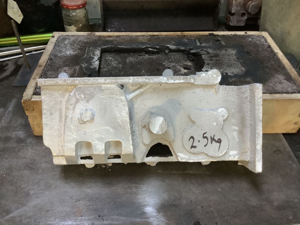
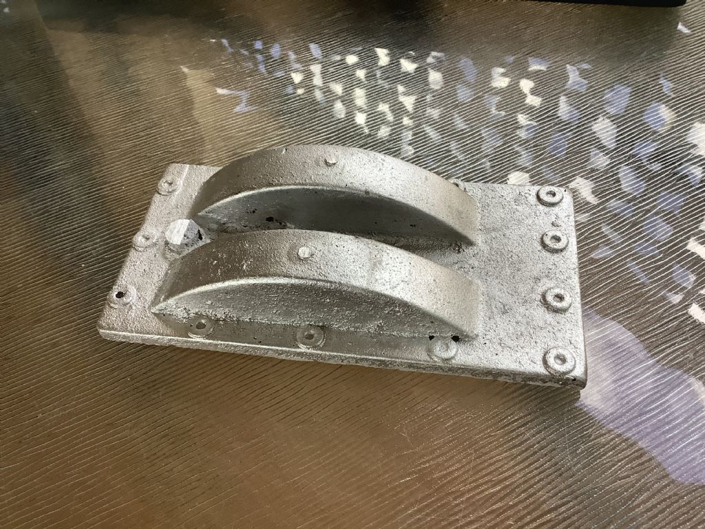
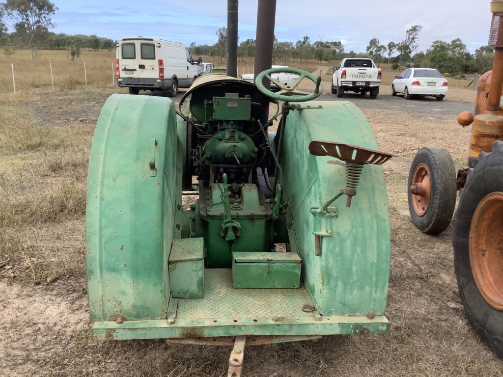
The casting shown above is the result of today’s efforts and was still warm when the photo was taken. It has yet to be cleaned up. The casting is the top cover for the gearbox and the shape can be seen in the photo of the full size tractor. Tomorrow I hope to cast one side of the gearbox as all the patterns and core boxes are now finished. Fingers crossed all goes well!
I didn’t cast the first half of gearbox as I decided to make the patterns and core boxes for both halves. This will enable me to check that all the shafts and retaining bolts will line up. The ‘thinking’ time also allows me to check for mistakes as it is easier to correct them now than find out later! These castings are quite large and I feel that my crucibles are not large enough and may have to call in some help from one of my mates who has facilities capable of handling larger work. I hope to collect the laser cut parts for the wheels as they should be ready by the end of the week.
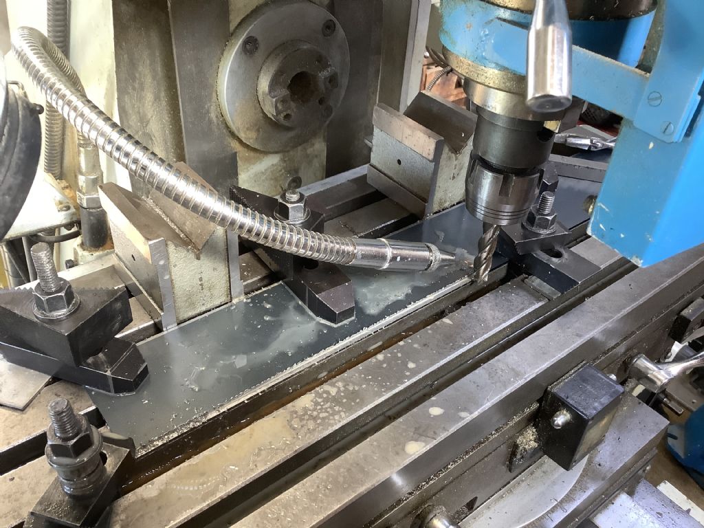
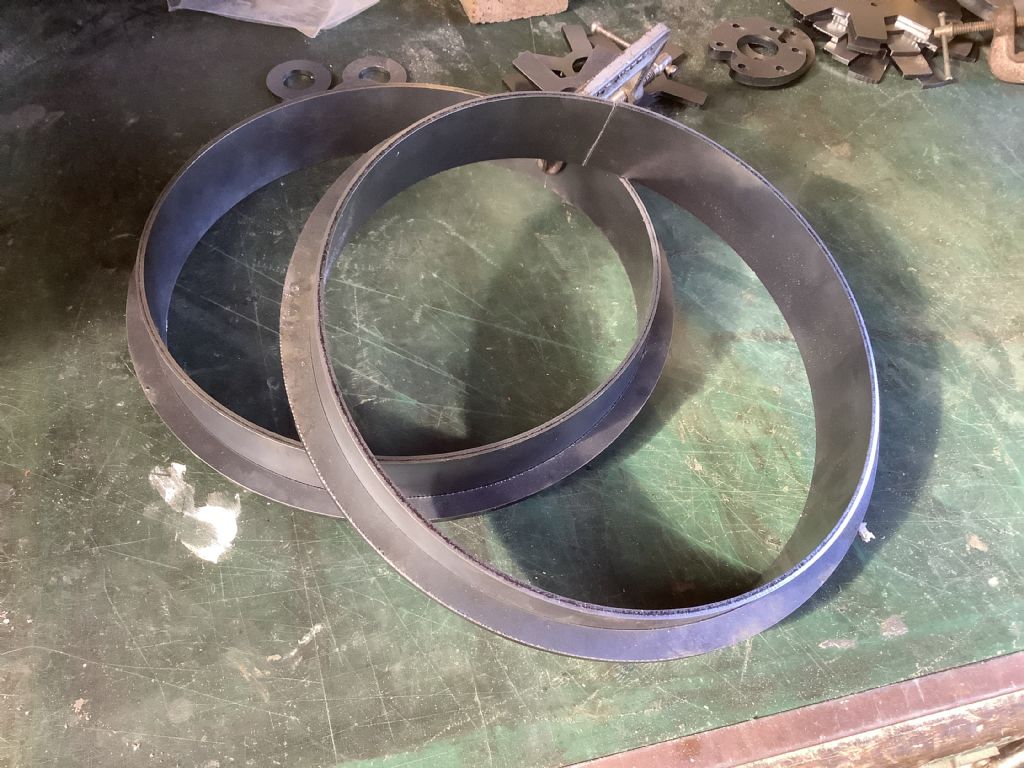
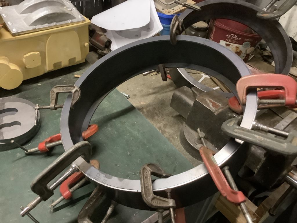
The photo shows work in progress on the front and rear wheels. The strip for both sets of wheels were laser cut from 3mm steel, with the rear wheel strip having a 3×1 step being milled from both long edges. This allows the inner rings to sit in the correct position for silver soldering. The strips for front and rear rims were then rolled to shape. I always make the strips 100mm longer than required as both the start and ends of the strip remain flat and don’t follow the curve. The excess is then trimmed down to fit the rings. On the front wheels the ring is external to provide grip for the steering and on the rear they are internal and provide a position for the spokes. The first half of the gearbox casting is ready to be poured and should be completed by the end of the week.
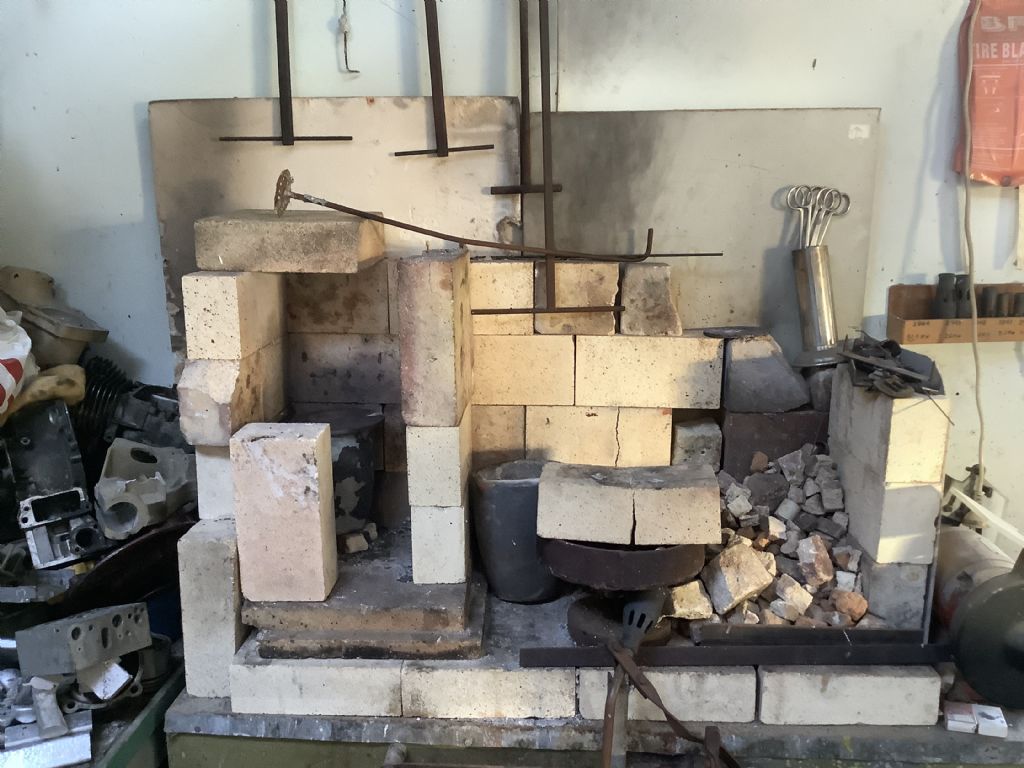
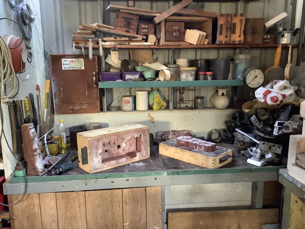
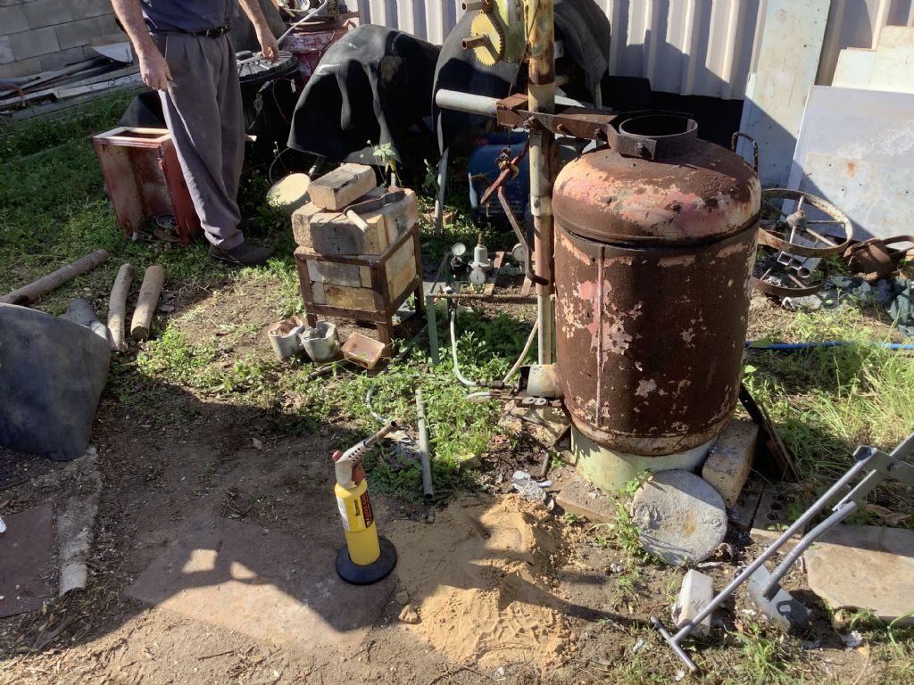
The photographs show my rather untidy foundry area of the workshop. The work bench has a sand storage area underneath, casting boxes above and a small cabinet on the left that holds the tools used in the process. The other photo shows the ‘hot’ area where I melt the aluminium using a gas blow torch. The fire bricks generate a vortex around the crucible. The scrap metal on the right is my stock of usable aluminium – Briggs and Stratton crankcase etc. I do use Coveral11 flux to clean the melt and degassing tablets to dive off any gas in the molten metal. I use both oil bound sand (Petrabond) and a local white sand that I mix with a chemical binder/ hardener. Casting is an enjoyable process but it does take time and if you don’t succeed the first time you just try again !
The half of the gearbox ready for assembly and casting and the pattern for the rear axle supports.
Thanks for that. I bet it gets quite warm in your workshop with it running My teenage son got interested in casting last year so we built a furnace from an old propane cylinder and reclaimed a burner from a space heater as my blowtorch wouldn't generate enough heat. We've done a few things since but haven't really got the hang of making the sand moulds yet hence the curiosity as to what others are using. I've been following your compatriot "Olfoundryman" on youtube for tips to try and improve.
Today was casting day for the first half of the gearbox and it would have been great to report that all went well but it didn’t . The casting process went well but due to a seniors moment and misjudgment a few holes appeared where they were not wanted! I did say “oh bother” but then realised it was just part of the never ending learning curve. I have now modified both the pattern and core box and will also pack the box more firmly next time for a better surface finish.
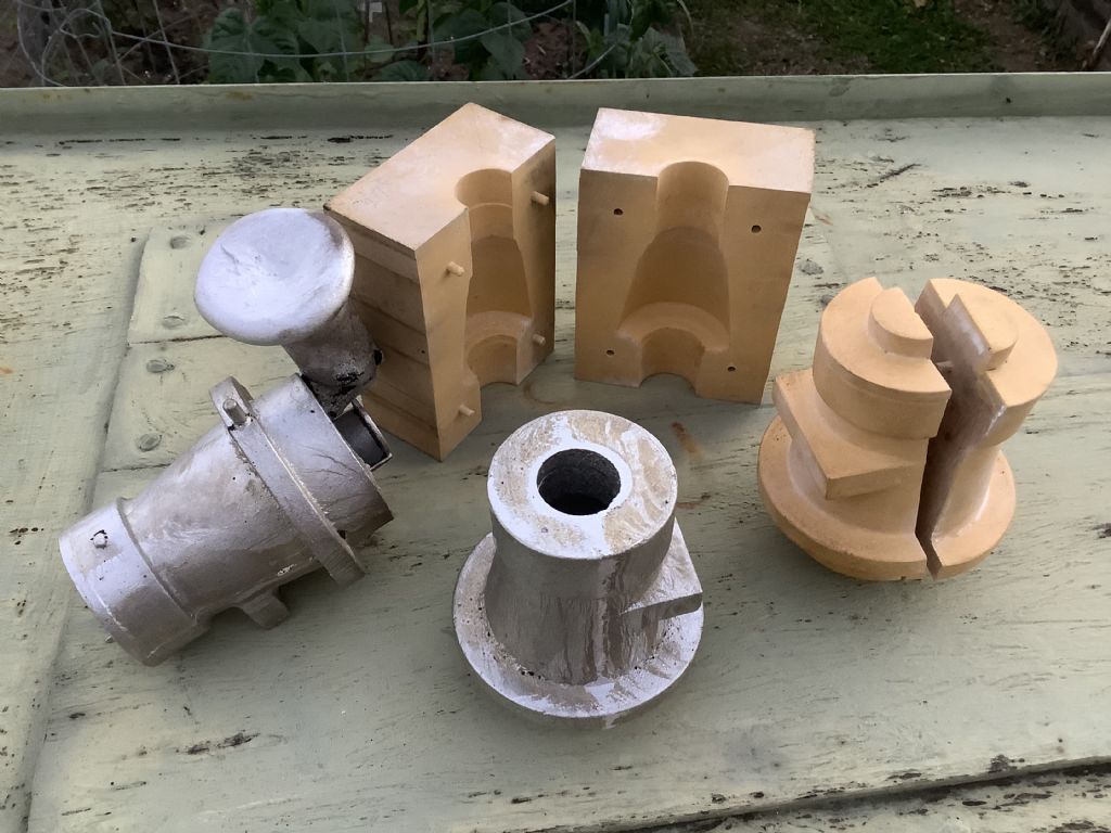
Today I cast ,in aluminium ,the two rear axle supports for the tractor. These bolt onto the side of the gearbox and carry the split axles on two ball races on each side. The photo show the pattern, core box and the casings – one cleaned up and the other complete with runner.i have modified the gearbox pattern to avoid holes and will have a go at casting one of them next week.
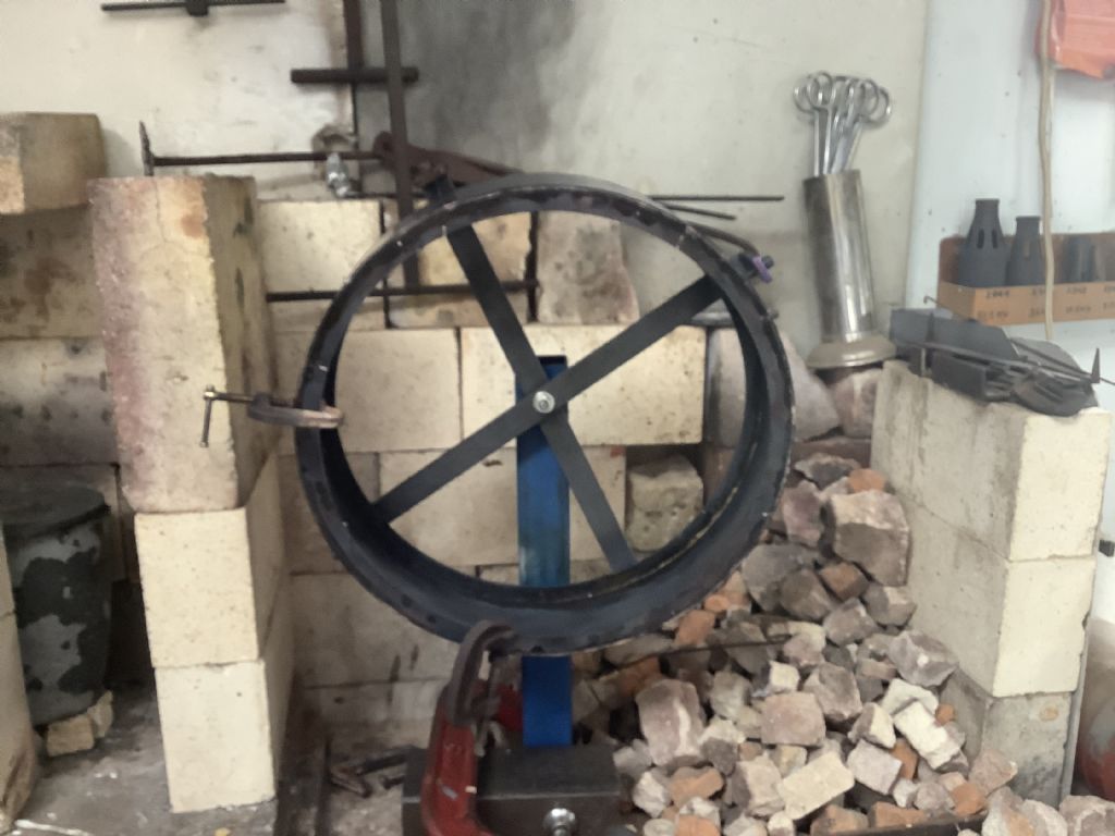
The weather conditions here have stopped casting for a while but there is still plenty to work to do in the workshop. The photograph shows a jig that I made up for silver soldering the rings inside the rear wheels. It was well worth the time and effort as I was able to use gravity to help the solder to flow as the wheel can be rotated when being soldered. By making the jig it gave the set up stability and didn’t fall over also I was able to do both sides in one heat.
A probably daft question on the castings with holes – have you ever tried patching small defects? Perhaps prepare the edges of the missing bits under a flux of some sort and then pour in some new molten metal? From what I can see you have formed all the important bits so just a question of stopping the oil falling out.
After all that effort I did consider blocking up the holes by either welding or liquid steel from a tube but decided there was only one way and that was to repeat the process with a modified pattern and core box. The fault was mine ( in the design) and not the actual casting process and all should be OK next time. As we cast outside and the weather was not good it was back in the workshop and I have now made up the rear wheel rims to the point of etch primer.