From the ground up!

Advert

From the ground up!

Home Forums Work In Progress and completed items From the ground up!

Viewing 25 posts - 1 through 25 (of 97 total)
  • Author
    Posts
  • #31255
    JohnM
    Participant
      @johnm51917

      Myford ML4 – Attempted Restoration

      Advert
      #403351
      JohnM
      Participant
        @johnm51917

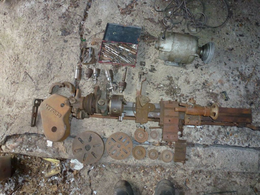
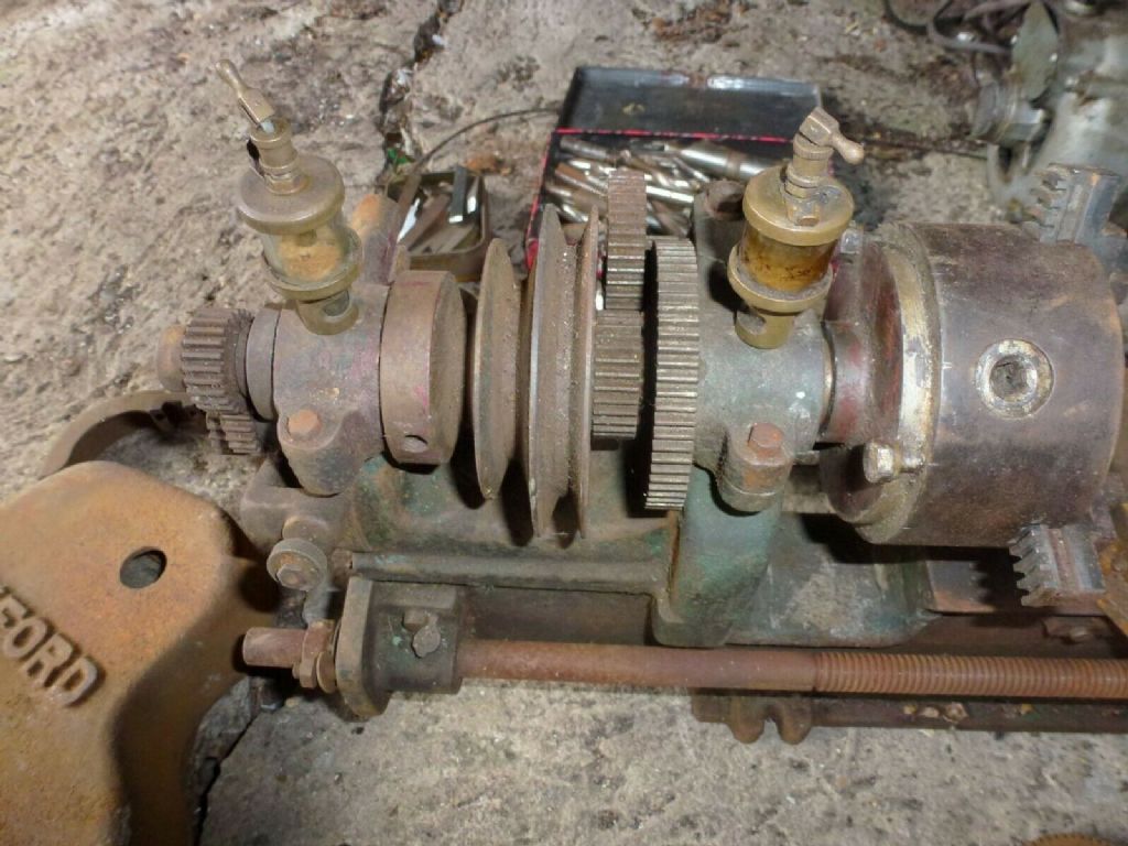
        Sure that the seller dug this one up from his back garden. It looks in such a sorry state but I'm determined to give this a whole new lease of life.I will be working day and night to bring it back to as near to original as I can. Please check back often as I will be posting my progress as I go. Already getting some great help on these forums.

        s-l1600 (2).jpg


        s-l1600 (5).jpg


        s-l1600 (6).jpg

        Edited By John Milton 2 on 03/04/2019 14:58:34

        Edited By John Milton 2 on 03/04/2019 15:00:08

        #403360
        Nigel Graham 2
        Participant
          @nigelgraham2

          I'm sure we all look forwards to seeing the poor old thing back as it should be!

          It's noticeably far worse from saddle to tail end – under a leaking roof?

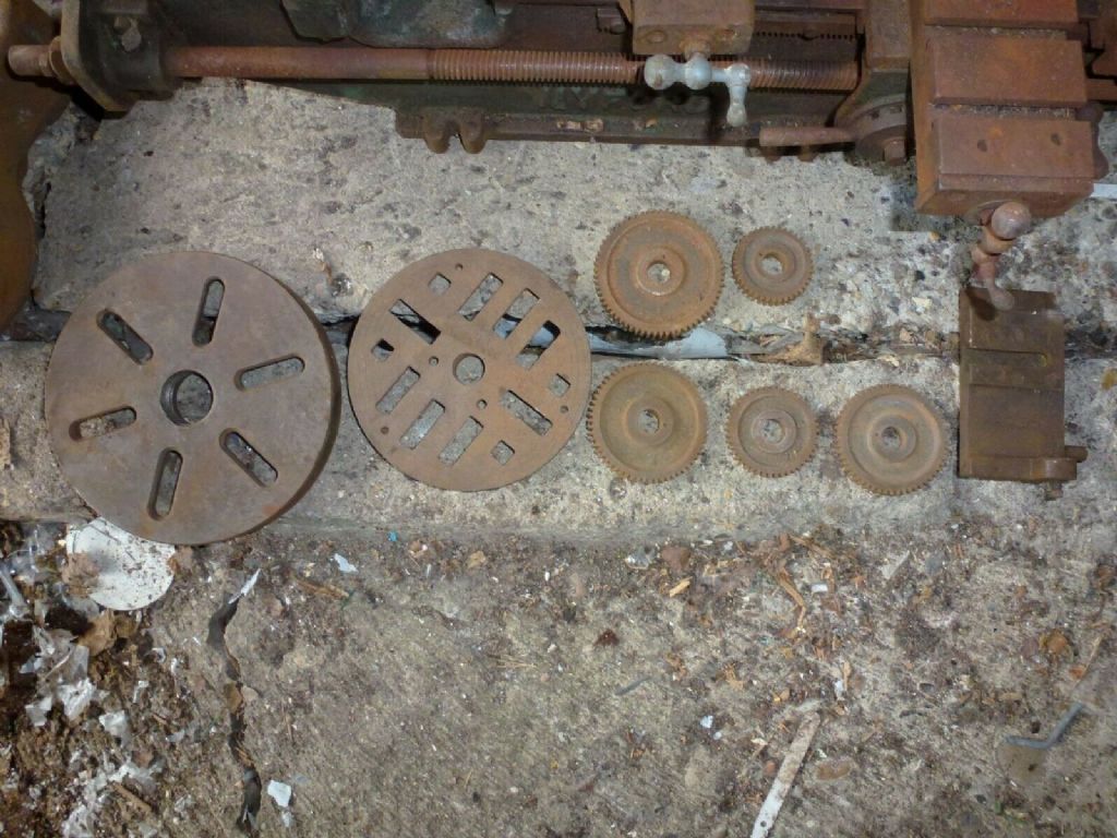
          The right-hand faceplate looks Drummond-pattern though the Myford name's clear on the guard.

          The four small holes in that – and those two in the cross-slide – look as if user-drilled to hold specific work-pieces or accessories, but overall it does look as if that user was a careful one – no obvious "oops" grooves in the faceplates, or missing teeth visible in the headstock wheels.

          #403452
          JohnM
          Participant
            @johnm51917

            There are a couple of damaged teeth in the 65 .. I mean 63 tooth gear noticed by Brian Wood who has been steering me along in the right direction since I signed up here. I'm making some good progress but I think to be honest this is just a stepping stone towards a different maybe more modern or usable future Lathe. I think with Brian's help it is now decided it is an ML2 as the headstock is all dismantled and if I'm right that can only be an ML2 or an ML4 threads are 2.02mm Should have it figured out when its finally done.

            #403457
            Hopper
            Participant
              @hopper

              Looks like it was possibly a woodwoorker's lathe with the motor belted straight to the lathe spindle pulley with no countershaft, making rpm too high for most metalworking. Holes in the cross slide possibly then for a woodworker's tool rest.

              Looks like you have a job there for sure. But if the half of the bed towards the headstock is not too bad you should be able to make something useable out of it. Surprising what these old lathes can be nursed into doing. Beware though: vintage machine tool restoration can turn into a hobby of its own!

              Edited By Hopper on 04/04/2019 00:33:50

              #403486
              Brian Wood
              Participant
                @brianwood45127

                Hopper,

                The cross slide holes you spotted at the control end were stud positions to clamp the top slide in one of two positions, swivelling about the mid-position hole as the fulcrum point.

                Regards

                Brian

                #403488
                Hopper
                Participant
                  @hopper

                  Aha. Makes perfect sense now you point it out.

                  #403496
                  Brian Wood
                  Participant
                    @brianwood45127
                    Posted by John Milton 2 on 03/04/2019 23:51:36:

                    There are a couple of damaged teeth in the 65 .. I mean 63 tooth gear ——

                    You were right the first time John, the bull wheel has 65 teeth

                    The ML2 spindles had 3/4 inch x 9 tpi Whitworth nose thread, your's matches those dims

                    Brian

                    Edited By Brian Wood on 04/04/2019 09:38:27

                    #403503
                    JohnM
                    Participant
                      @johnm51917
                      Posted by Brian Wood on 04/04/2019 09:35:38:

                      Posted by John Milton 2 on 03/04/2019 23:51:36:

                      There are a couple of damaged teeth in the 65 .. I mean 63 tooth gear ——

                      You were right the first time John, the bull wheel has 65 teeth

                      The ML2 spindles had 3/4 inch x 9 tpi Whitworth nose thread, your's matches those dims

                      Brian


                      Just a stab at my level of humour Brian. two missing or damaged teeth didn't count


                      Are we agreed this is an ML2? I believe the ML1 was cast as a single piece and this one is certainly in two parts. One large part being used as a door stop and the other part or parts on my bench. Amazing to see how well it cleans up after standing outside for so long. Good old British engineering.

                      Edited By John Milton 2 on 04/04/2019 10:38:43

                      #403506
                      JohnM
                      Participant
                        @johnm51917

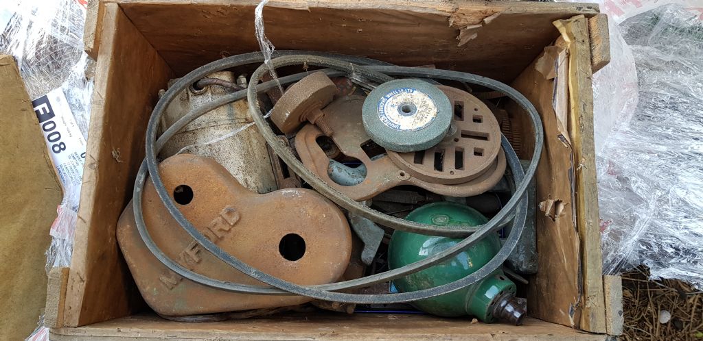
                        20190328_095307lll.jpg

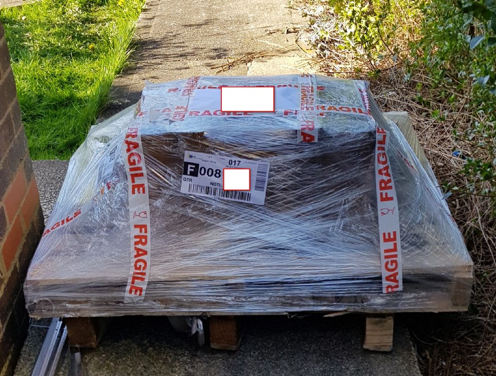
                        So starting here, I came home to find this parked in my front pathway and set about unpacking like a little boy with a new toy.

                        20190328_095454.jpg

                        I always find there are a few little bonuses when you buy second hand and already noticed an old Lathe lamp in the box.Possible up-cycle for some posh architect auction sale in the future.

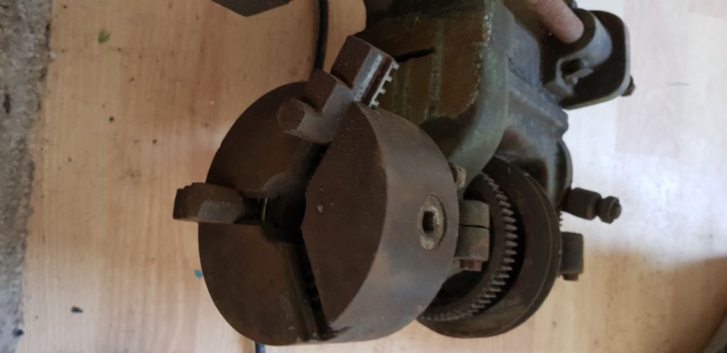
                        20190328_100528.jpg

                        horror of horrors one of the Chuck teeth is missing! After a call to the seller it was found on the floor of the delivery van and posted to me by the courier. I was worried it would be swept out but it all turned out well in the end on that part.

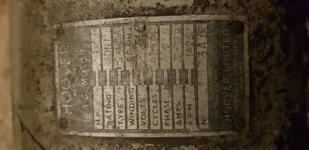
                        20190328_230949.jpg Hoover motor ,checked out okay and very quiet despite looking very tired. will probably run forever though.

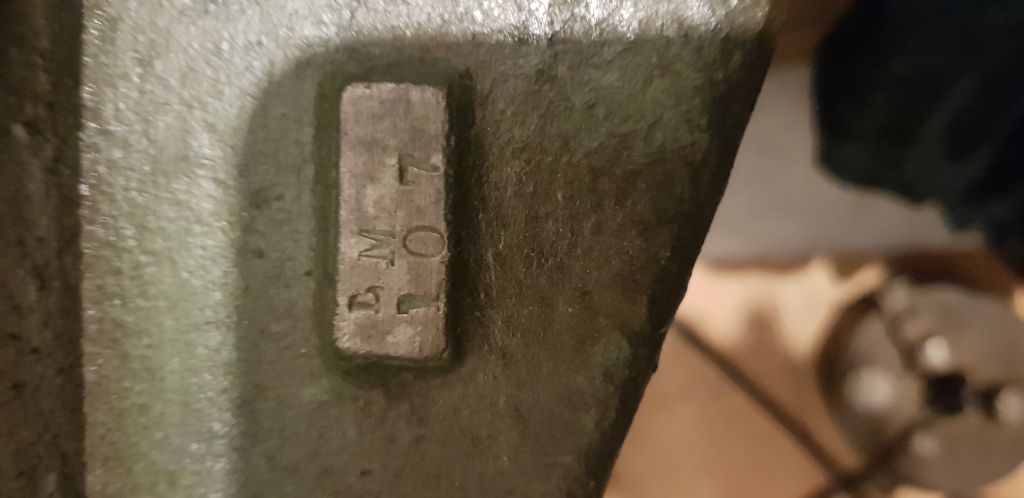
                        20190328_221632 (1).jpg

                        There are no serial numbers I can find online for any of the early Myford Lathes. I noticed that there are some newly found documents that are being sifted through and will be posted when scanned and sorted.

                        #403511
                        JohnM
                        Participant
                          @johnm51917

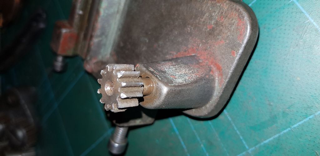
                          More broken or damaged teeth found. This is sitting on the screw thread and is attached to the saddle. Hopefully using the correct terminology here. Should I be worried?

                          20190403_235903.jpg

                          #403520
                          JohnM
                          Participant
                            @johnm51917

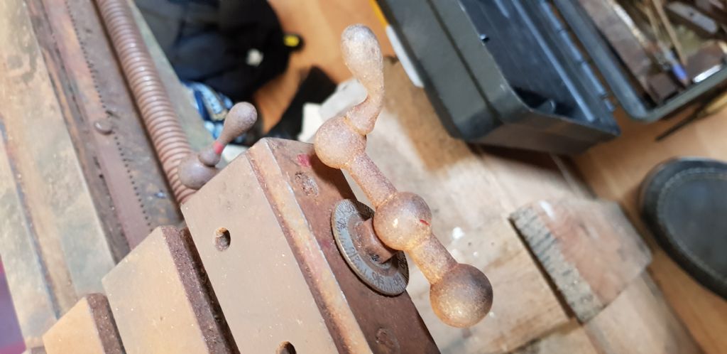
                            Should I Heat? Beat? or Replace? If only I had a Lathe to make one or two! hahaha

                            20190328_113411.jpg

                            #403526
                            Georgineer
                            Participant
                              @georgineer

                              Some simple measurements and observations can identify which of the different models ML1 to ML4 one is faced with:

                              ML1 & 2: 3 1/8" centre height, 15" between centres, 3 1/2" cross slide travel.

                              ML3 & 4: 3 1/2" centre height, 24" between centres, 4 1/2" cross slide travel.

                              ML1 & 3 ('Standard' models): Spindle bearings direct in headstock.

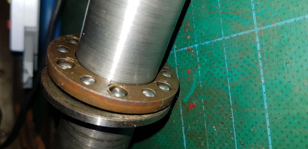
                              ML2 & 4 ('Superior' models): Bronze spindle bearings, shrouded ball thrust race.

                              My understanding from lathes.co.uk is that the cast-in headstock was abandoned in 1937, so from then until the ML1 and ML3 went out of production in 1941, all models had the removable headstock.

                              George

                              #403530
                              JohnM
                              Participant
                                @johnm51917
                                Posted by Georgineer on 04/04/2019 11:27:17:

                                Some simple measurements and observations can identify which of the different models ML1 to ML4 one is faced with:

                                ML1 & 2: 3 1/8" centre height, 15" between centres, 3 1/2" cross slide travel.

                                ML3 & 4: 3 1/2" centre height, 24" between centres, 4 1/2" cross slide travel.

                                ML1 & 3 ('Standard' models): Spindle bearings direct in headstock.

                                ML2 & 4 ('Superior' models): Bronze spindle bearings, shrouded ball thrust race.

                                My understanding from lathes.co.uk is that the cast-in headstock was abandoned in 1937, so from then until the ML1 and ML3 went out of production in 1941, all models had the removable headstock.

                                George

                                Thanks for the info George. I guess I will find out when it's all back together. Brian Wood has tried to help me to identify it but I am far better at rust removal than working out. No great rush as I am poodling along right now with the clean up.

                                #403531
                                Hopper
                                Participant
                                  @hopper

                                  I would heat that handle up red and bend back straight. I've made a few similar for the old M-type using a ball turning tool. Stick the toolbit forward past the pivot point to turn the convex curve. You'll be able to do that once you get her up and running.

                                  #403538
                                  Georgineer
                                  Participant
                                    @georgineer
                                    Posted by Brian Wood on 04/04/2019 09:35:38:

                                    The ML2 spindles had 3/4 inch x 9 tpi Whitworth nose thread, yours matches those dims

                                    Brian

                                    The presence of a serial number, the latest type of changewheel guard, the proportions of the bed and the tumbler reverse makes me think that you have a late model ML4.

                                    If so, I would expect the spindle nose thread to be 1 1/8" x 12 tpi, Whitworth form. The only difference between this spindle nose and the later ML7 is that the register (the plain bit at the left-hand end of the thread) is the same diameter as the thread, whereas the ML7 has a 1 1/4" diameter register. ML7 accessories will fit, but with limited accuracy. For full accuracy you would need to fit an accurately turned collar to enlarge the register to 1 1/4"

                                    Earlier ML1-2-3-4s had 7/8" diameter threads with either 9 or 12 tpi and a 7/8" register. I have never discovered whether this was model specific or at the choice of the purchaser. That said, my ML4 has a 7/8" BSF thread (11 tpi) on a non-myford spindle, so there are oddities to be found.

                                    George

                                    #403540
                                    Brian Wood
                                    Participant
                                      @brianwood45127

                                      George,

                                      Looking through the pictures John has sent me on Dropbox, the spindle nose looks like 3/4 inch but measured against a ruler, so it is probably 7/8 inch. The nose thread is certainly not 12 tpi, it is much coarser and again I have had to judge that from a ruler held against it

                                      There is an odd rearward facing lug on John's lathe forming part of the rear spindle bearing, a feature new to me and certainly not present on my late father's ML4 that he bought new in 1945. I thought that was a feature of the earlier lathes, but I have no reason to believe that.

                                      I modified my Dad's lathe with the larger diameter spindle collar of 1.250 inches to make ML7 chucks etc fit instead, the change to upgrade one of 7/8 inch thread is major, needing a new nose altogether but it can be done

                                      Regards

                                      Brian

                                      Brian

                                      #403541
                                      JohnM
                                      Participant
                                        @johnm51917
                                        Posted by Hopper on 04/04/2019 11:36:08:

                                        I would heat that handle up red and bend back straight. I've made a few similar for the old M-type using a ball turning tool. Stick the toolbit forward past the pivot point to turn the convex curve. You'll be able to do that once you get her up and running.

                                        Cheers Hopper, I have only used a wood Lathe years ago at night school but have meddled with the small simple lathe that is in my albums. Little steps for me to start with and if I break the handle straightening it then that's first on the list of things to try. I could probably make one on the little Lathe if I can get this done before I sell it on.

                                        #403542
                                        JohnM
                                        Participant
                                          @johnm51917

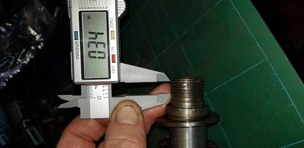
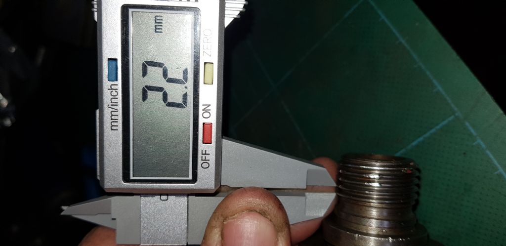
                                          I have a cheap digital caliper if that would help in the measuring and identification? All in bits now so no problem. I appreciate all the help and just glad to have a unique Lathe possibly an ML4 1/2

                                          #403544
                                          JohnM
                                          Participant
                                            @johnm51917

                                            Any help?

                                            20190404_123554.jpg20190404_123715.jpg

                                            #403545
                                            JohnM
                                            Participant
                                              @johnm51917

                                              20190404_123747.jpg

                                              #403546
                                              JohnF
                                              Participant
                                                @johnf59703

                                                "More broken or damaged teeth found. This is sitting on the screw thread and is attached to the saddle. Hopefully using the correct terminology here. Should I be worried?"

                                                John M, not 100% sure but that looks like the drive gear that connects to the rack ? not the lead screw ? Difficult to be completely sure but it looks to me as though it should clean up and work OK.

                                                Looking at the bed, again it really needs to be hands on inspection but it appears to be badly corroded at the back ? After rust removal you may need to consider re-grinding, if this is the case look at local engine boring grinding services – they usually have a machine capable of grinding engine blocks and cylinder heads. They are limited to grinding the top surface only but it gives you a head start, a pal in my village had a Super 7 done – work out very well after some handwork to finish.

                                                Good luck with the re-build John

                                                #403554
                                                Nicholas Farr
                                                Participant
                                                  @nicholasfarr14254
                                                  Posted by John Milton 2 on 04/04/2019 12:37:19:

                                                  Any help?

                                                  20190404_123554.jpg20190404_123715.jpg

                                                  Hi, by my reckoning, it is 12 T.P.I.

                                                  Regards Nick.

                                                  #403556
                                                  Howard Lewis
                                                  Participant
                                                    @howardlewis46836

                                                    I have been helping a friend to get, what we believe to be, a ML2, operational. At least it was in better condition than John Milton 2's barn find!

                                                    It has a bolt on Headstock, 3 1/2" Centre Height, 15" Centres, but the Mandrel thread is 7/8 x 9 tpi (which is the standard 7/8 BSW) instead of the later 7/8 x 12 tpi. So maybe it is a hybrid with an early Mandrel grafted onto a later machine?

                                                    I have just made an adaptor, which will allow the ML7 standard 1 1/8 x 12 tpi ) chucks to fitted to the 7/8 x 9 tpi Mandrel.

                                                    Any thoughts, anyone?

                                                    But, more power to your elbow, John. You will have a great deal of satisfaction when it is refurbished and up and running, as a useable machine.

                                                    Howard

                                                    #403557
                                                    Georgineer
                                                    Participant
                                                      @georgineer

                                                      John,

                                                      Yes , a very helpful view. Taking 0.34" for four threads, I agree with Nick that it's 12 tpi. Scaling the view from that, I get very close to 1 1/8" for the register diameter. The thread diameter should be a little less than that to give a slightly slack fit. This allows the register to align screw-on accessories accurately. The register should be a very accurate 1.125" with no lumps or bumps or burrs.

                                                      The lathe was conceived and built in inches-and-fractions, so taking measurements in millimetres (usually a practice to be encouraged) doesn't provide very much help.

                                                      George

                                                    Viewing 25 posts - 1 through 25 (of 97 total)
                                                    • Please log in to reply to this topic. Registering is free and easy using the links on the menu at the top of this page.

                                                    Advert

                                                    Latest Replies

                                                    Viewing 25 topics - 1 through 25 (of 25 total)
                                                    Viewing 25 topics - 1 through 25 (of 25 total)

                                                    View full reply list.

                                                    Advert

                                                    Newsletter Sign-up