The Workshop Progress Thread 2019

Advert

The Workshop Progress Thread 2019

Home Forums Work In Progress and completed items The Workshop Progress Thread 2019

Viewing 25 posts - 1 through 25 (of 261 total)
  • Author
    Posts
  • #388612
    JasonB
    Moderator
      @jasonb

      Report your modelling and workshop milestones in this thread. Anything else should go into the What did you do thread

      2018 posts can be found in this thread


      Edited By JasonB on 01/01/2019 07:34:58

      Advert
      #31241
      JasonB
      Moderator
        @jasonb
        #388619
        Ron Laden
        Participant
          @ronladen17547

          Jason, your engine is coming along nicely, looking really good. Ball bearings and not plain bearings.? just wondered what your thinking was on that.

          Ron

          #388629
          JasonB
          Moderator
            @jasonb

            Ron, the flame lickers don't have a lot of power so the ball races should offer less friction than bronze. have also gone for unshielded for the same reason.

            #388631
            Ron Laden
            Participant
              @ronladen17547
              Posted by JasonB on 01/01/2019 10:08:30:

              Ron, the flame lickers don't have a lot of power so the ball races should offer less friction than bronze. have also gone for unshielded for the same reason.

              I thought it must have something to do with ease of running, is the Forest engine similar re power or does the gas mix give them more.

              #388658
              JasonB
              Moderator
                @jasonb

                The Forest would have more power though the original was only rated at 1/15th horsepower from it's 2.5" bore

                #388798
                Joseph Noci 1
                Participant
                  @josephnoci1

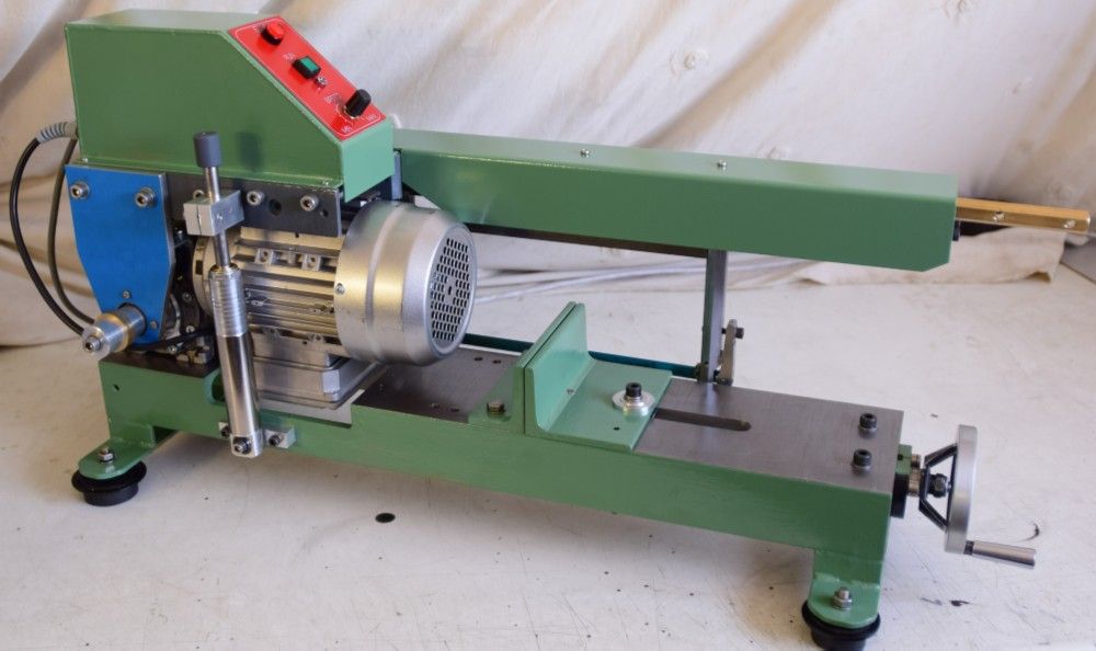
                  In late 2017 I obtained a neat 3 phase 250watt motor with attached Varvel 100:1 gearbox and thought that was ideal for a bench powered hacksaw. It sat under that bench for a year..Mid December last year I challenged myself by starting the project, but on the basis that I do it only with bits from the scrap box/store, etc, ie, no purchase of any bits not within the workshops! ( Except hacksaw blades, of course…)

                  And so..left view.jpg

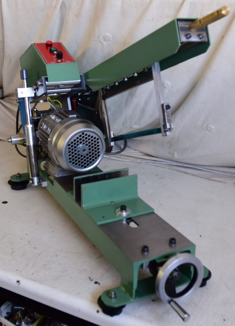
                  The base is a piece of 150mm x 75mm x 8mm channel iron, shapered flat and milled for the vice, etc. The saw frame slides are 18mm Hex, steel for the fixed and brass for the reciprocating frame. The slides pivot on large bearings that are also on the main drive shaft out the gearbox. In the top hat is the 500watt VFD, and the on/off/speed control. Speeds are from about 2 strokes/sec to position the frame when checking stroke length (inching..) up to 130 strokes/sec.

                  ready to cut.jpg

                  Views with all guards in place.

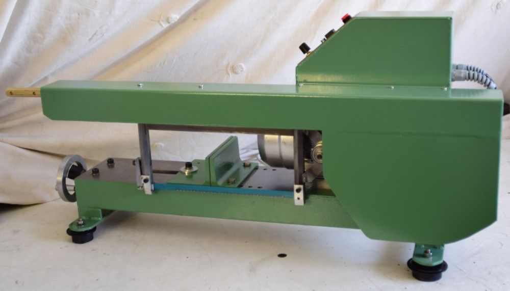
                  right view.jpg

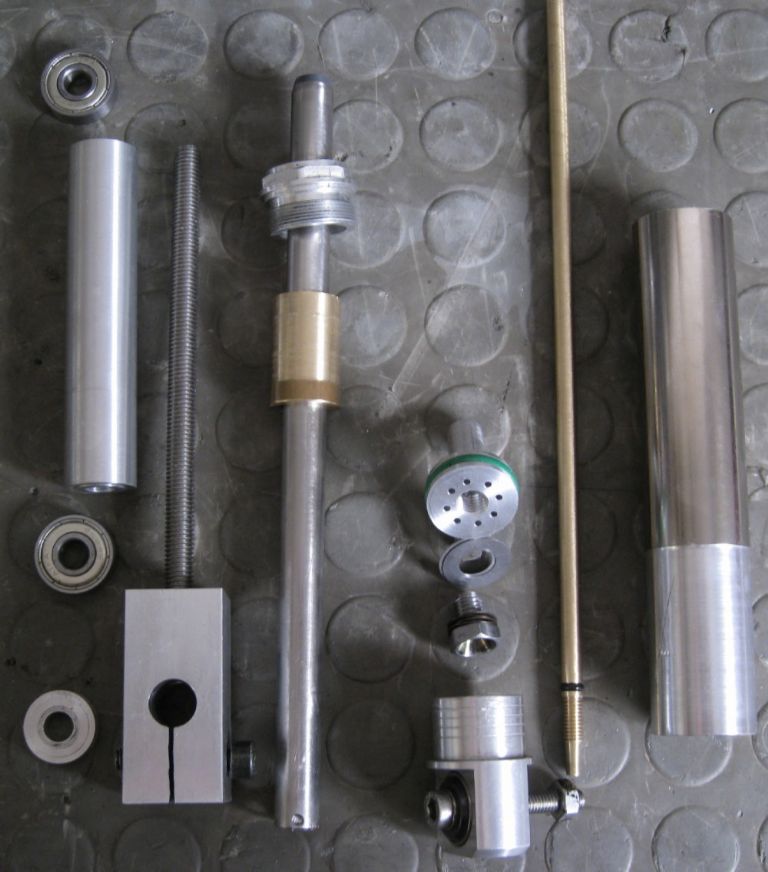
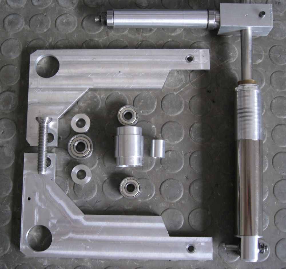
                  The hydraulics are seen here – The tube (right) from an old mountain bike front shock

                  hydraulic system.jpg

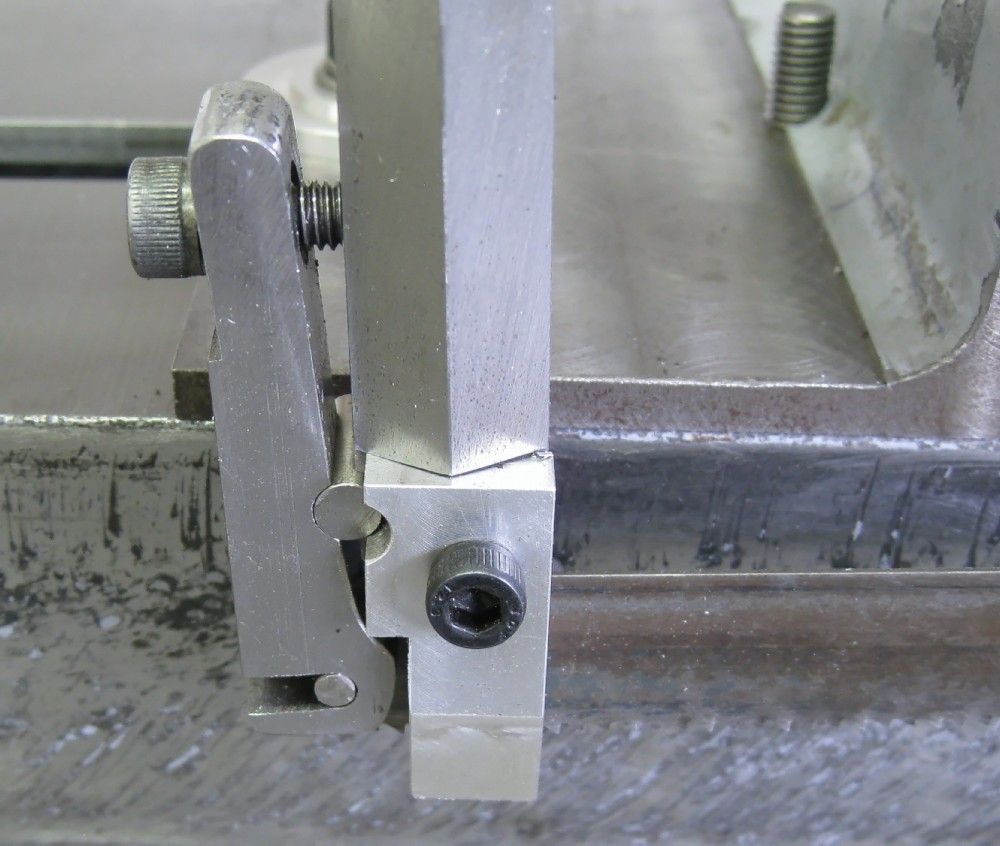
                  This is the cam activated blade lifter during the return stroke – worked OK, but eliminated by appropriate crank moments placement and geometry, with only a damper used. See it working in the video

                  stroke reliever.jpg

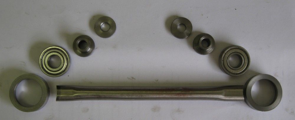
                  The drive con-rod, ready to weld up. The crank has three throws giving strokes of 220mm, 160mm and 80mm, allowing optimal use of the full blade for different stock sizes.

                  crank to weld.jpg

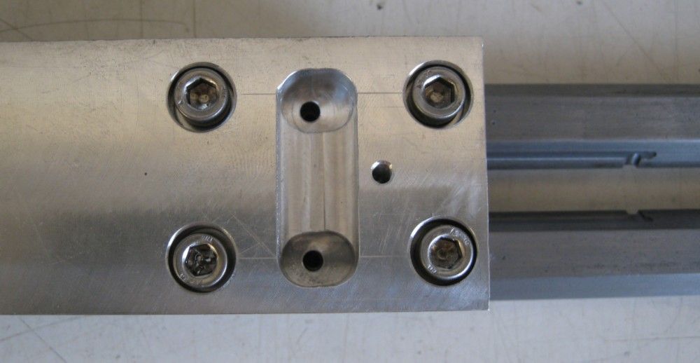
                  The oil distribution grooves in the fixed hex slides – fed from an oil well in the top support – one-shot oiling..

                  oil distribution grooves2.jpg

                  The oil well.

                  top support with oil well.jpg

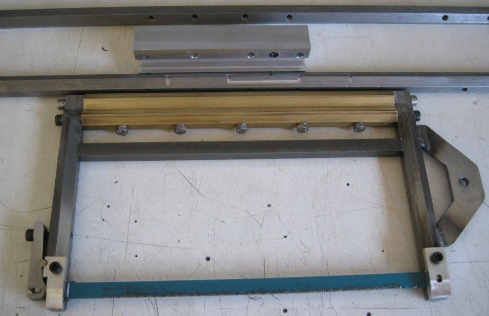
                  The saw frame and slides.

                  saw frame and slides.jpg

                  Blade Tensioner.

                  tensioner.jpg

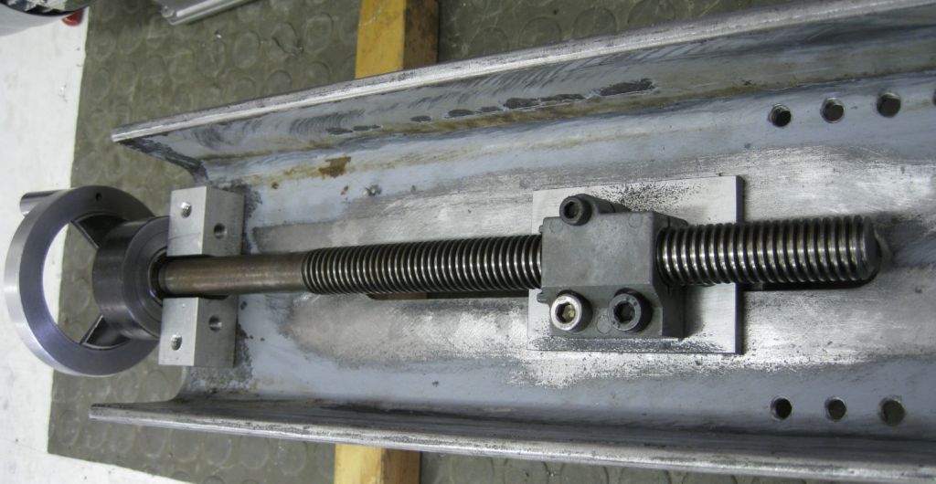
                  The vice/screw – made from an old imperial X leadscrew from and EMCO FB2 mill.

                  vice screw.jpg

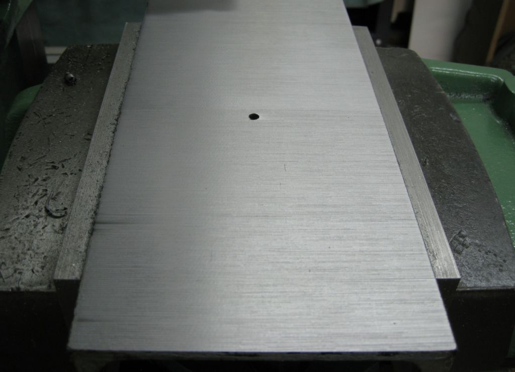
                  The shaper flattening..

                  table shaper flatted.jpg

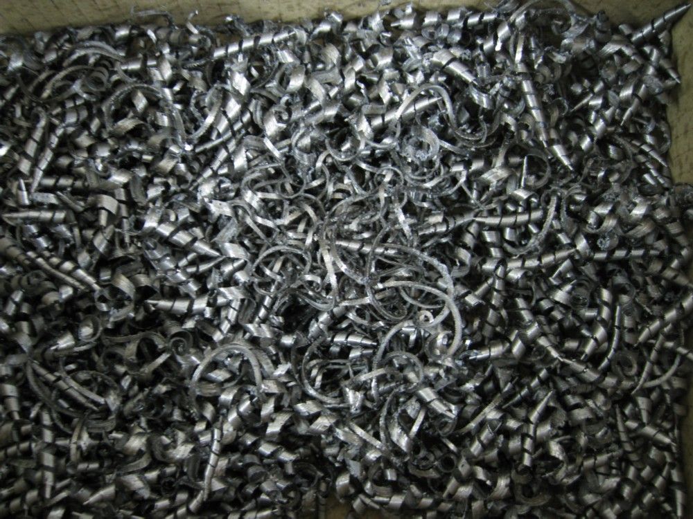
                  And…

                  table shavings.jpg

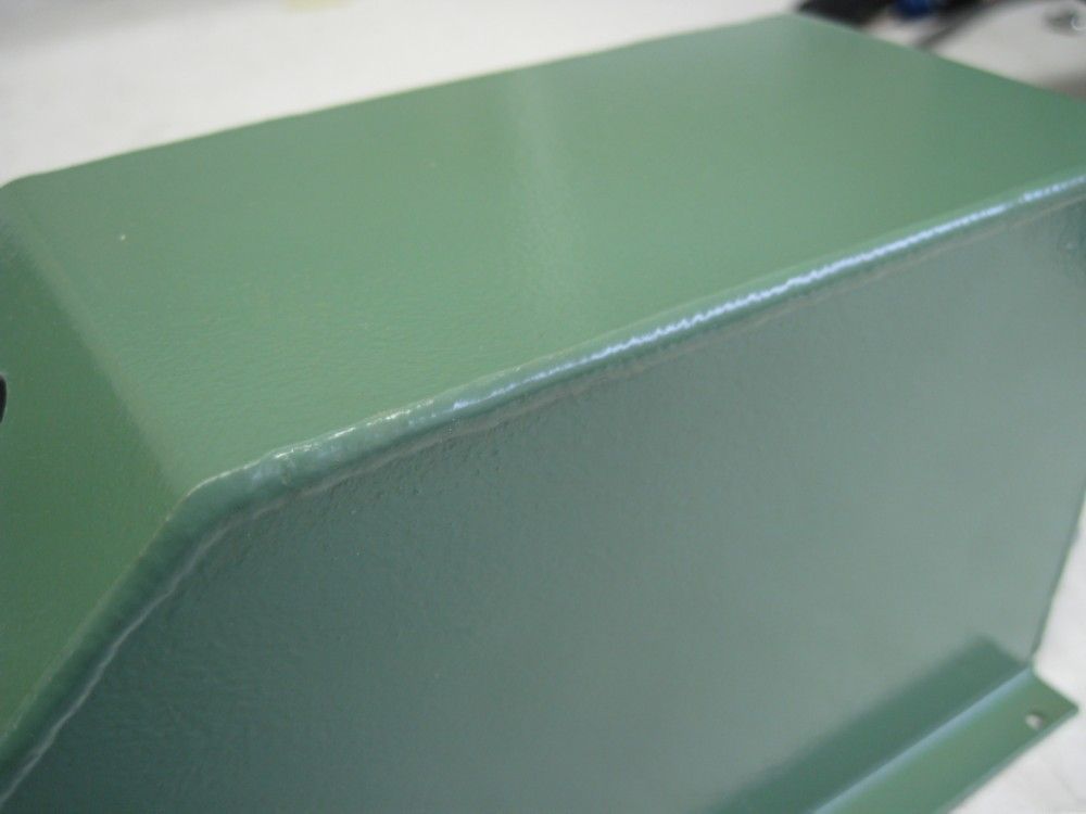
                  The TIG welding on the Ali covers was so good, I just painted over and did not smooth down! ( patting my back..)nice tig weld.jpg

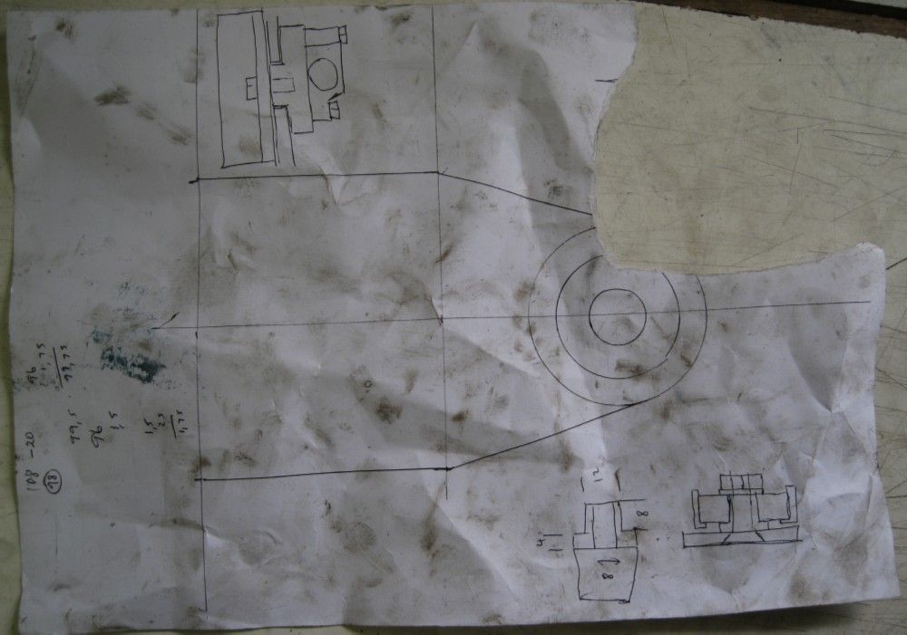
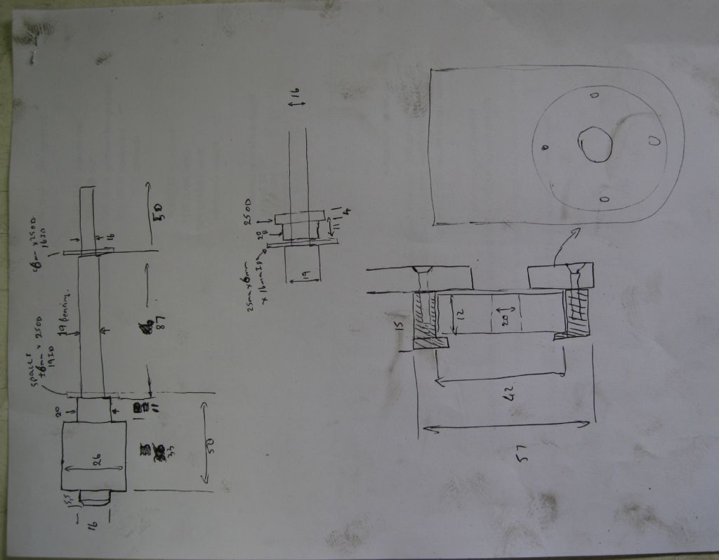
                  All my 'CAD' design drawings for the complicated bits…

                  dwg1.jpg

                  dwg2.jpg

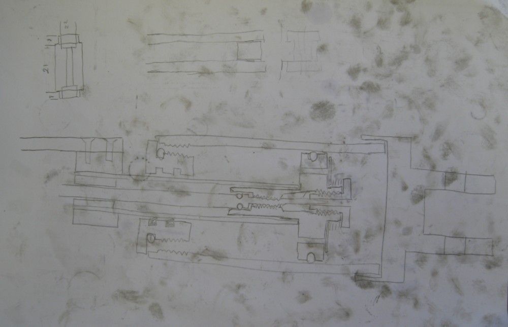
                  Hydraulics..

                  dwg3.jpg

                  A video link below- does not neatly stand on its own, but shows the workings well enough. The blade reliever during return stroke was a trial only really – the cam has a 2mm offset, which through the lever gave a blade raise of 4mm. This needs to reduce to maybe 1mm, ie, cam lift of 0.5mm or so – But the adjustment of the hydraulic drop rate is just to finicky in this mode, and the damper only mode, coupled with proper crank throw moments works best Also, the blade front is 1.5mm lower than the rear mount, and that with correct damping drop rate works very well.

                  **LINK**

                  Took 2 weeks to build, finished on the 1st Jan 2019…And Neil, I was ALSO crimping wires for this on Christmas day!

                  Joe

                  #388824
                  martin perman 1
                  Participant
                    @martinperman1

                    Thats some saw.

                    Martin P

                    #388898
                    Joseph Noci 1
                    Participant
                      @josephnoci1

                      Thanks Martin..

                      After building the saw I decided I had better do something about all my poor condition drill bits..

                      I have a neat T&C grinder that does drills very well, but is a huge pain to setup, so tends to not be used for drill sharpening. I always thought a jig such as the one in March 2000 (issue 64) MEW was a good idea, and when I got hold of a square block 5C collet holder I decided this morning to knock up a similar adaptor for my grinder.

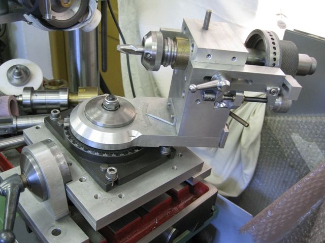
                      This is the universal tool head on my grinder – does all, but requires a lot of set up.

                      toolholder-1.jpg

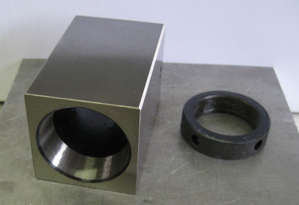
                      The 5C collet block

                      collet block and ring.jpg

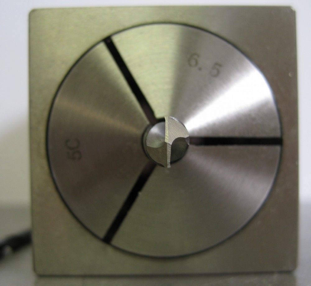
                      With a sharpened drill still inserted

                      drill ground.jpg

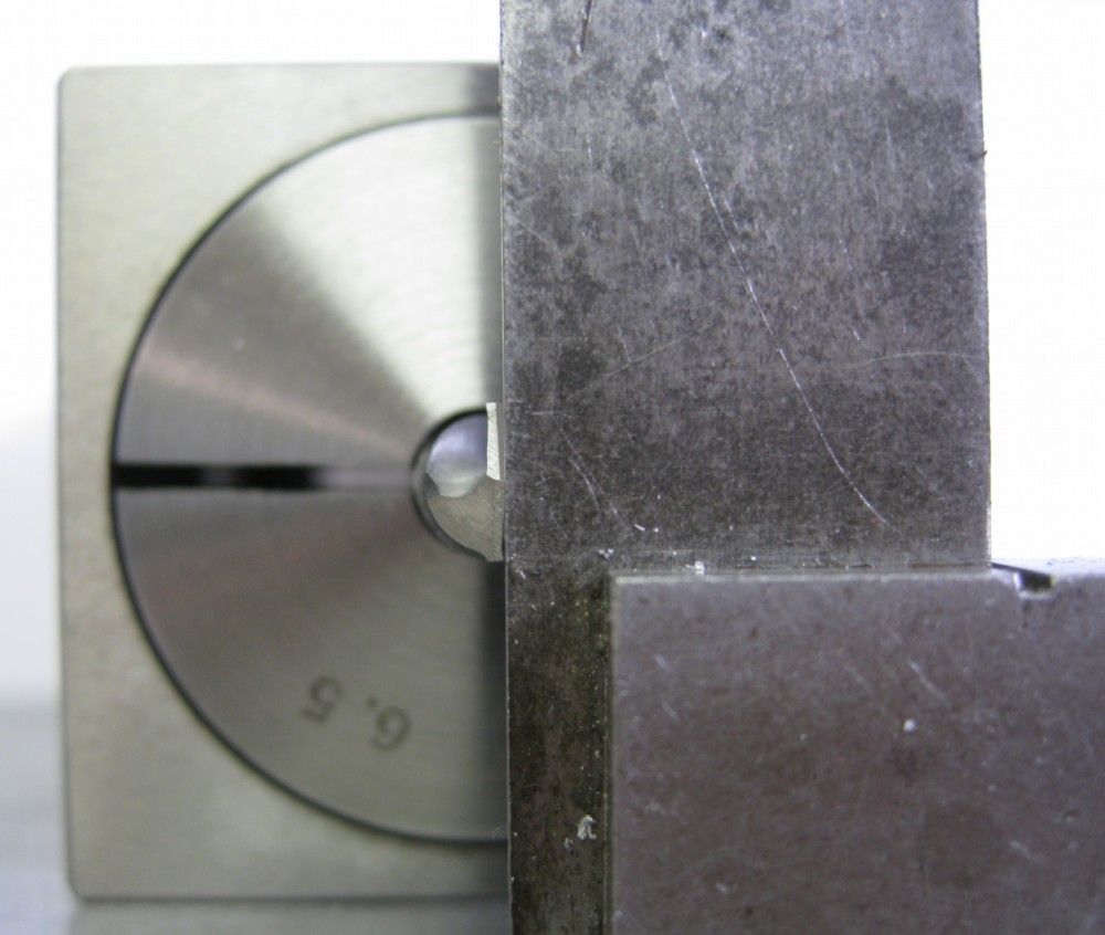
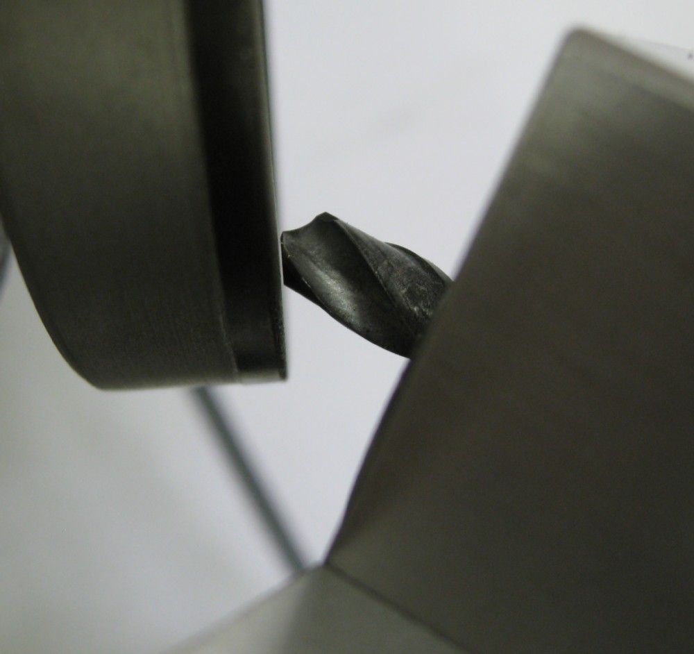
                      Method of aligning the drill edges

                      drill edge alignment.jpg

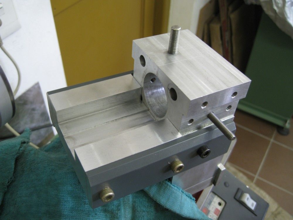
                      The universal tool head with extraneous removed and a fabricated Collet block table fitted

                      collet block table.jpg

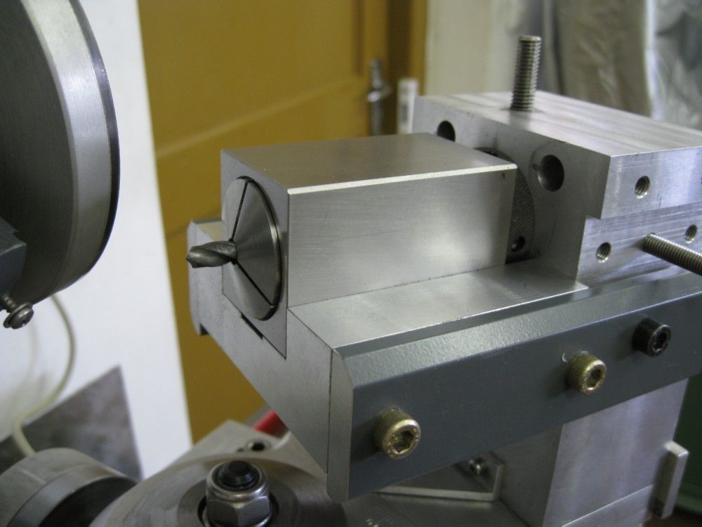
                      Collet block with drill in place. The block is heavy and stays in place with the tilt of the table for the relief angles.
                      collet block inserted.jpg

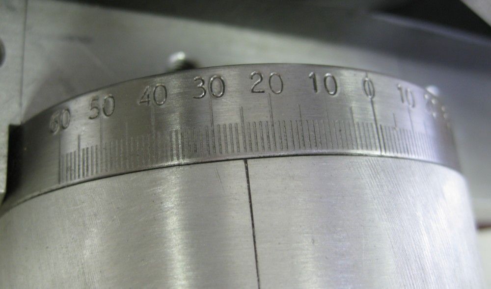
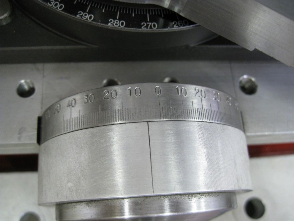
                      25deg secondary relief set

                      25 deg secondary relief.jpg

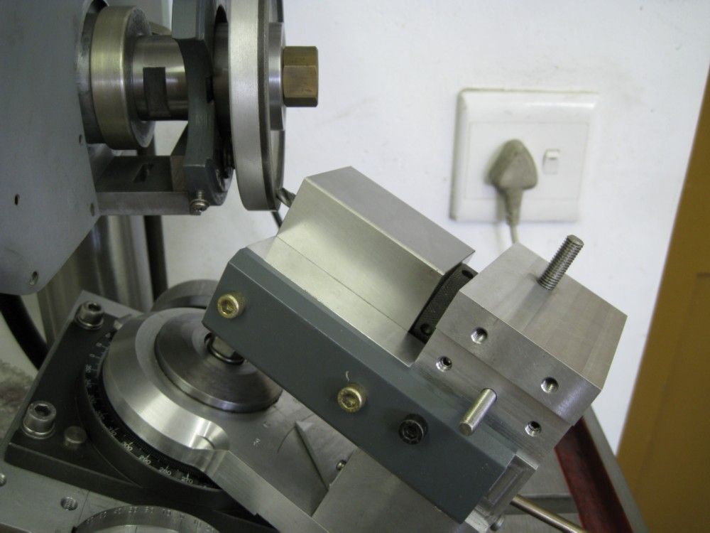
                      Grinding secondary relief.
                      grinding secondary relief.jpg

                      secondary grind at wheel.jpg

                      5deg primary relief set

                      5 deg primary relief.jpg

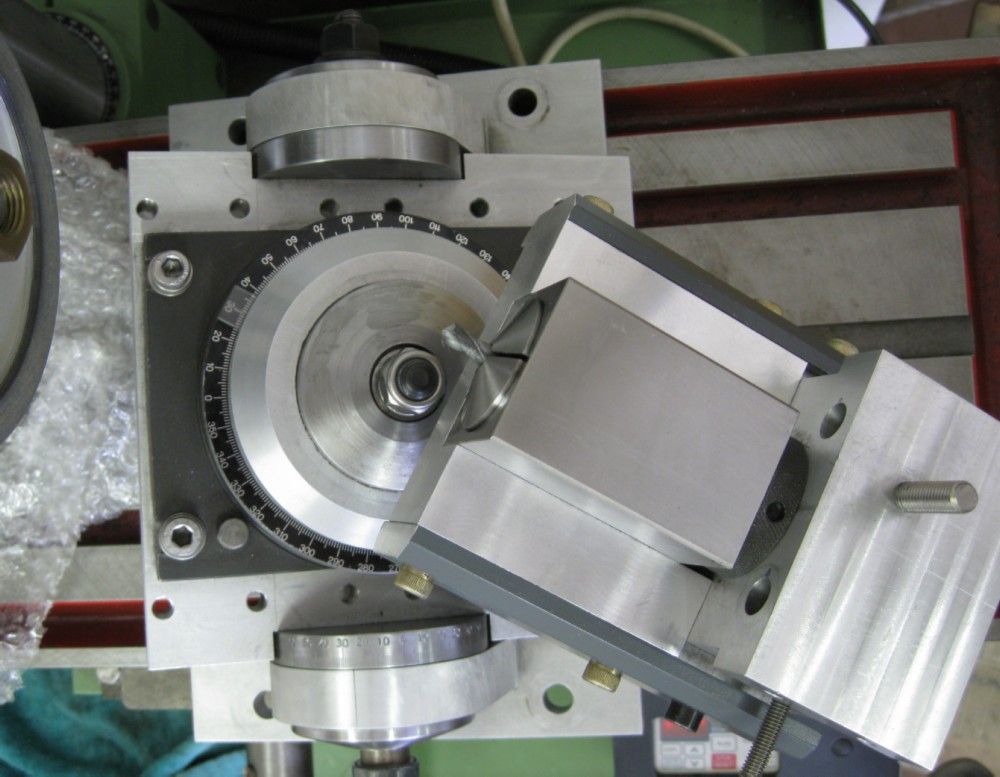
                      View of motion tables from above.

                      the motion tables.jpg

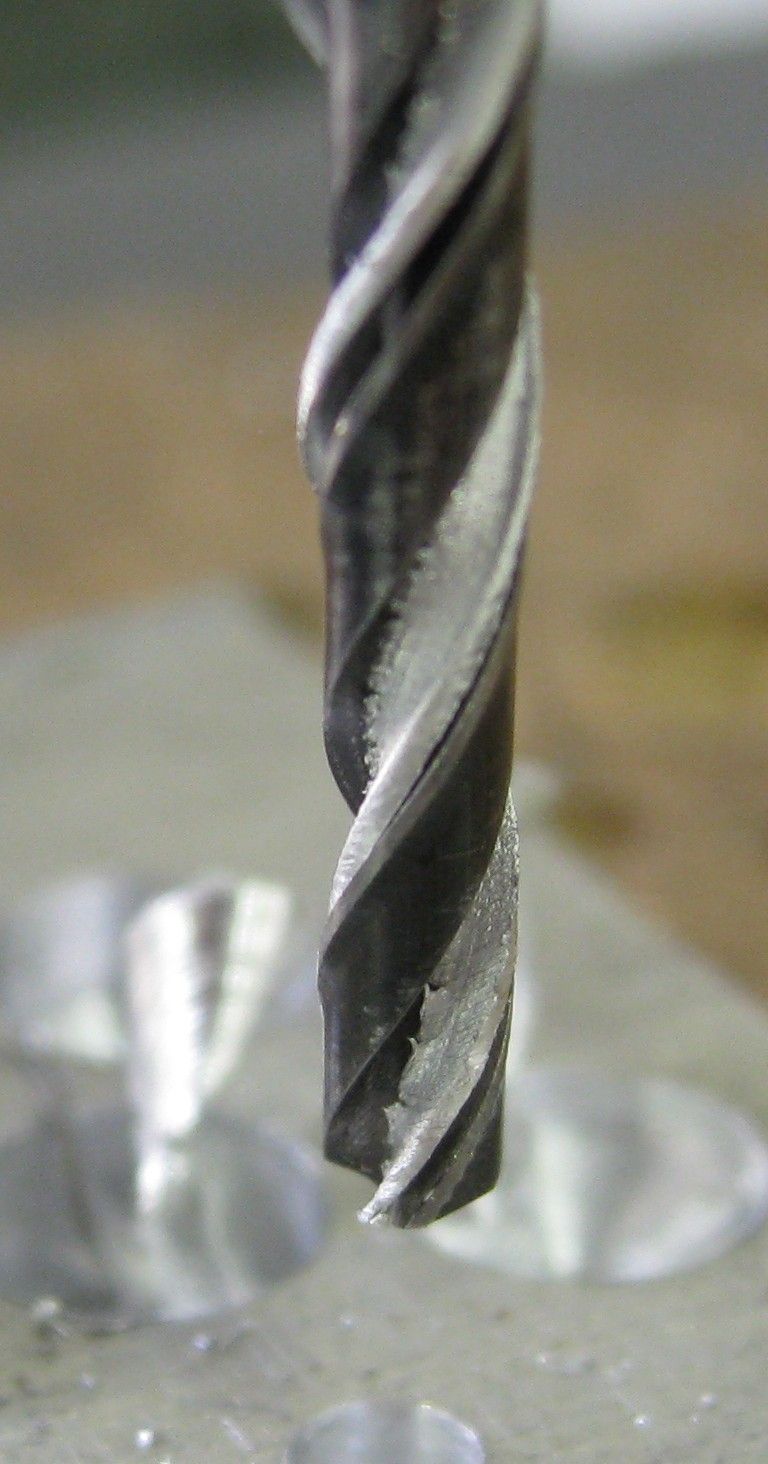
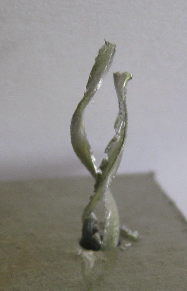
                      6.4mm drill swarf – not to unbalanced..

                      6.4mm drill swarf.jpg

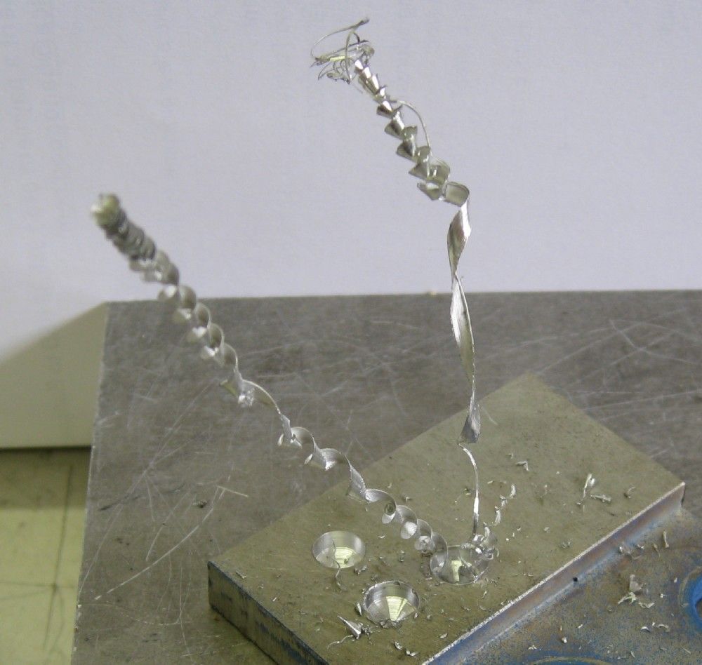
                      3mm drill swarf. ( poor, soft and string Ali..)

                      3mm drill swarf1.jpg

                      3mm drill swarf2.jpg

                      Joe

                      #388900
                      Paul White 3
                      Participant
                        @paulwhite3

                        Joe,

                        Did you really mean 2 and 130 strokes/sec. I know you build fast but HSS blades must be essential!

                        A very neat product at any speed.

                        #388904
                        Joseph Noci 1
                        Participant
                          @josephnoci1

                          Hello Paul! A good New Year to you Sir!

                          Yes, become bored over the holidays, so got stuck in..And yes, 2 to 130 strokes/s. When the stroke is set to 80mm for example, I could really do with even around 150 strokes/s or faster..At the 220mm stroke, 100 strokes/s is comfortable. I do use HSS blades, but I also cut blade lengths from bandsaw blade stock and drill the tension pin holes with a carbide drill – those blades work even better, as I can easily do down to 12 teeth/inch which is great for thicker Ali stock.

                          Anyway, it was a lot of fun in the making.

                          Nice to hear from you!

                          Joe

                          #388906
                          Paul White 3
                          Participant
                            @paulwhite3

                            Joe,

                            I should have guessed, did not consider stroke variation, making an even more impressive build.

                            Looks like a busy year, 2 days into it and 2 projects finished

                            .Paul

                            #388911
                            JasonB
                            Moderator
                              @jasonb

                              Joe, if you are using a 100:1 gearbox then you would need the motor to be running at 780,000 rpm to get 130 strokes per second are you sure it is not strokes per minute, even then its 13000rpmcrook Or have you used the gearbox to increase things rather than reduce?

                              #388925
                              Joseph Noci 1
                              Participant
                                @josephnoci1

                                As usual, Jason is Wide Awake! I have too many bits on the go here…The 100:1 is for the gearbox on a motor I am using for another cheese curd stirrer for my good wife – and that one is giving me a headache, and so was on the brain, so to say!

                                Sorry, to set things straight – The saw's motor is 1345RPM @ 50Hz ( according to its descriptor plate). The gearbox is a Varvel 15:1 box, and the speed should have been in STROKES/min !! Seems I got most of everything wrong..

                                I think I'll just back off and try again next year….

                                Should really edit that post 'cause that is plain crappy posting..

                                Joe

                                #388946
                                daveb
                                Participant
                                  @daveb17630

                                  I wouldn't mind getting it all wrong if my jobs turned out like that.

                                  I like the drill jig, just what I need for my Clarkson.

                                  Very nice work Joe!

                                  Daveb

                                  #388970
                                  Joseph Noci 1
                                  Participant
                                    @josephnoci1

                                    Daveb,

                                    Since the Clarkson has both table traverse and feed, you would not need anything more than what I have implemented – just a firm tray/guide to hold the square collar block and a means of setting azimuth and elevation angles. Since the drill tip included angle can be fixed, that one is easy to do, and then a means of setting 25deg and 5deg ( or whatever takes your fancy) for the primary and secondary facets in the remaining plane is all that is needed.

                                    I was very pleased with the accuracy of the collar block – it is a chinese block and was inexpensive, but is ground parallel to within plus/minus 0.002mm across all flats! Fitting a 10mm 5C collet with a 10mm carbide rod in the collet and placing the block flat on a granite block I find less than 0.006mm variation with a height gauge and dial indicator between granite surface and top of the carbide rod, on all 4 block faces. Part of that variation will also be from the collet, so all together not bad at all.

                                    The 5C collet also offers more contact length across the drill flutes which seems to give better drill location on smaller drills ( sub 3mm) than I was obtaining with ER20 collets.

                                    I appreciate the ease of removing the block from the receptacle and being able to quickly inspect the tip grinding progress, and then replacing the block with no loss of register.

                                    What I need to do is make up some sort of optical/magnifying aid to better align the drill cutting edges parallel with two sides of the block, especially the smaller drill. Maybe a small video camera in line with the drill bit tip, and projected onto a PC screen with a cross-hair overlay. Problem with that is that it starts to become too complicated again to get all the bits out, connected and working, before I can sharpen a drill bit…A monocular magnifying eye piece in line would work fine, but I have few skills in that dept – and no optics or lenses to play with!

                                    Joe

                                    #389012
                                    David Standing 1
                                    Participant
                                      @davidstanding1

                                      Joe

                                      I am now at the point where I recognise a photo that is clearly your work before I even see who has posted it! yes

                                      #389019
                                      Jeff Dayman
                                      Participant
                                        @jeffdayman43397

                                        Joseph – re the covers TIG welding – you keep going like that and there will be grinder disc factories shutting down!

                                        Great work, well done.

                                        #389052
                                        Joseph Noci 1
                                        Participant
                                          @josephnoci1
                                          Posted by David Standing 1 on 02/01/2019 22:22:37:

                                          Joe

                                          I am now at the point where I recognise a photo that is clearly your work before I even see who has posted it! yes

                                          Mmmm, David, methinks I need to change the colour that I paint things..

                                          Joe

                                          #391239
                                          Ian McVickers
                                          Participant
                                            @ianmcvickers56553

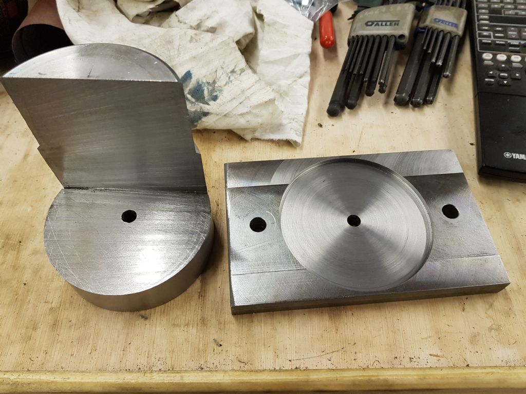
                                            I'm in the middle of making a version of the upgraded universal head for the Clarkson MK1 Tool Grinder as shown on the bedroom workshop site. Base plate has been milled to size and a recess cut to accept the upper part. A centre line was engraved across the plate as well but it doesn't show up too well on the photo. Upper part turned to size at 95mm diameter and 110mm high then cut in the bandsaw, about 30 minutes worth of cutting. Hopefully at the weekend I will get some time in the shop to finish milling it and possibly get a scale engraved around the bottom edge.

                                            Universal head_1.jpg

                                            Universal head_2.jpg

                                            #391621
                                            JasonB
                                            Moderator
                                              @jasonb

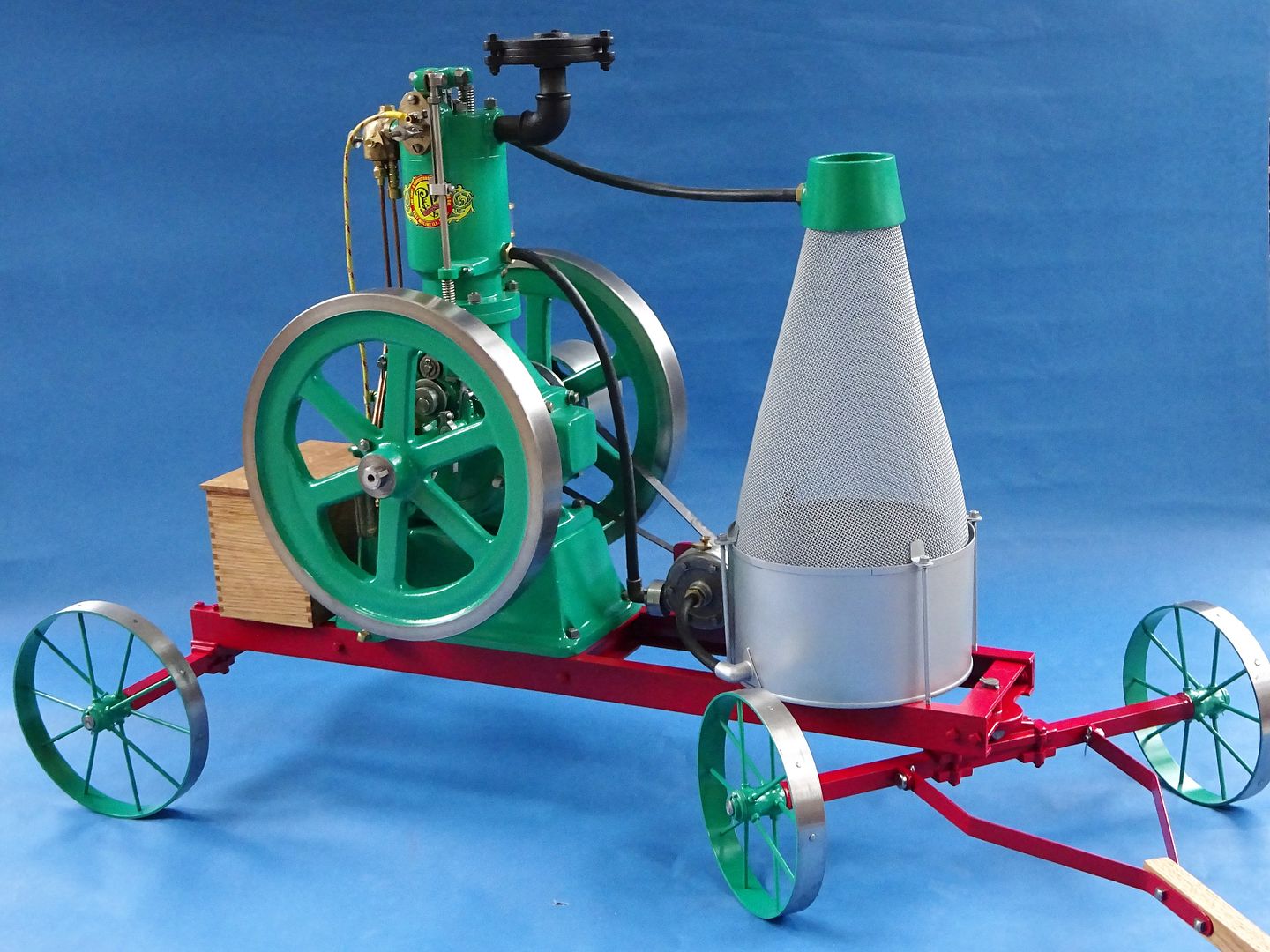
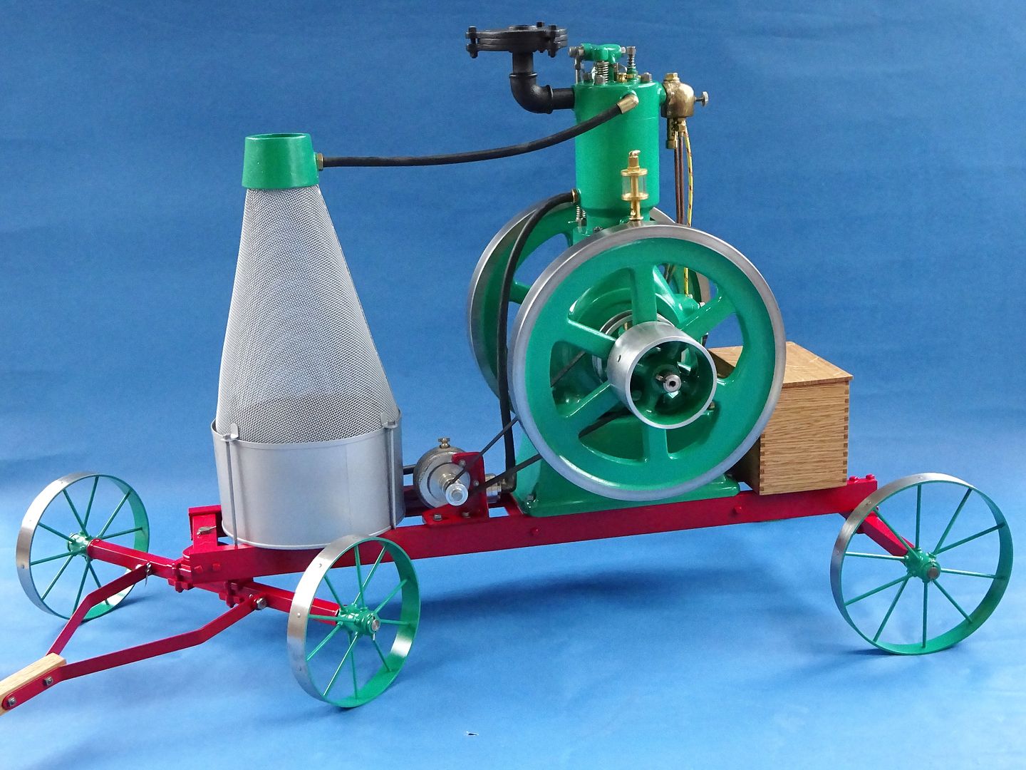
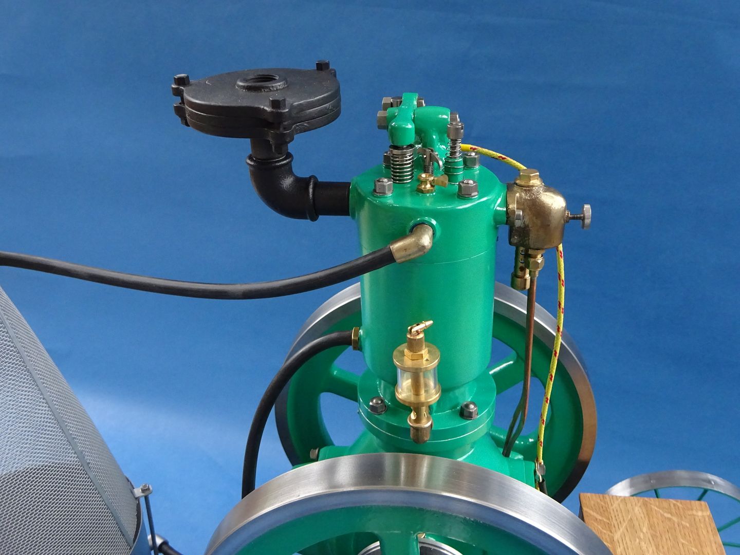
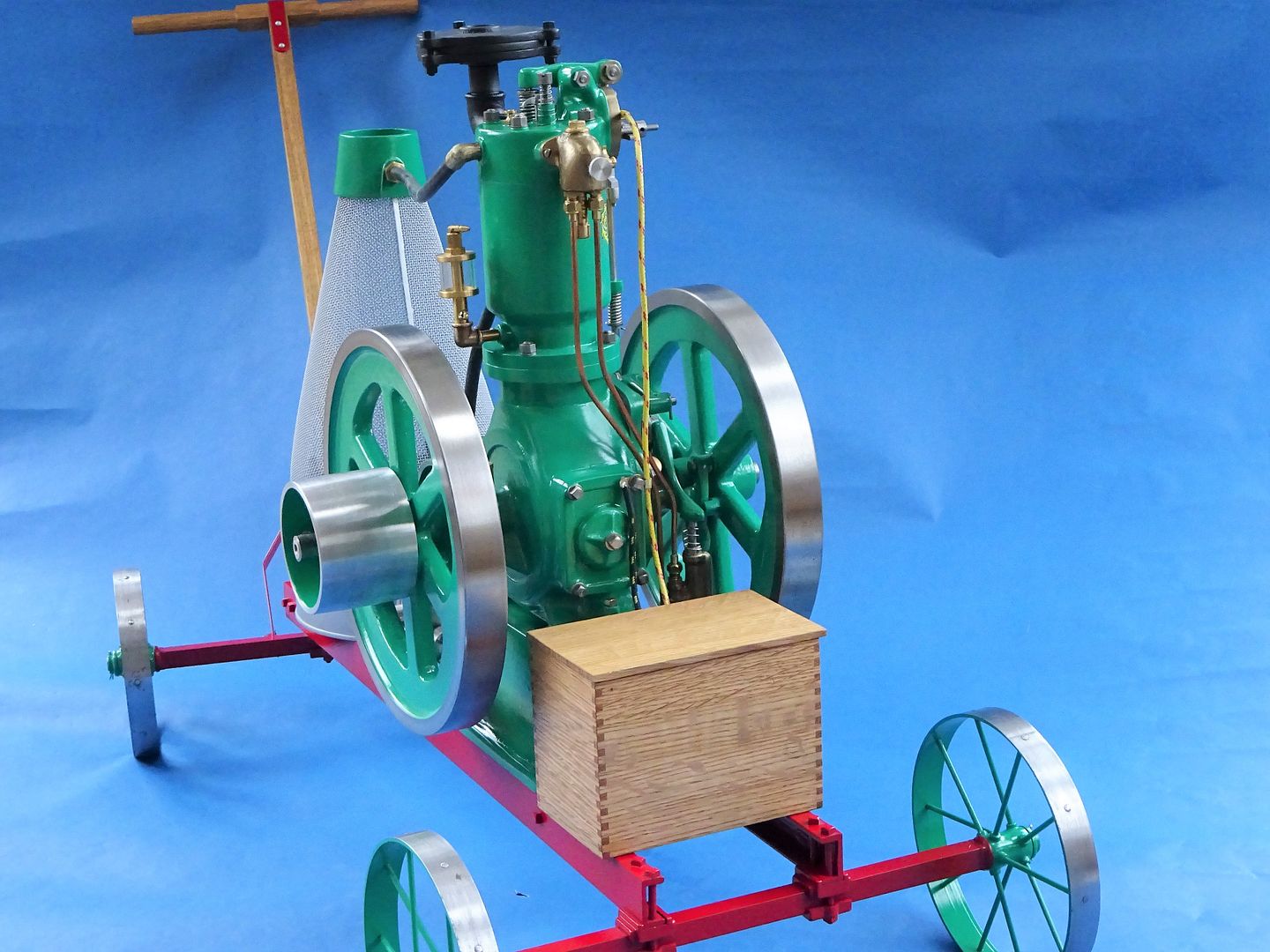
                                              After letting the paint harden off for far longer than it really needed I thought it was about time to see if I could remember how it all went back together, I think this looks about right and there were no bits left over blush

                                              [img]

                                              It is not quite as lively now it is back together though that may be due to having to fit a new ring as I broke one during assembly though compression seems reasonable. I have not got the governor latching in this video as it does not need it at these speeds. Hopefully with a bit more tinkering it will liven up and the governor can be set to work.

                                              #391628
                                              martin perman 1
                                              Participant
                                                @martinperman1

                                                Jason,

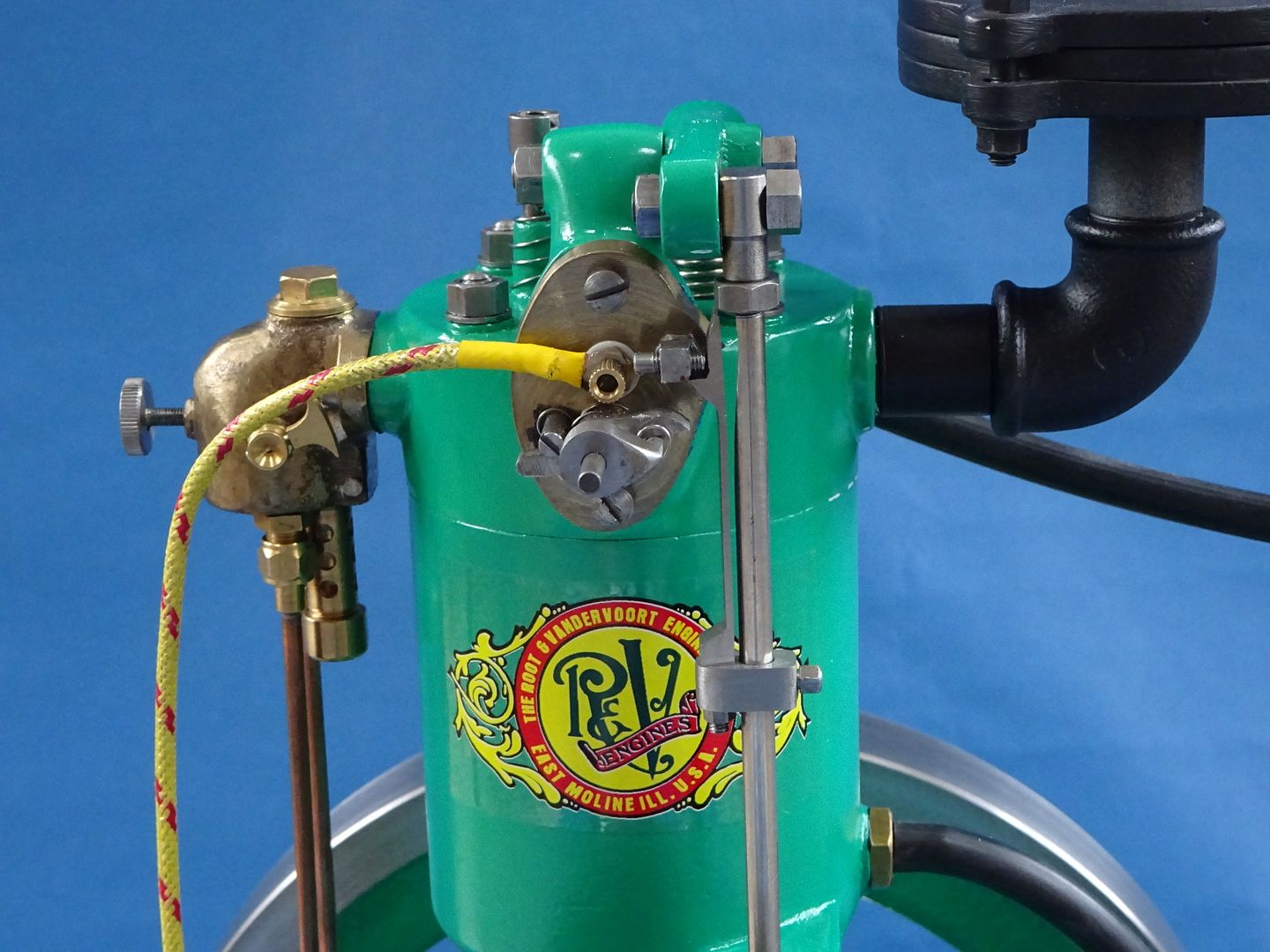
                                                I can only describe that engine as beautiful, does the screen cooling work as well and how much time did you take timing the ignition trips, I've watched owners of full size engines spend ages trying to get full size ones working properly, Vanderoot verticals are few and far between in the uk but there are a lot of open crank horizontals about.

                                                Finally was it a set of castings or made from scratch.

                                                Martin P

                                                #391635
                                                Ron Laden
                                                Participant
                                                  @ronladen17547

                                                  Oh I really do like that and some lovely engineering, did you cut all those corner joints on the wooden box by hand.

                                                  You know me Jason, what type of engine is it, how does it work and Martin mentions screen cooling..?

                                                  Excellent.

                                                  #391637
                                                  martin perman 1
                                                  Participant
                                                    @martinperman1

                                                    Ron,

                                                    Screen cooling was a method favoured by the Americans to cool the engine water, the pump that the engine is driving pumps the water through the engine and it comes out of the pipe at the top of the cone in a spray pattern down the screen, because of the surface area and the surrounding air it cools the water which collects in the tank at the bottom to go around again, engilsh manufacturers tended to rely on large tanks of water which evaporated off the heat.

                                                    As its Jasons engine I will let him describe how it works.

                                                    Martin P

                                                    Edited By martin perman on 17/01/2019 22:06:39

                                                    #391666
                                                    JasonB
                                                    Moderator
                                                      @jasonb

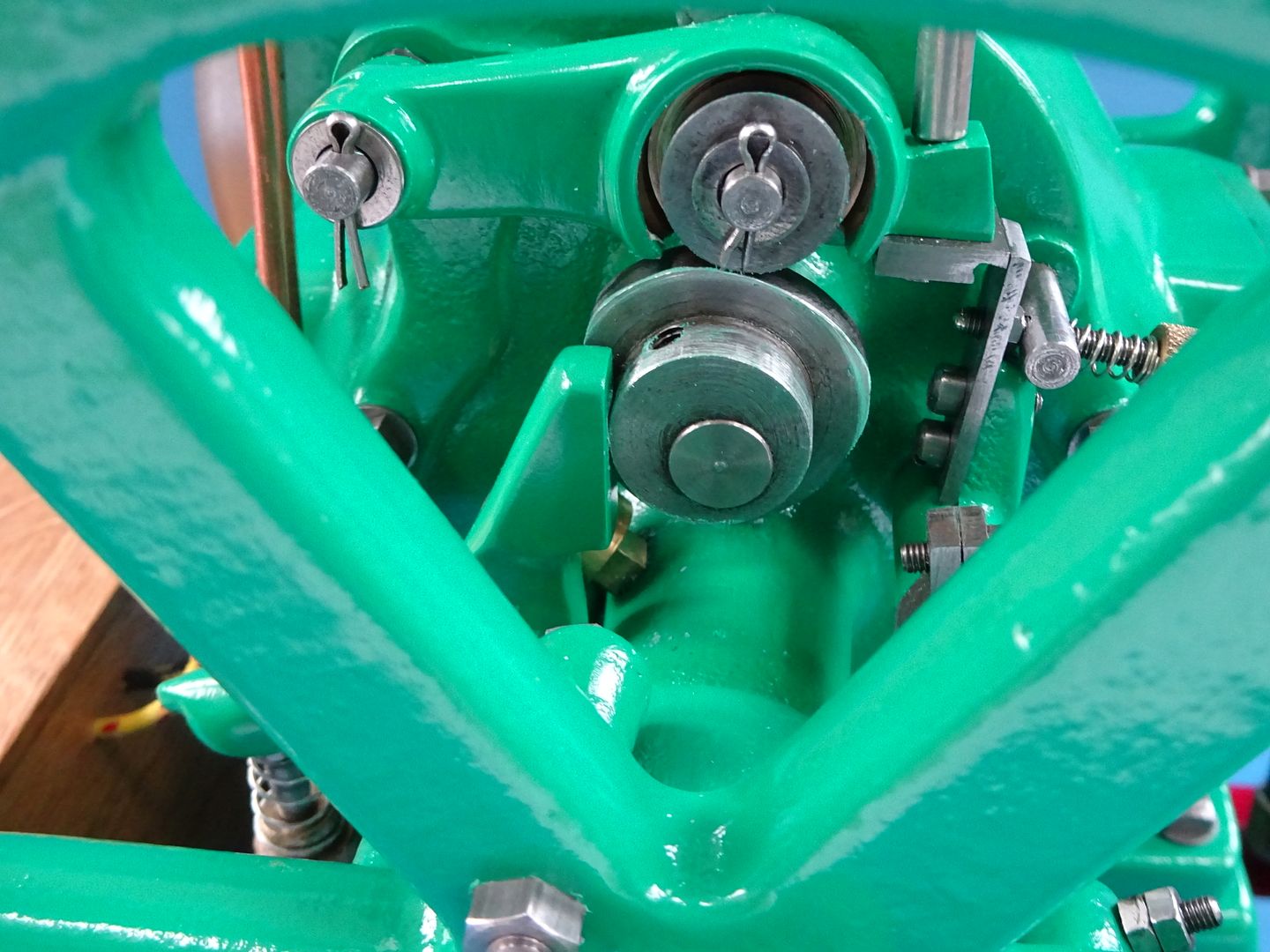
                                                      Martin, I have spent a lot of time fiddling with the ignitor trip, it does not have the same adjustment methods as some or the horizontals that I have built so is a right pig to get working anywhere near right.

                                                      The pump does work when I have tried it with a cordless drill, may hook it up and run some water through it once the engine is running well though they don't get too hot and can be run for several minutes dry.

                                                      It is from a casting kit but the cart is scratch built. It came to me as part made with all the larger items having been done, there were some major issues such as a wonky crankshaft and the top of the crankcase was machined very out of true so the cylinder was leaning sideways

                                                      Ron, this is how I did the joints.

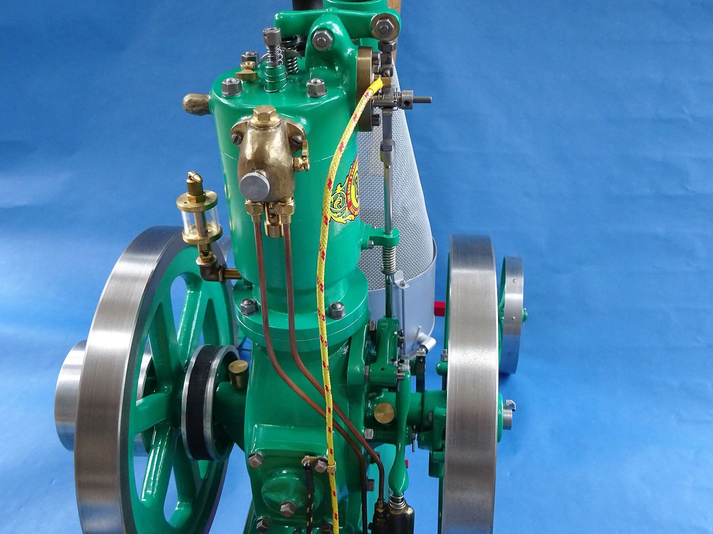
                                                      The engine would be classed as a Vertical Hit & Miss Engine. vertical as it stands upright rather than the more common layout with a horizontal cylinder.

                                                      The hit and miss bit refers to how the speed is controlled (not set working in that video) There is a pivoting weight on the inside of the flywheel that swings out as the engines speed increases, as it rotates round it pushes a lever that will latch the exhaust pushrod in the open position which means there will be no compression and the engine won't fire which is the miss part. As the speed drops the latch will release and close off the exhaust so the engine will then be able to draw in air/fuel as there will be a vacuum when the piston goes down – compressed – fire which is the hit part. When the engine is running under load it may not get up to a fast enough speed to miss so will fire on each stroke, if the load is taken off then it will start to miss. If you watch my video of it's stable mate you can see that the exhaust rocker arm only lifts clear of the valve about every 3rd or 4th cycle.

                                                      And before it was painted you can see me manually making it miss by holding the rocker down about half way through. The vertical should be running more like this.

                                                      Otherwise it is just a 4-stroke engine, the only slight difference is that the inlet valve does not have a mechanical opening such as push rod and rocker. It just has a weak spring which is just enough to hole the vale closed but on the intake stroke the vacuum in the cylinder will open the valve letting the air/fuel mix in.

                                                      As the carb is at the top of the engine this one also has a fuel pump down on the left hand side – the whole bottom casting is the fuel tank – which constantly pumps fuel to the carb with any excess flowing back down to the tank under gravity.

                                                      It does not use a spark plug but has what is known as an ignitor. Basically a set of moving contacts that are within the head. As the exhaust pushrod moves up it has a lever on the side which closes the contacts and allows electricity from the battery to flow around a circuit containing a low tension coil. As the rod goes up more it moves away from the ignitor and allows the contacts to open but the energy in the coil causes a spark to jump across the gap and this is what ignites the fuel. They are very tricky to make with lots of small parts and torsion springs to be wound.

                                                      As said by Martin cooling is buy water being pumped into the bottom of a water space around the cylinder then into voids in the head before overflowing down the wire mesh which cools the water before it gets pumped round again.

                                                      J

                                                    Viewing 25 posts - 1 through 25 (of 261 total)
                                                    • Please log in to reply to this topic. Registering is free and easy using the links on the menu at the top of this page.

                                                    Advert

                                                    Latest Replies

                                                    Viewing 25 topics - 1 through 25 (of 25 total)
                                                    Viewing 25 topics - 1 through 25 (of 25 total)

                                                    View full reply list.

                                                    Advert

                                                    Newsletter Sign-up