ALBS 2S Dovetail Vertical Slide Dovetail repair

Advert

ALBS 2S Dovetail Vertical Slide Dovetail repair

Home Forums Work In Progress and completed items ALBS 2S Dovetail Vertical Slide Dovetail repair

Viewing 12 posts - 1 through 12 (of 12 total)
  • Author
    Posts
  • #311870
    Joseph Noci 1
    Participant
      @josephnoci1

      The last bit of painful work left in the refurb of my shaper is the repair of the broken vertical slide dovetail.

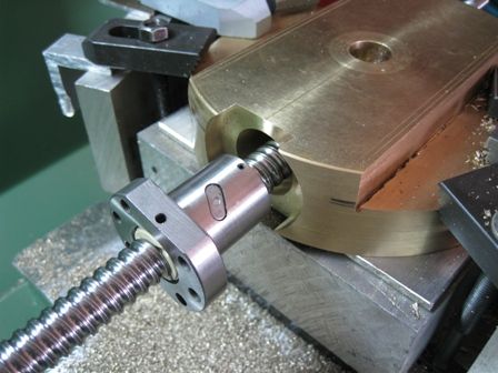
      I have cut off the broken dovetail section from the ram head, and machined the head flat. I obtained a 210mm diameter section of Phosphor bronze, 40mm thick, and will machine the new dovetails into this, and then bolt this to the Ram head. The Slide leadscrew was also badly bent in the last owners crash, so while about it, since I am adding Stepper NC control to the Z axis, I decided to fit a 16mm ball screw to the slide.

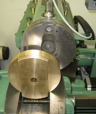
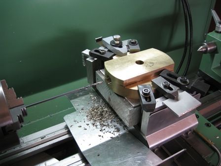
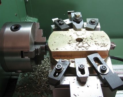
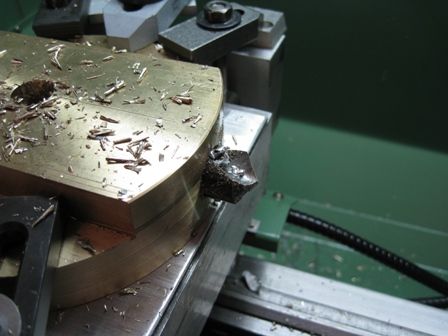
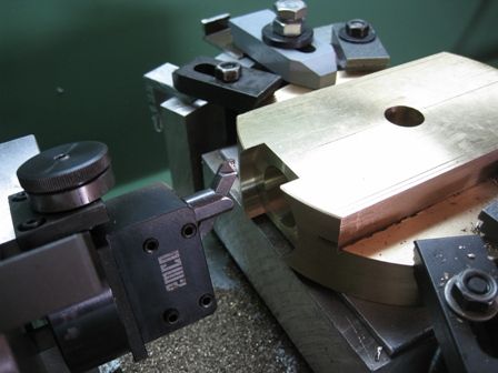
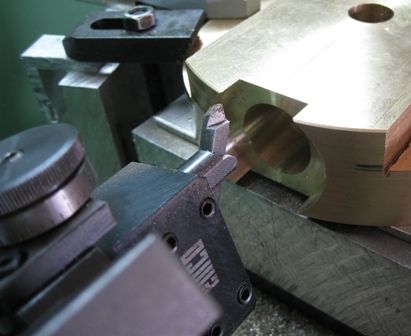
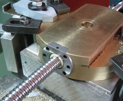
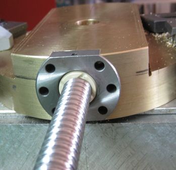
      The bronze was machined on diameter to fit the Ram head, and made flat. The dovetail area marked out and the excess material cut out on the bandsaw. The section was then mounted on the lathe cross slide to drill out the leadscrew through-hole, and bore out the ball nut mounting cavity. The thru hole is 20mm, and a snug fitting, long 20mm bar will fit in this hole to align the section on the mill when ready to cut the dovetails.

      The original vertical slide dovetails are 55degree, and the cutter I could get (65mm diameter!) is 60 degree, so I will first open up the slide to 60degree on each dovetail, and then measure up and cut the dovetails in the matching bronze part.

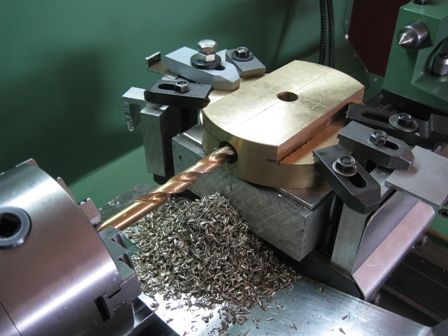
      I must say, I have read all sorts of horror stories about machining PhBronze – grabs the drill immovably, siezes on Taps, etc – this was a breeze! taking care on the drill break-through was needed, but the 20mm drill , with a 6mm pilot hole, followed by 16mm, then the 20mm, went through no problem.

      I have a question – maybe silly to ponder on, but..

      The bronze section is to be bolted onto the cast iron Ram head with 4 x M12 CSK Cap screws. These take no load during the cut stroke, so no problem there. But, is there a sensible preference to put the threads in the bronze, or in the cast-iron head?, ie, Bolt from the front or the rear??

      Pics of the doings..

      This shows the bronze section and how it will fit ( bolt) onto the Ram head- related to the above question

      dovetail replacement.jpg


      6mm pilot

      pilot drill6.jpg

      16mm next up..

      step drill16.jpg

      20mm all through

      20mm drill all.jpg

      20mm tip breaks through..

      20mm drill tip.jpg

      Boring the Ballnut cavity

      ballnut outer boring.jpg

      ballnut outer boring2.jpg

      Ball nut and screw

      ball nut extracted.jpg

      Ball nut snugly in place

      ball nut fit1.jpg

      ball nut end view.jpg

      Joe,,,,

      Edited By Joseph Noci 1 on 13/08/2017 21:03:04

      Advert
      #31176
      Joseph Noci 1
      Participant
        @josephnoci1
        #311887
        Ian P
        Participant
          @ianp

          On one of your album pictures (Head2.jpg) you have drawn on red lines of a proposed location for CSK bolts.

          It looks to me that caphead bolts in counterbored holes could be installed in the opposite direction with tapped holes in the cast iron. I understand that in use these bolts are not particularly loaded but countersunk socket screws have a smaller hex recess which might limit tightening torque.

          Ian P

          #311889
          Joseph Noci 1
          Participant
            @josephnoci1

            Hello Ian,

            My thoughts are prompted by those posted photos – As I am now getting down to details, I was wondering if the original idea is OK or can be improved on, hence my question. The bronze section has plenty of thickness, as does the Ram head, both around 20mm, so counterbored cap screws word work well. I did not consider counterboring as , for some reason, I originally thought of countersinking and the idea just stuck…Odd…I did not consider the smaller hex socket size though , and that's not so good. Thanks for the prompt!

            However, my question was also to understand better if the threads are better done in the bronze or cast iron sections – or would it be much of a muchness..?

            Regards

            Joe

            #311893
            John Olsen
            Participant
              @johnolsen79199

              Probably the bronze would be the better one to have the tapped holes, but since there is plenty of meat there it is not likely to matter much in practice. Drills are liable to snatch a bit in bronze but you can stone the helix side of the cutting edge to remove the rake and get good results. I have never had any problems tapping various bronzes here.

              I look forward to seeing the eventual CNC version of the Alba in pictures!

              John

              #311894
              Hopper
              Participant
                @hopper

                If you use socket head cap screws instead of countersunk, which is a good idea re larger allen key for torquing as said, you might want to put a pair of dowel pins between the bronze and iron parts so the bronze addition does not "walk" around under the repeated load/unload cycles in use and cause slight variations in your cut depth, which could get frustrating. The necessary clearance between the bolt shanks and the holes could allow this movement if the parts are not dowelled.

                I wouldn't assume the bolts take no load during the cut stroke, because the tool usually hangs down below the bottom of the ram so there is load, but a twisting moment leveraged from the tool tip and pivoting on the bottom point of contact between the bronze section and the CI ram body. At the point of initial contact, I would imagine there could be a fair loading on the top bolts.

                #311899
                Joseph Noci 1
                Participant
                  @josephnoci1

                  Thank You for all the comments and suggestions.

                  Hopper, thanks very much – Your comments are enlightening. I did not even consider the twisting moment – and it is quite obvious (once someone tells you..)! The fastening does merit some more thought. I had originally thought of bonding the two parts together with Loktite but maybe pinning is better.

                  Counterboring the bronze for socket heads does worry me a bit – I do not have proper counterbore cutters, but have used end-mills to that mostly anyway – however, whatever the counterbore tool, it is scary doing this in the small EMCO FB-2 mill – an M8 screw needs a 14mm counterbore; an M10 needs 17mm and the potential for tool snatch is great – Not sure if the mill head rigidity is good enough to prevent snatch with normal head downfeed – we will no doubt find out..I am reluctant to stone away the cutting edge of a good, large endmill..

                  Thanks again to all for the helpful info!

                  Joe

                  #311920
                  malcolm wright 1
                  Participant
                    @malcolmwright1

                    You could use a drill for the counterpart and just use an end mill to flat bottom the hole

                    #311930
                    Ian P
                    Participant
                      @ianp

                      Joe, regarding counterboring, why not do each bolt hole on the rotary table?

                      I recently counterbored twenty holes for some 14mm wheel bolts, these were 25mm diameter and 45mm deep (in aluminium fortunately) and I used a long 12mm endmill with the part centred on a spigot on my lash-up 'hand turned' rotary table (no worm etc).

                      I made the table from a VW front wheel hub (wheel flange integral with bearings) the original wheel spigot is turned off and the resulting flat face sits on the mill table. The bearing bore is 30mm (I think) and a shaft with flange has a 250mm disk of aluminium which I drill, or drill and tap, to suit whatever needs to be mounted so its now getting a bit colander like!

                      My mill is an Emco Mentor so weedier than an FB2 but copes well with cutters up to 16mm although I would not use that size in steel.

                      Whilst I sometimes use endmills to create counterbores, its not ideal as the base of the hole is not flat, the rotaty table method solves that.

                      Hopper's comments on the bolt loading and location is very pertinent, also because M12 is quite a coarse pitch I would definitely use some threadlocking device.

                      Out of interest, I now have a 6 speed FB2 column and head that I am considering replacing my 4 speed head with. The Emco mill spindle bearings are a little unconventional and I wondered whether you have converted yours to opposed taper roller races? I once saw details of how the spindle and quill is converted but now cannot trace the article.

                      Ian P

                      #312036
                      Joseph Noci 1
                      Participant
                        @josephnoci1

                        Ian P , that sounds like a good idea! Bit of a pain, aligning each hole with the spindle each time, but worth it I think – I dread that snatch more than the Parting Tool in the lathe…( the Snatch has happened more times than I care for..)

                        Regarding the FB2 bearings – mine are original and in good shape, so no I have never thought of such a conversion. I have no problem with the actual spindle – it is a solid as Gibraltar – but the problem is in the column rigidity – it's not great when doing the heavier stuff. Also, the little bit of play needed in the head-to-column interface ( to allow the head to move up and down) is enough to precipitate a Snatch! The FB2 is very well built, and sturdier than any other round column bench top mill I have seen. I have three of them…One is fully CNC, one fully DRO with power feed on all X and Z, and one manual, but fitted with a heavy Jones and Shipman motor/spindle – used for the heavy roughing…Great pity EMCO did not see fit to use a dovetail column!

                        Will see in the next days how it goes!

                        Regards

                        Joe

                        #312042
                        Ian P
                        Participant
                          @ianp
                          Posted by Joseph Noci 1 on 14/08/2017 20:22:36:

                          Ian P , that sounds like a good idea! Bit of a pain, aligning each hole with the spindle each time, but worth it I think – I dread that snatch more than the Parting Tool in the lathe…( the Snatch has happened more times than I care for..)

                          Regarding the FB2 bearings – mine are original and in good shape, so no I have never thought of such a conversion. I have no problem with the actual spindle – it is a solid as Gibraltar – but the problem is in the column rigidity – it's not great when doing the heavier stuff. Also, the little bit of play needed in the head-to-column interface ( to allow the head to move up and down) is enough to precipitate a Snatch! The FB2 is very well built, and sturdier than any other round column bench top mill I have seen. I have three of them…One is fully CNC, one fully DRO with power feed on all X and Z, and one manual, but fitted with a heavy Jones and Shipman motor/spindle – used for the heavy roughing…Great pity EMCO did not see fit to use a dovetail column!

                          Will see in the next days how it goes!

                          Regards

                          Joe

                          Centering the job for each hole is easy if you can put a spigot in the centre hole of the rotary table. Whether your table has a MT socket or a plain hole will dictate how the spigot is fitted but its not subject to much load so could be a crude as a bit of aluminium bar jammed in, you can mill its OD to suit the bolt holes (which you will have already through drilled).

                          Ian P

                          #312047
                          Joseph Noci 1
                          Participant
                            @josephnoci1

                            Buggerit! Where do you and so many others get all these nifty tricks and ideas from?????? So simple, even I could'nt think of it!

                            Thanks Ian.

                            Joe

                          Viewing 12 posts - 1 through 12 (of 12 total)
                          • Please log in to reply to this topic. Registering is free and easy using the links on the menu at the top of this page.

                          Advert

                          Latest Replies

                          Viewing 25 topics - 1 through 25 (of 25 total)
                          Viewing 25 topics - 1 through 25 (of 25 total)

                          View full reply list.

                          Advert

                          Newsletter Sign-up