CHUKY Flame Licker Build
CHUKY Flame Licker Build
Home › Forums › Work In Progress and completed items › CHUKY Flame Licker Build
- This topic has 42 replies, 10 voices, and was last updated 23 December 2020 at 07:41 by
 JasonB.
-
AuthorPosts
-
13 June 2017 at 19:52 #302455
 JasonBModerator@jasonb
I remember seeing the CHUK range of engines when Graham Corry first posted them on the Alyn Foundry website and quite liked the look of them but as I was engrossed in building my Fowler traction engine at the time did not have the need for more engines.
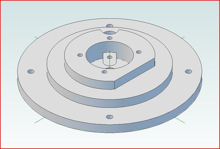
With the demise of Alyn Foundry I had put the engines out of my mind until Andy (Chipmaster on MEM forum) started a build thread on his set of castings which got me thinking about building a flame licker. There are a few designs about but they do all look as though they were made from bar stock which in fact they are! I still liked the look of the CHUK and was able to borrow the build notes that came with the engines, these combined with looking at Andy's engine photos and a bit of artistic license allowed me to come up with the design shown below. Despite what some people said in Andy's build thread if you want to make an engine enough you don't need dimensions on every feature to copy


I have made a few engines recently with a 24mm bore which I find quite a nice size as they are not too big to handle or display and there are no large bits of metal needed that will break the bank. So this engine also has a 24mm bore which makes it about 2/3rds the size of the original CHUK, stroke is 32mm and the flywheel is 102mm dia and also the only casting used but at that size could be fabricated quite easily. I have tried to add a bit of shape to the parts so that they look like they were made from castings rather than make just another barstock engine.
The work is mostly milling or turning from solid although there are two items that will require silver soldering, even then one could probably be done with some small CSK screws if you don't fancy soldering. There are also several parts that need lapping, the flat ones can be done easily enough on a flat surface with fine wet and dry but the cylinder also needs lapping as does the piston.
A big thanks to Andy for posting his original build and help with the build notes and also to Graham Corry for coming up with the engine in the first place and also giving me permission to share my design drawings with the membership so lets start making swarf.
This is a 3D pdf which should allow you to look around the engine design in detail, may need flash
13 June 2017 at 19:52 #31166 JasonBModerator@jasonb13 June 2017 at 19:58 #302456
 JasonBModerator@jasonb
BASE
This can be made from a slice of 75mm or 3" dia aluminium or could even be done from some 12mm plate. I started with a slice of round bar, held in the 3-jaw to face off and then bore the 28.5mm hole right through. I also removed some of the waste by turning a 60mm dia spigot.

The spigot also made it easy to hold the base the other way around to face off the bottom.

The base can then be mounted on the rotary table and clocked in true to the spindle to start shaping the raised area. I used an old 10mm dia milling cutter with the corners ground off to a small 1mm or so radius so that it left a fillet as you tend to see on castings but it could be left square if you prefer. Start by cutting in from one side until the face is 21mm from centre.

Next cut the two sides, I have shown the point where the 10mm cutter should stop at 22mm in the Y axis and 13.86 in the X axis.

The table can now be rotated to reduce the rest to 42mm dia

Next add the decorative moulding to the edge, an old 6mm dia cutter can be ground by hand either on the corner of the bench grinders wheel or with a dremel which will give an acceptable shape.

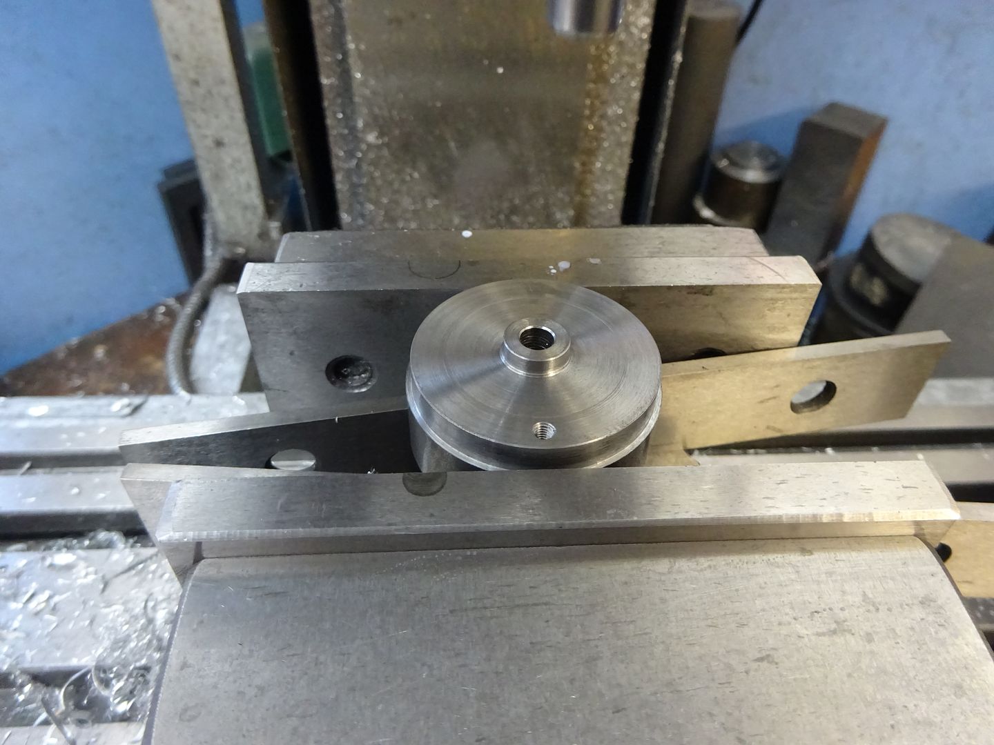
While held like this the Hole for the chimney can be drilled 9mm and then tapped M10x1, if you don't have fine pitch metric taps then 3/8" ME threads would do.
The base can now be held upside down in the vice with the flat edge against the fixed jaw, clocked central to the spindle and the four M3 clearance holes drilled, I tend to use 3.0mm drills for this as the socket head CSK screws tend to come in at about 2.8mm OD. I won't keep mentioning it but ease the edges of all holes either with a CSK bit or a lathe tool ground at 45degrees, you will often see these tools in the photos as it it the last op before taking the pic.

To mill the exhaust passage I dusted off the swivel base for my vice which was the first time I have used it in the 10yrs since I bought it, set the vice to 45degrees and then with an 8mm cutter cut the slot 3mm deep . If you don't have a swivel vice base then the base can be clamped directly to the mill table and the angle is not critical.

That's the first part out of the way
If anyone spots any errors on the drawings please let me know and I will update them, also feel free to ask any questions.
Edited By JasonB on 13/06/2017 20:06:52
14 June 2017 at 20:01 #302562 JasonBModerator@jasonb
Sub Base
Start by cutting a piece of 6mm aluminium a little larger than the 110mm required, locate the middle and dot punch. Mark out a 110mm circle with a pair of dividers, roughly mark 45degree lines and saw off the corners.

Clamp the plate to the mill table with some packing underneath then proceed to drill the four M3 clearance holes and the four 4.0mm holes which will be used to mount the engine to a wooden display base. Then with an 8.0mm dia milling cutter counterbore the 4.0mm holes 3mm deep and also cut a flat bottomed hole 2.0mm deep in the middle of the plate to locate the valve spring into. If you have a larger spring then make the hole to suit. Once removed from the mill table the underside can have the M3 clearance holes countersunk so your screw heads sit just below the surface.

Screw a piece of ply or MDF to the lathe faceplate of if you have a large enough 4jaw then the board can be held in that, use the tailstock centre in the dot punch mark to hold the plate to the board and then screw it on through the 4.0mm holes and turn the outside down to 110mm diamater.

Blue the plate in a couple of places and then offer up the base using a couple of screws in the M3 holes to line things up and scribe on its diameter.

Swing the topslide right round and set to about 4degrees then taper the edge of the plate until the cut runs out where the scribe marks are.

The last turning job is to add the decorative moulding to the edge which can be done by grinding up a small HSS form tool.

Finally back to the mill, pop two drill bits into the 4.0mm holes and locate them against one of the tee slots then locate the middle of the plate. Using the 8.0mm cutter again cut the other half of the exhaust passage 3.0mm deep

And a quick picture of the two parts together, I will give details of the spring later.

J
15 June 2017 at 07:03 #302601Raymond Sanderson 2
Participant@raymondsanderson2Following with interest
15 June 2017 at 10:55 #302643 VicParticipant@vic
Good on you for attempting this, I look forward to seeing it run. I have to say though that of all the vacuum engines I've seen this is just about the least attractive and difficult to build. I'm very much a fan of Jan Ridders work. His engines are very nicely designed and the plans are the best I've ever seen.
15 June 2017 at 11:05 #302646SillyOldDuffer
Moderator@sillyolddufferAny chance of a rough Bill of Materials Jason? I like to start a project by obtaining the raw materials first. It's to avoid disappointment when the builder suddenly says in Part 15 'I got the bar of depleted Unobtainium from a friendly Storeman in 1958…'. Not that you would ever do such a thing!
Thanks,
Dave
15 June 2017 at 12:47 #302665 JasonBModerator@jasonb
Vic, you obviously missed the video of the engine running that I posted the other day so here it is again.
As they say Beauty is in the eye of the beholder. I mentioned in the intro that I was attempting to replicate a specific engine that was originally made with castings so there will always be more work involved than if you were making a freelance barstock engine where you are able to do what you like.
I did not find anything too difficult about building it but that does obviously depend on the abilities of the individual and made it in two weeks of weekends and the odd evening. I would say it is easier than the Jowitt which I did a similar build thread for and quite a few of those have been made and are sucessfully running.
My plans can be used as a guide and built as anyone wants, if they feel one of the machining processes is difficult or not to their liking then it can be left off or adapted to suit so long as the basic workings of the design are retained. For example the base and sub-base would work just as well like this, not to my own tastes but may be to others but certainly less work involved.
Maybe I should repeat what I said at the start of the Jowitt build:
"Some of the parts could be simplified if you want to have a go but don't feel confident of things like shaping the cylinder or the angled cuts to the base and I will point these out as I go along. There are also other ways that most parts could be made, I have used what I have but feel free to ask if you don't have some of the equipment that I show"
J
Edited By JasonB on 15/06/2017 12:50:49
18 June 2017 at 14:43 #303060 JasonBModerator@jasonb
SoD Bill of materials to follow shortly.
Cylinder
This is probably the most involved part of the engine but if you take it one stage at a time it should not present too many difficulties.
It is just possible to squeeze the cylinder out of a piece of 50mm dia cast iron bar, anyone in the States thinking of making this will have a little more to play with by using 2" stock.
Start by sawing off a piece a few millimeters longer than needed and then lightly face to clean up the ends. Blue the end of the bar and then lay it onto a flat surface and scribe a line at centre height, roll it 1/4 of a turn and mart a cross line 3.5mm below ctr height. Accurately punch where the two lines cross.

Set the punch mark to run true by holding the bar in the 4-jaw chuck.

Then spot drill followed by drilling out most of the material with several drills of increasing size until you get to about 18mm when the rest can be bored out.

I like to do the last couple of cuts with a HSS boring bar as I find that springs less but even so take a few passes at the final setting to let any spring work its way out and hopefully you will get a parallel bore. Aim for something like 23.90mm which will allow for honing and lapping but as the piston will be made to fit the bore the turned finish is what to aim for not the exact size.
Talking of sizes I did not use a micrometer once on this engine all measurement was with a digital calliper.

Take a finishing cut across the bar and then take another 0.5mm deep cut to leave the small raised area 28.5mm dia, this raised area will make it easier to lap the end of the cylinder later.

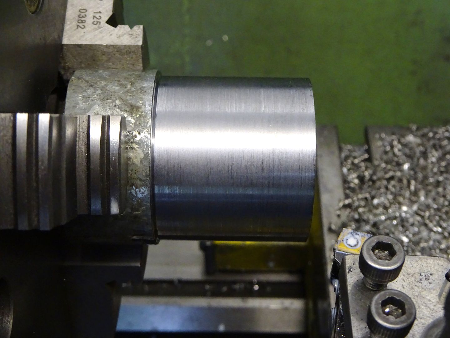
The work can now be reversed in the 4-jaw and the bore set to run true, make sure you can machine down to the top of the valve face which will probably mean the work is away from the chuck face. You may just be able to see that I have a piece of 1" material between chuck and work so it can't get pushed back by teh tailstock. NOTE this must be prevented from flying out for which I have used hot melt glue. Bring up the tailstock ctr for support and rough out to about 43mm dia.

Then with a tool that can get into a corner turn to 42mm finished dia and to leave 16mm for the port area.

Now form the spigot on the top of the cylinder to leave the 42mm dia section 50mm long.

Continued in next post.
Edited By JasonB on 18/06/2017 14:53:43
18 June 2017 at 14:52 #303062 JasonBModerator@jasonb
Next put your parting tool in the toolpost, set the front edge to touch the work and zero the cross slide dial. Then with the topslide touch the edge of the tool against the end of the cylinder, retract and move half the width of the cutter towards the headstocjk and then zero the topslide handwheel. This will make it easy to set the spacing of the fins as they are all dimentioned to their ctr from the top of the cylinder OD.
First make a central cut on each 5.5mm deep.

Then increase the width of the slots to 4mm by taking a equal cut off each side of the first grooves.

Then swing the topslide around to 5degrees and cut the taper down one side of each fin. Swing to 5deg the other side of zero and make a similar set of cuts down the opposite sides.


Grind up a 4mm square HSS tool bit to a half round profile and then round out the bottoms of the grooves, a slow speed will be needed to avoid chatter.

Then with a file the external corners can all be rounded over whith the lathe running.

Remove the tailstock and trim the spigot back to its final 5.0mm length.

With the largest part of the lower cylinder uppermost mill it back flush with the edge of the fins or just a fraction proud. Use a nice sharp cutter as we want a good finish here to save excessive lapping later on.

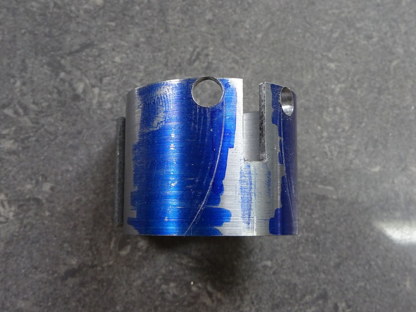
Centre up the port face and drill two 4.0mm holes 10mm each side of ctr into the bore, then another four holes will remove most of the material from the inlet passage. Finish up by cleaning out the slot with a 4.0mm milling cutter.

The cylinder can then be held bottom up on the rotary table and the two sides of the port machined as was done to the base.

Then again like the base round the rest to 42mm dia

Then add the four holes but this time thay are tapped M3.

Finally for now the five M2.5 hole scan be drilled and tapped in the top but make sure you drill them in the right place unlike me :-[ the one above the port face should be left out.

J
18 June 2017 at 17:20 #303072 JasonBModerator@jasonb
Bill of Materials to download
21 June 2017 at 18:35 #303593 JasonBModerator@jasonb
Bearing Support
I mentioned at the start that there were two pieces that are silver soldered fabrications, this is one of them and it is the one that if you are not able to silver soilder too well could probably be done by machining the vertical part into a "+" section and then tap this top and bottom for a couple of M2 CSK fixings each end. Though it would also be a good thing to get the hang of silver soldering on as there is not much material in it and if the worse came to the worse it could be melted apart, cleaned up and another go at soldering attempted.
I have shown the finished sizes on the drawing but strongly suggest that the top piece is made of something thicker than 3mm material and also left ovesize in the other two directions. It is unlikely that you could solder it all in exactly the right position but by leaving the top oversize it can me treated like a casting and machined exactly right once soldered.
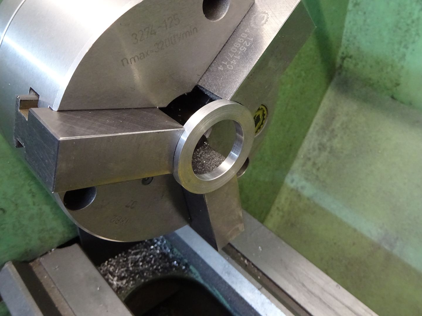
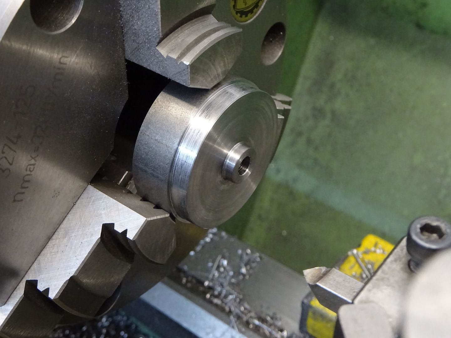
So make a start on the lower ring. Chuck a piece of 45 or 50mm dia bar, turn down a short length to 42mm dia, face the end and then drill and bore out to a nice snug fit on the 28mm spigot left on teh top of the cylinder. Saw or part this off and then face back to the finished 5mm thickness

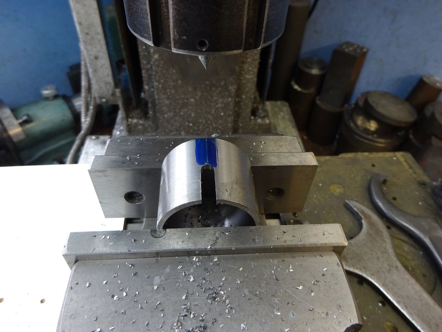
For the curved part of the upright I used a short length of scaffold pole skimmed inside and out to clean it up and then faced both ends to bring it to 32mm long. It could be cut from solid or even bent up from some 3mm flat, the exact curve is not really that critical.

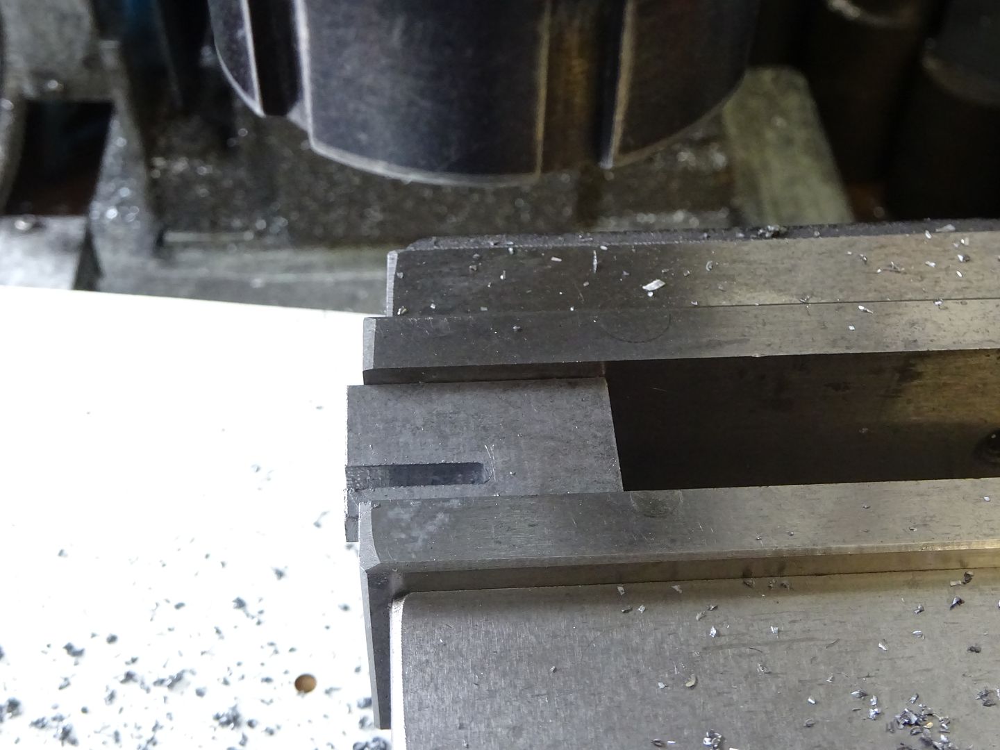
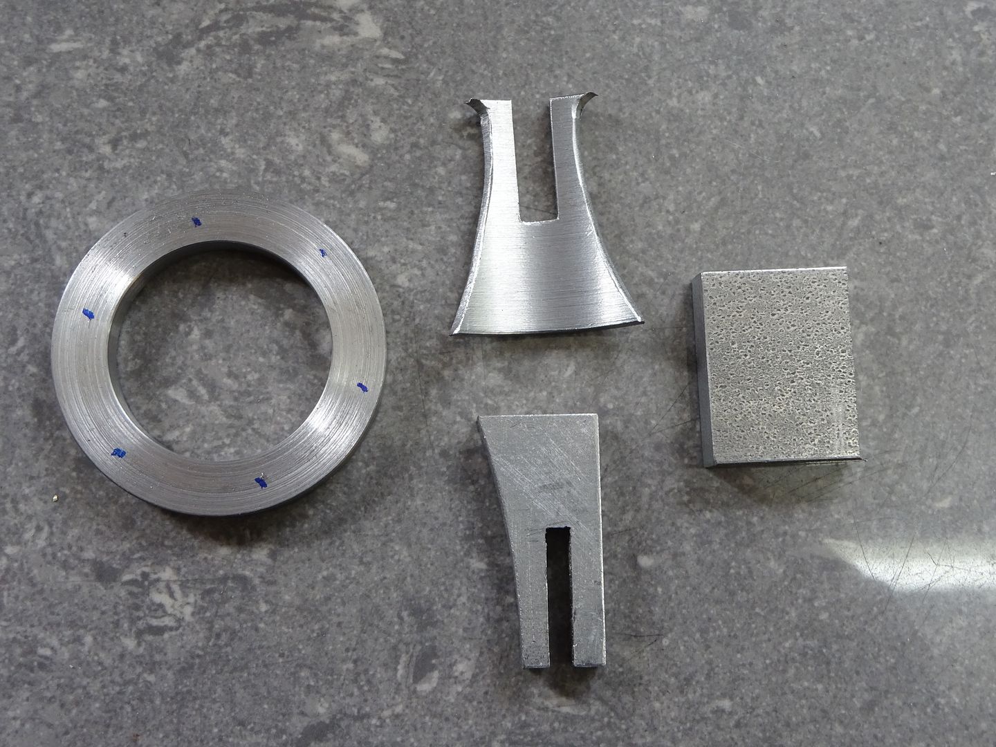
The cross shape is made with a halving joint so mill a 5mm slot half way up.

Then mark out a pleasing shape. I drilled 5mm at the top to leave a nice fillet shape and then drew the two larger curves by scribing around a roll of masking tape. Saw and file to your chosen design.

The other part of the cross is cut from a bit of 5mm flat plate and has the other half of the having joint milled in it a 3mm wide. Finally cut and file to shape. I would suggest the face that the valve rod guide screws to is also left overside at this stage.

Another bit of the 5mm stock forms the top plate, these are the 4 parts prior to soldering.

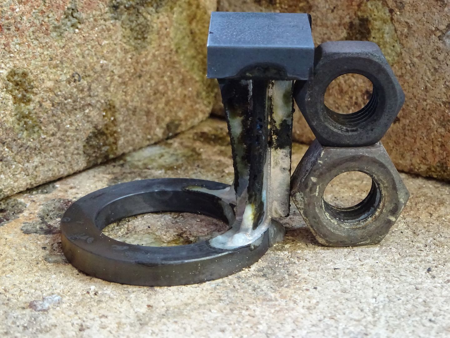
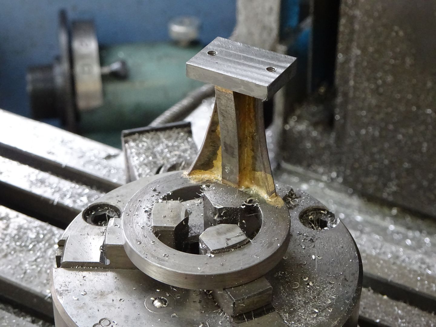
Give them a good coat of HT5 or Tenacity5 flux and place on the hearth, a couple of bits of scrap metal can be used to help steady things. Put a bend in your solder rod before starting to heat as it makes it easier to apply the first bit of solder under the top plate then chase the heat down with the flame watching the solder flow as you go adding more as needed.

Once cooled give the part a soak in your chosen pickle I tend to use brick cleaner now as it shifts all the black scale from soldering steel as well as the HT5 flux.
The part can now be held on the mill either using a chuck or clamped to the table. If holding in a small chuck as I have shown add a clamp or two to hold it down because the leverage from milling the top can pull it about a bit and result in a chip to a nice new milling cutter
 With it held in place locate the centre of the hole and from there the 4 sides of the top can be machined to the drawing dimentions and the two M2.5 holes drilled & tapped. Then mill the top down until the 40mm height is reached.
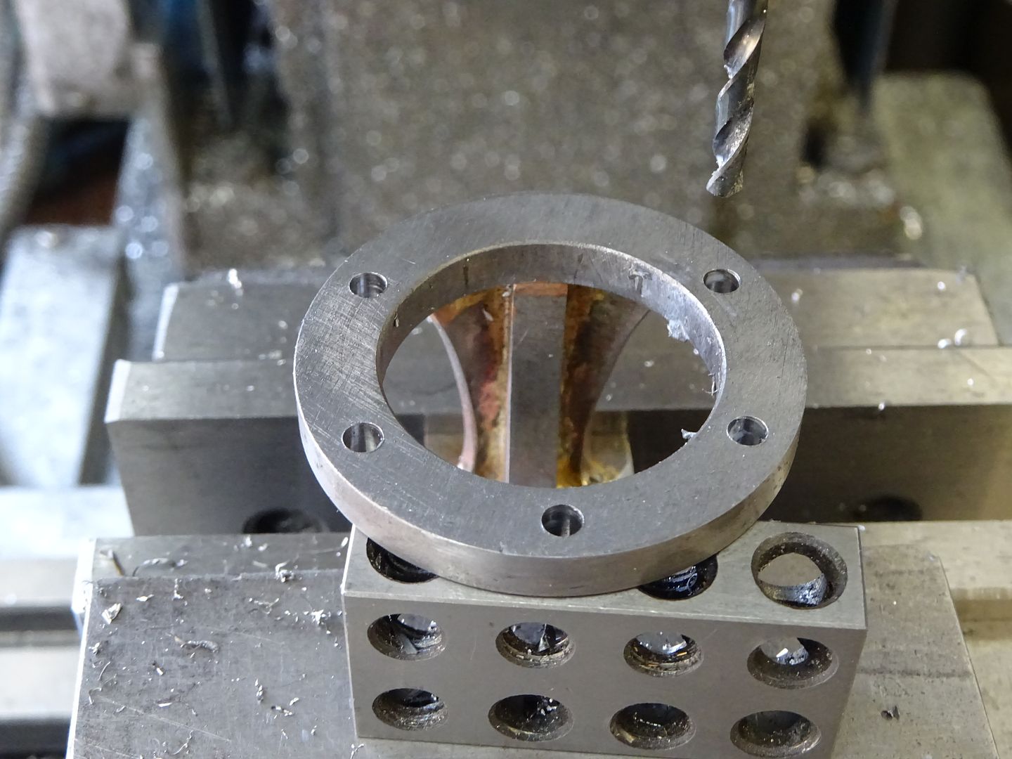
Now with the bracket upside down in the mill vice locate centre and drill the five M3 clearance holes on as 35mm PCD, support the overhanging edge so it does not move under pressure from the drill.

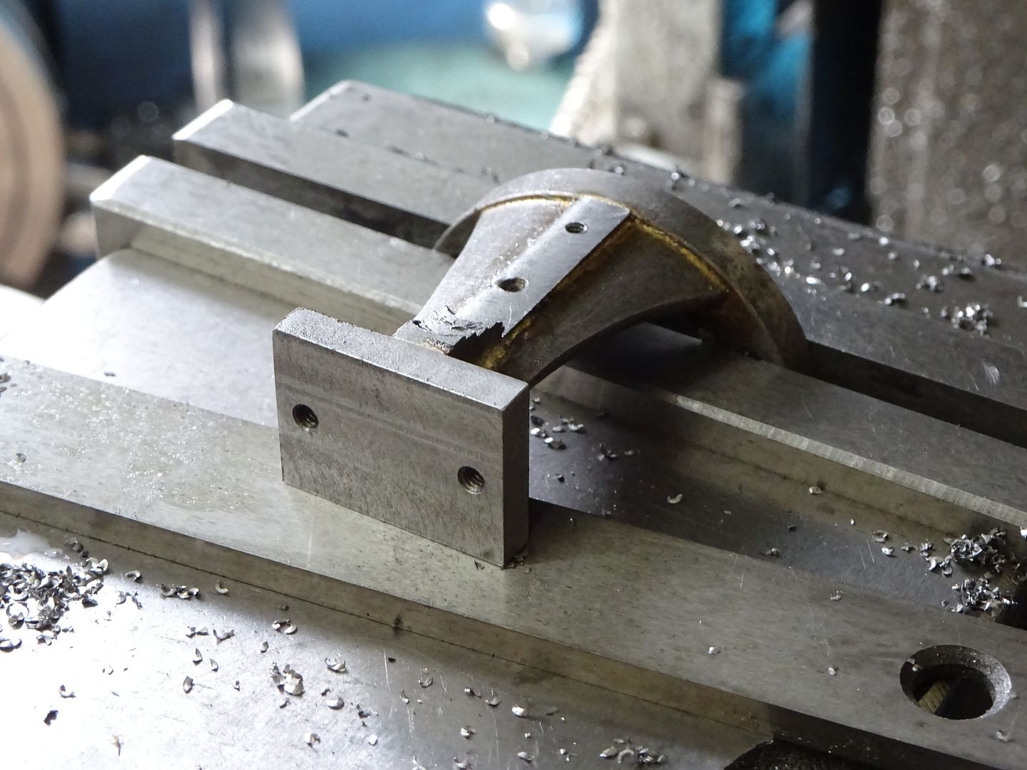
Holding by the round ring and with the long side of the top on the flat of the vice the surface for the valve rod guide can be milled back until the cutter just skims the edge of the ring which will put the surface 21mm from ctr. Don't mill right upto the top plate but feather out the cuts and afterwards file to a pleasing radius. The two M2 holes can also be drilled and tapped at this time to complete another part.

J
21 June 2017 at 19:59 #303601SillyOldDuffer
Moderator@sillyoldduffer25 June 2017 at 18:47 #304159 JasonBModerator@jasonb
Piston and Associated Parts
Before starting on the piston it is best to hone the cylinder, this can be done quite easily with one of the cheap brake cylinder hones. I run these in the bench drill at about 750rpm and just move the cylinder gently up and down making sure not to let the stones stick out too far and risk a bell mouth end, a little paraffin will help stop the stones clogging.
The piston will come out of a length of 25mm cast iron bar, face it off then turn the outside until it just enters the cylinder bore. Check against both ends of the bore, if one is smaller then use the hone some more to remove any taper. Once you have a push fit into the cylinder stop working on the outside and bore the inside followed by drilling and tapping for the M3 thread.

Saw or part off the piston and then face off to 20.5mm finished length being careful not to distort or crush the now hollow piston. Face off and tap a bit of say 12mm bar to take an M3 screw and this can be used as a mandrel to hold the piston while it is lapped into the bore. This is easily done at a slow speed with a small amount of 1000g silicon carbide powder and a liberal amount of oil. Just work the cylinder onto the piston from the top until it is a close but friction free fit. Clean off all traces of SiC powder.

The lug for the gudgeon pin can first have the end reduced down to 3mm and then be threaded M3

Then mill it to a square section if you have not started with square bar. This can then be cut off the main bar and milled to length and a 3mm slot cut into it.

Followed by the drilled and reamed cross hole after which the end can be rounded off by filing or machining.

The gudgeon pin is a simple turning job. Onec done blue the end, put it in teh hole and mark off the position of the split pin hole. Then drill for a 0.8mm (3/32"
 split pin.
This pic shows the finished parts along with the conrod which is still to be descibed.

J
3 July 2017 at 19:44 #305399 JasonBModerator@jasonb
Crankshaft Parts
I made a start with the crank web and to make it easier to hold actually machined it on one end of a short length of 40mm dia steel bar and the cam on the other end.
Start by facing the end of your stock, then using a tool with a small radius on the corner turn the 3mm long spigot and also the 38mm OD. Followed by drilling and reaming the central 5.0mm hole.

Transfer to the mill, locate centre and then use the handwheel dial or DRO to move 16mm and then drill and tap M3.

Saw or part off and then holding by the spigot clean up the other side but leave the web about 0.5mm over thickness at this stage. Mark out the two straight edges, saw off the waste and then mill back to the lines.

A bit of simple file work will round off the edges.

The crank shaft can be made from precision ground mild steel (PGMS) or silver steel, stainless would also be OK if it is a good fit in your bearings. Face it off either end but leave it 1.0mm longer and then turn the spigot also 1.0mm over length. The crank web can be used as a gauge to get the spigot a firm push fit into the hole. Once done clean up both parts and loctite them together.

Once the Loctite has had a good time to set the crank can go back into the lathe to have the web faced down to the final 3mm thickness. Doing it this way will ensure the face of teh web is at right angles to teh shaft even if it went on a bit crooked when loctited.

The crank pin is fairly straight forward turning, put a small undercut at the base of the thread to ensure it screws right into the web and the shoulder makes contact. Saw or part off then clean up to leave the lip 1.0mm thick and add a small chamfer.
J
13 July 2017 at 19:25 #307009 JasonBModerator@jasonb
Cam Disc
I machined this on the other end of the bit of 40mm dia steel that the crank came out of.
Start by facing the end and then turn the 12mm dia x 6mm long spigot followed by drilling and reaming 6.0mm

The cam can be formed in a number of ways: milling, turning in the 4-jaw or even filing to the template included on the drawing. I opted to mill it using the rotary table as follows
– centre the rotary table under the spindle and zero the dials or DRO, lock y axis
– hold work in chuck , put a 6mm rod in the collet chuck and bring down into the hole
– move table 11mm in the x plane allowing the chuck to slide along the rotary table
– Bolt chuck to R/T
– Fit a cutter into the collet chuck and work your way in from the edge rotating the work on the table until the x axis is 25mm plus half your cutter dia.
Saw off from the rest of the bar and then hold by the spigot in the 3-jaw, face back to 3.5mm thick and then take a further 0.5mm cut but stop to leave the 8mm raised area in the middle which will make sure the cam only contacts the bearing inner race.

You could mill the two 10mm radius corners that blend the arc into the main diameter but I just opted to file it to shape.
Final job is to drill and tap for a M3 grub screw.

J
18 July 2017 at 19:16 #307784 JasonBModerator@jasonb
Bearing Block
Start by milling up a block of aluminium to the overall 16x22x17mm. Then hold in the mill vice with the top facing upwards and locate it centrally below the spindle followed by drilling the two M2.5 clearance holes.

Change to a 6mm dia cutter, touch off on the top of the block and then lower so you are taking a 3mm high cut, cut in 4.29mm from each side and while at that height bring the cutter in from each side to form the counterbore centrally over the stud holes.

Now holding the block on it side drill and then bore for the bearings aiming for a light press fit, if you over do it then a high temperature Loctite such as 648 can be used to retain the bearings. I opted to use number 686 unshielded bearings which are 6x13x3.5 from ARCEurotrade but 12mm OD ones would work just as well. As the flame can lick around the bearings avoid ones with rubber seals though if you have some to hand the seal can be flicked out with a pin or small jewlers screwdriver.

The last job is to round over the top, I did it by holding the work on a mandrel and then taking cuts at 5degree intervals on the spin indexer and then finished with a file. Could also be done on a rotary table or just by filing.

You can now fit the bearings, slip in the crankshaft and check all turns over nice and smoothly.

Included on the drawing are the 4 simple turned "washers" that fit into the counterbored holes in the sub base, once bonded in with JBWeld or similar they will look like cast. bosses. Turn and drill sufficient material for the 4 parts and an allowance for parting cuts and then part them off and deburr.

J
30 July 2017 at 19:25 #309525 JasonBModerator@jasonb
Chimney
The main chimney is a simple job from 10mm OD aluminium tube, thread one end M10x1.0 for a length of 22mm. Face to length and form the 9mm dia spigot on the other end. I used slightly larger OD tube so had to machine it down to overall diameter.

The base is just some 12mm stock drilled to 9.0mm and tapped M10x1.0 with the upper edge rounded off.
The top ring can be turned on the end of some bar and if you put a parting cut part way through so the bead can be easily shaped the drill will part off the work as it brakes through.

The parts can be assembled with a drop of Loctite 648 to hold the ring in place, make sure you have no more than 2mm of thread sticking out the bottom otherwise the exhaust passage in the base will be restricted.

And a quick test fit to round off this installment.

J
30 July 2017 at 21:39 #309542Ian Skeldon 2
Participant@ianskeldon2Nice one JasonB, I love the video of it running, nicely made flame gulper as well.
24 September 2017 at 20:41 #318478 JasonBModerator@jasonb
Conrod
This could be turned from a length of 10mm aluminium 6082 but I had a lot of 1/2" (12.7mm) so used that.
Cut off a piece about 20mm longer than needed, face each end and put in a small size 0 ctr drill hole, reduce one end to 8mm dia and the other to 10mm if using larger stock.

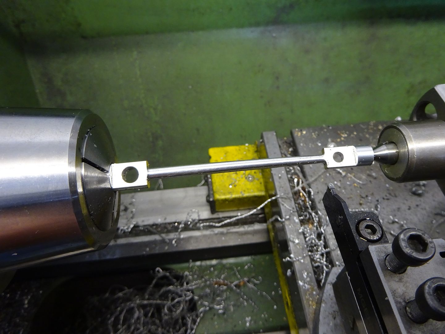
Now holding the rod in a mill vice the two holes can be drilled and reamed and the ends flattened off.

Back to the lathe hold the 10mm end in a collet or 3-jaw and offset the tailstock to form the taper, I used a small live ctr in a boring head to get the offset rather than disturb the setting. You could also set the topslide to an angle if prefered. Do the final cut swith either a small HSS tool with a rounded end or an insert tool like I used in the photo to give the fillet where the round rod joins the flat ends. Do take it easy as the rod is getting quite thin at this stage but will be nice and light.

The two bearings are simple turning jobs from a bit of bronze bar with reamed holes. I find the mill vice is quite good for pressing them in, use a spacer on the big end so the bearing can protrude evenly both sides. If your fit is a bit loose then high temp Loctite such as 648 should hold the bearings in place.

This is the finished rod together with the Gudgeon pin block and piston described earlier

That's another bit off the list, hopefully you won't have to wait so long for the next installment
J
24 September 2017 at 20:57 #318482SillyOldDuffer
Moderator@sillyolddufferPosted by JasonB on 24/09/2017 20:41:53:Conrod
…
That's another bit off the list, hopefully you won't have to wait so long for the next installment
J
Not a problem Jason – I'm still collecting metal!
As I'm a slow worker and easily distracted it will be a few weeks before I'm ready for this one. But I'm looking forward to it.
Dave
27 October 2017 at 20:19 #323959 JasonBModerator@jasonb
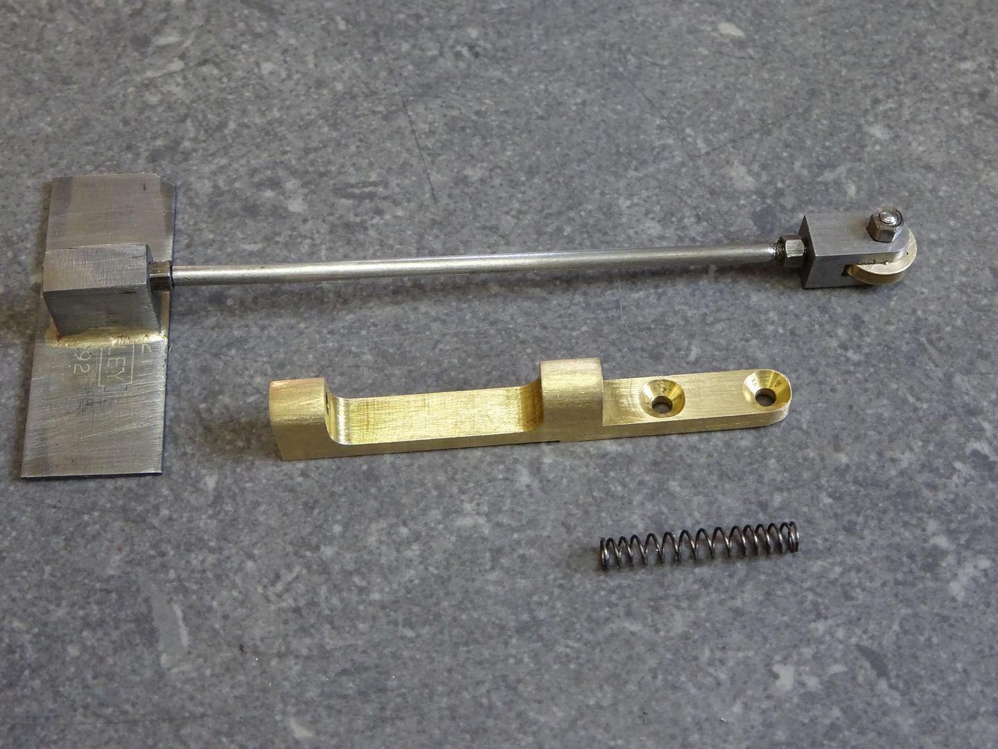
Shutter parts
Shutter Rod Guide
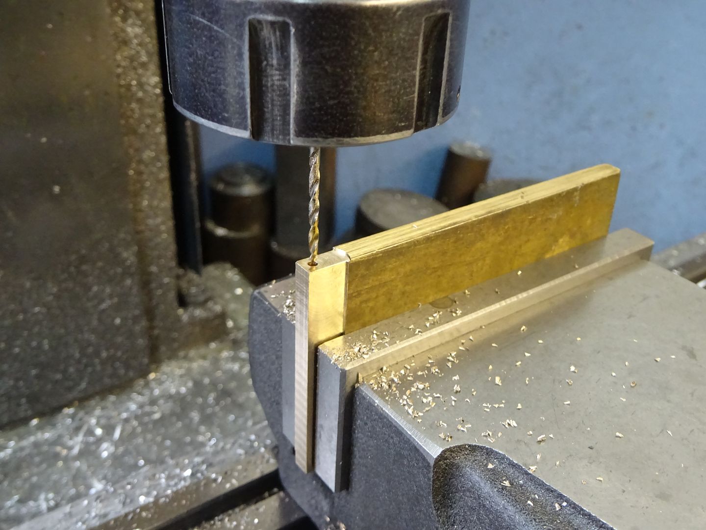
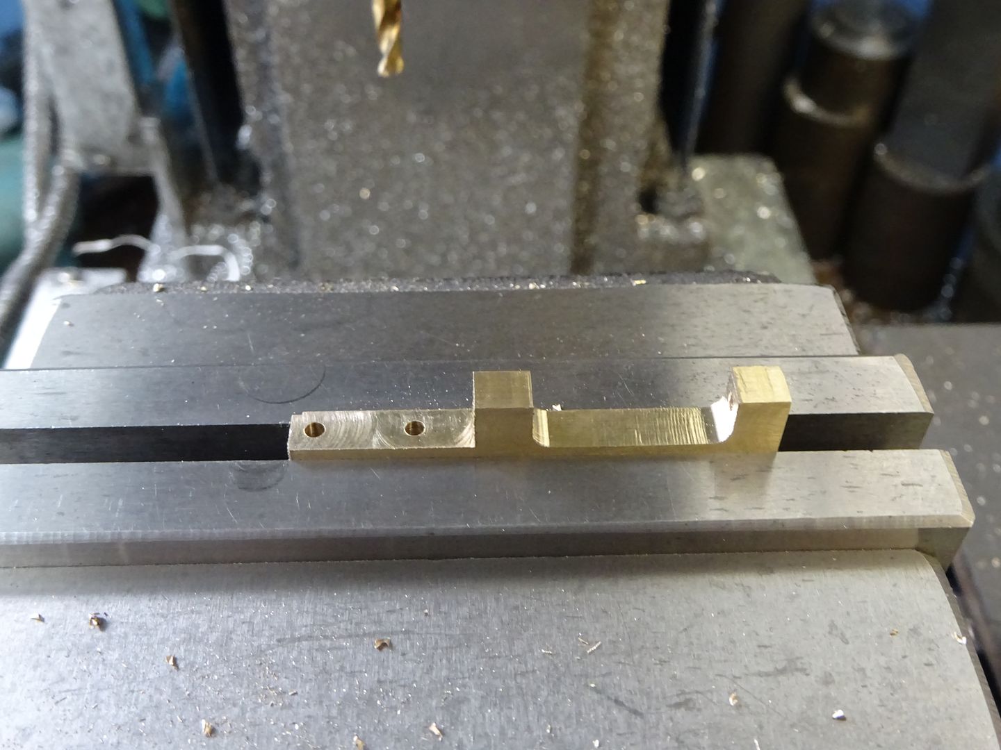
I did not have any 5mm thick brass so thinned down the end of a piece of 1/4" material and then drilled the 2.0mm hole at least 31mm deep.

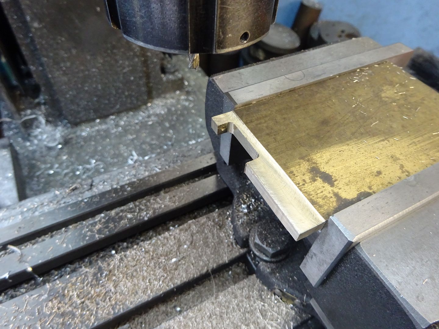
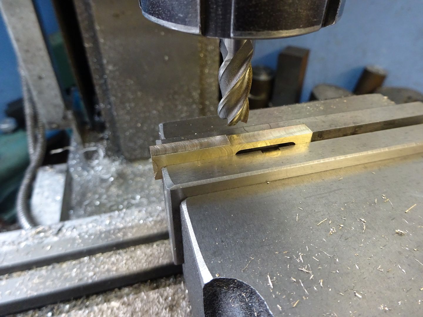
With the work now on it's side the recess was milled out with a 6.0mm cutter to give the required 3.0mm radius to the internal corners.

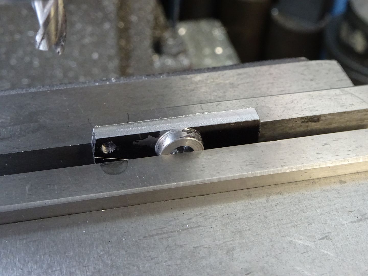
After cutting off from the parent bar the back face is milled to finished size and then the 1.0mm step cut from the lower end.

Turning the part the other way up the larger recess can be milled out, the two 2.0mm holes drilled and then countersunk then finish off by filing the 2.5mm radius around the upper screw hole.

Shutter
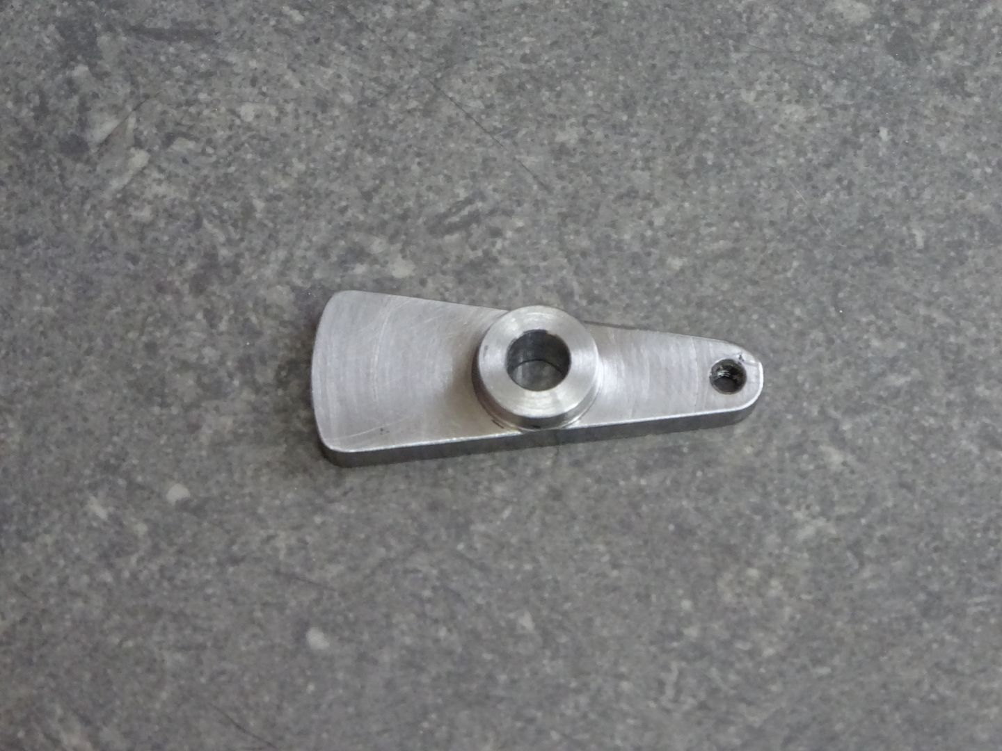
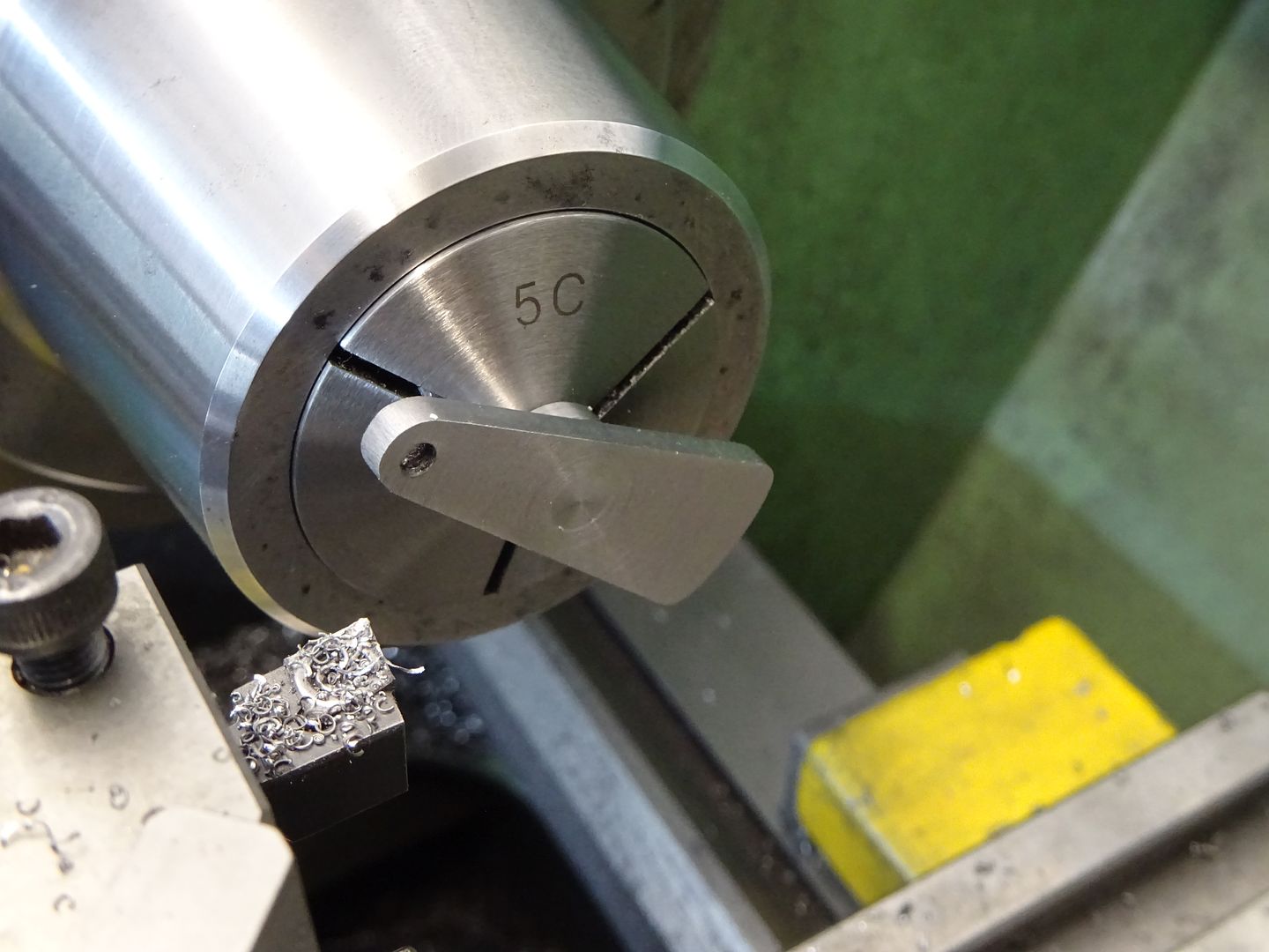
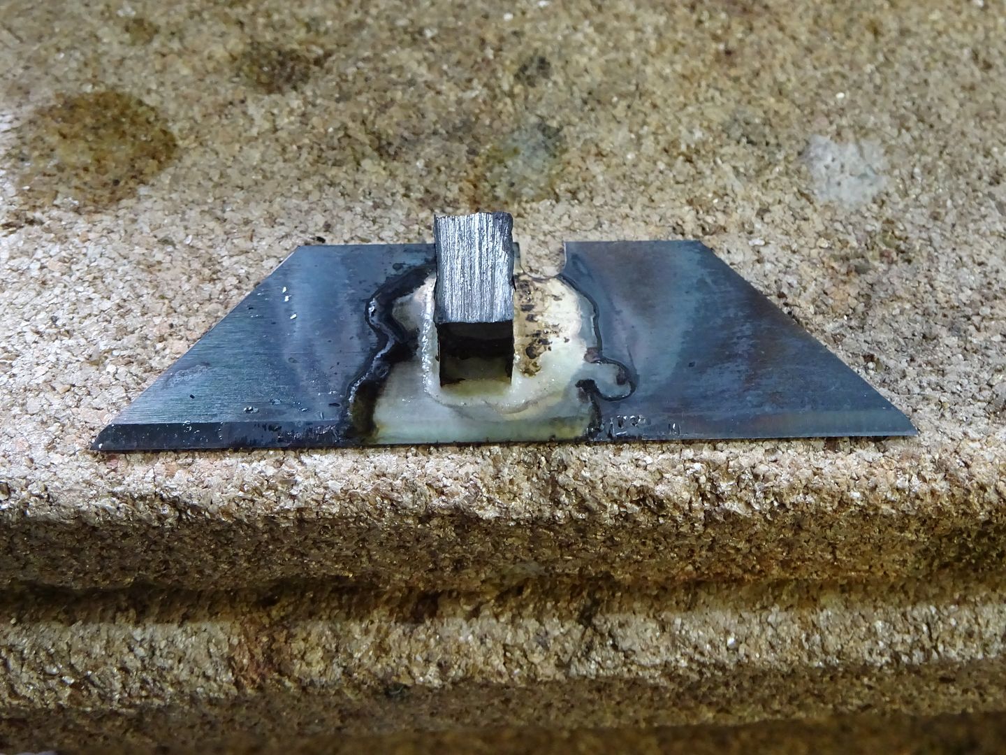
This starts life as a Stanley knife blade or "utility" knife as I think our American members call them. It is best to shape the knife blade after the steel block has been soldered on just in case it moves about during silver soldering. Also worth leaving te block a bit long to start with so just make teh 5×8 dims to finished size then solder.

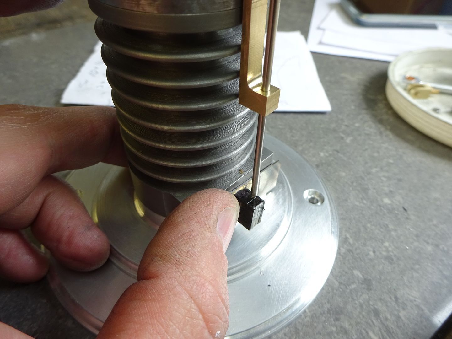
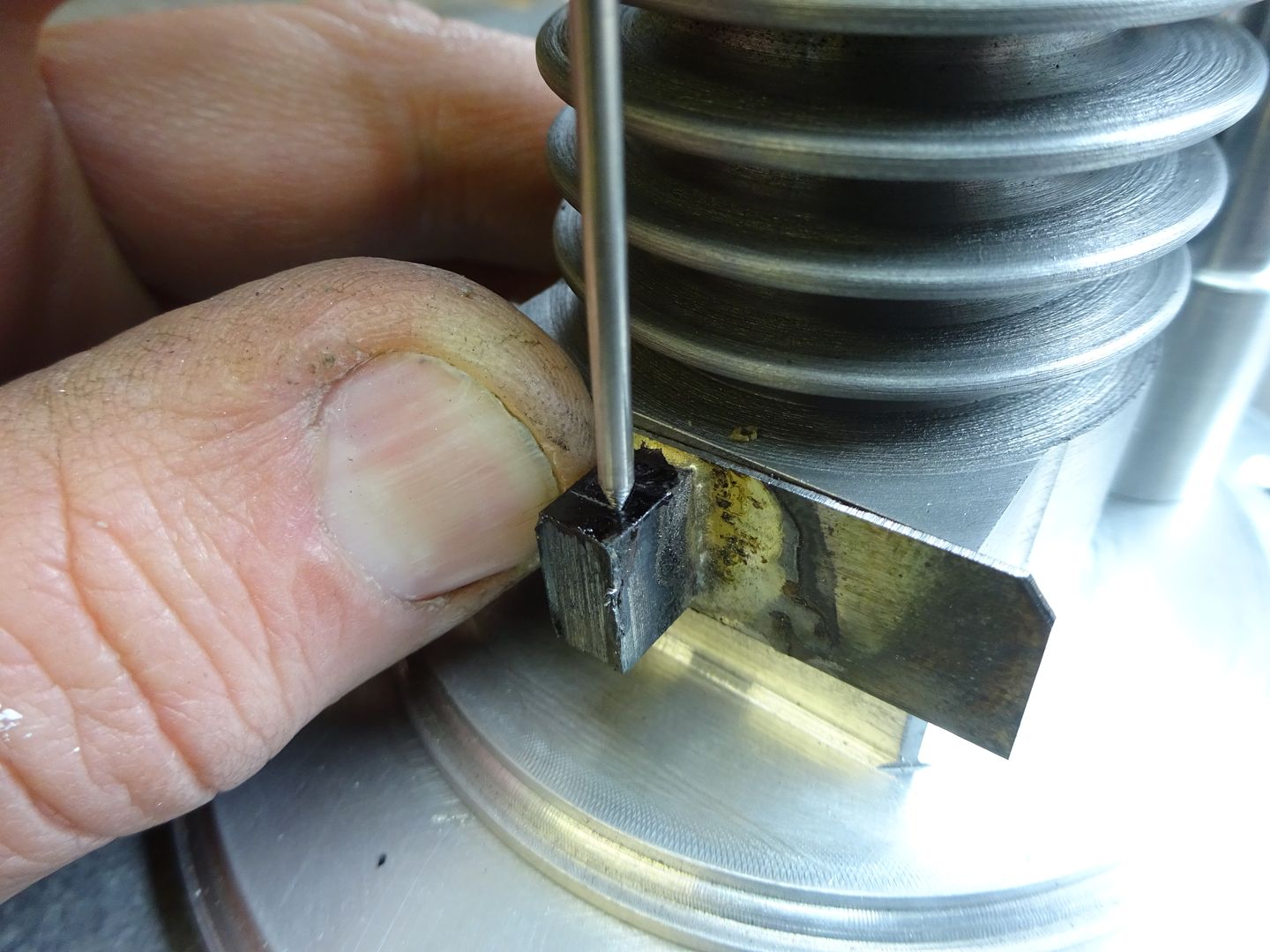
The blade can then be roughly trimmed to size making sure the edges are true to the edges of the block. With the rod guide screwed into place machine a point onto some 2.0mm rod and pass that through the guide and use the rod as a scriber to mark the position of the M2 hole.


The hole can now be drilled and then tapped M2 and the block rounded over. I would suggest leaving the final shaping of the shutter until it is mounted on it's rod.
Shutter Rod
This is quite a simple job so no photos, face the rod to length and cut the M2 thread on each end to the lengths required.
This shot shows the finished part , the fork and cam follower roller will be covered next time.

J
1 January 2018 at 04:54 #334705Raymond Sanderson 2
Participant@raymondsanderson2Thanks Jason been a while since pocking my head over the fence but I have been peering through if you get my drift.
A mate and myself really interested in making this, how much further is there to go ??
Ray
1 January 2018 at 07:05 #334709 JasonBModerator@jasonb
Very Little, I'll try and get it up in the next few days
1 January 2018 at 17:34 #334800SillyOldDuffer
Moderator@sillyolddufferI've got this one firmly on my to do list. All I need to do is work faster on my existing backlog. Much faster…
Dave
-
AuthorPosts
- Please log in to reply to this topic. Registering is free and easy using the links on the menu at the top of this page.
Latest Replies
Home › Forums › Work In Progress and completed items › Topics
-
- Topic
- Voices
- Posts
- Last Post
-
-
Source of 8mm Dia flexible stainless steel tubing
Started by:
Greensands in: Materials
- 6
- 6
-
17 April 2025 at 02:57
Pete
-
Acceptable feed screw backlash
Started by:
david newman 9 in: Hints And Tips for model engineers
- 10
- 11
-
17 April 2025 at 02:31
Pete
-
Not a dial indicator!
Started by:
 Sonic Escape
in: The Tea Room
- 4
- 4
-
17 April 2025 at 00:19
 Nicholas Farr
-
Metric Thread Cutting Without Conversion Wheel
Started by:
Nigel Graham 2 in: Hints And Tips for model engineers
- 5
- 7
-
16 April 2025 at 23:18
 halfnut
-
Colchester Chipmaster tailstock shimming
Started by:
Peter_H in: Manual machine tools
- 3
- 3
-
16 April 2025 at 23:15
 halfnut
-
What Did You Do Today 2025
1
2
3
4
Started by:
 JasonB
in: The Tea Room
- 25
- 82
-
16 April 2025 at 22:50
Nigel Graham 2
-
ME No155 Vol10 pg 359 of 1904
Started by:
 JasonB
in: Stationary engines
- 3
- 4
-
16 April 2025 at 22:20
Nigel Graham 2
-
Stuart Twin Victoria (Princess Royal) Mill Engine
1
2
…
48
49
Started by:
Dr_GMJN in: Work In Progress and completed items
- 32
- 1,218
-
16 April 2025 at 22:14
 Michael Gilligan
-
Hitachi SJ300 VFD problem
Started by:
Clive Steer in: Electronics in the Workshop
- 1
- 1
-
16 April 2025 at 22:02
Clive Steer
-
Index cutter for flycutter
Started by:
petro1head in: General Questions
- 3
- 4
-
16 April 2025 at 18:45
 Vic
Vic
-
Myford Super 7 questions
1
2
Started by:
davp1971 in: Help and Assistance! (Offered or Wanted)
- 16
- 29
-
16 April 2025 at 17:48
davp1971
-
High tensile M6 bolts
Started by:
nevillet in: Materials
- 12
- 20
-
16 April 2025 at 17:20
old mart
-
New ELS-fitted Lathes from Amadeal
Started by:
 Neil Wyatt
in: CNC machines, Home builds, Conversions, ELS, automation, software, etc tools
- 12
- 23
-
16 April 2025 at 17:15
David Senior
-
1800 Mechanical Movements …
Started by:
 Michael Gilligan
in: Books
- 7
- 8
-
16 April 2025 at 15:24
 Harry Wilkes
-
Unknown Beam Engine
Started by:
Jeff Swinburn in: Stationary engines
- 2
- 3
-
16 April 2025 at 14:31
Jeff Swinburn
-
Greenwood Tools Information Sheet
Started by:
ron61630 in: Help and Assistance! (Offered or Wanted)
- 5
- 5
-
16 April 2025 at 12:43
Trevor Drabble 1
-
Shop Tips
Started by:
 Vic
in: The Tea Room
- 3
- 5
-
16 April 2025 at 12:31
 Michael Gilligan
-
Abrasive tape/paper recommendations please
Started by:
Richard Evans 2 in: General Questions
- 7
- 11
-
16 April 2025 at 09:12
Richard Evans 2
-
Air source heat pumps
1
2
Started by:
Plasma in: The Tea Room
- 22
- 47
-
16 April 2025 at 08:55
Plasma
-
Pipe Unions, Fittings, Standard Dimensions, CAD
Started by:
 MEinThailand
in: CAD – Technical drawing & design
- 8
- 14
-
16 April 2025 at 08:31
 MEinThailand
-
Half Scale 1/4HP A J Weed Engine
Started by:
 JasonB
in: Stationary engines
- 4
- 15
-
16 April 2025 at 06:46
Diogenes
-
Generator size for vfd controlled 3 phase 5.5 kw motor
1
2
Started by:
PutneyChap in: Electronics in the Workshop
- 10
- 32
-
15 April 2025 at 22:55
Stuart Smith 5
-
Building Bernard Tekippe’s Precision Regulator
Started by:
Chris Raynerd 2 in: Clocks and Scientific Instruments
- 8
- 17
-
15 April 2025 at 16:49
Chris Raynerd 2
-
Amadeal VM25L Uneven Motor Brush Wear
Started by:
Richard Kirkman 1 in: Help and Assistance! (Offered or Wanted)
- 6
- 11
-
15 April 2025 at 13:03
Richard Kirkman 1
-
1965 Colchester Chipmaster
Started by:
andyplant in: Introduce Yourself – New members start here!
- 4
- 7
-
15 April 2025 at 11:01
Emgee
-
Source of 8mm Dia flexible stainless steel tubing
-
Latest Issue
Newsletter Sign-up
Latest Replies
- Source of 8mm Dia flexible stainless steel tubing
- Acceptable feed screw backlash
- Not a dial indicator!
- Metric Thread Cutting Without Conversion Wheel
- Colchester Chipmaster tailstock shimming
- What Did You Do Today 2025
- ME No155 Vol10 pg 359 of 1904
- Stuart Twin Victoria (Princess Royal) Mill Engine
- Hitachi SJ300 VFD problem
- Index cutter for flycutter


