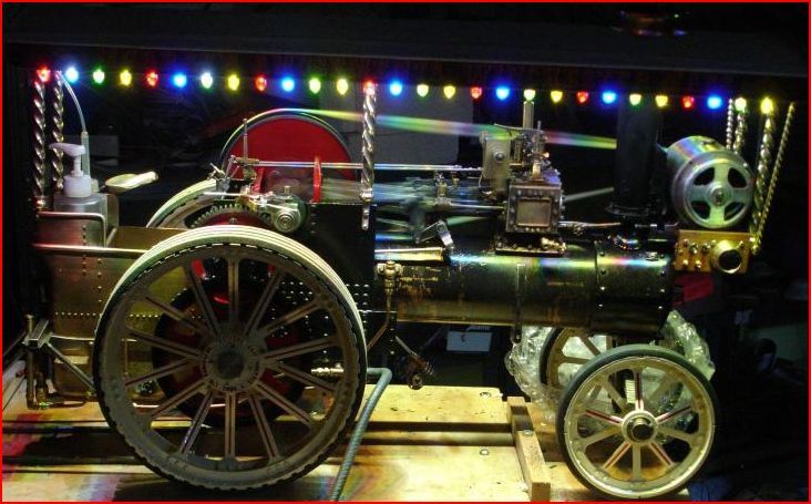
Showmans engine generator

Advert

Showmans engine generator

Home Forums Work In Progress and completed items Showmans engine generator

Viewing 25 posts - 1 through 25 (of 53 total)
  • Author
    Posts
  • #260012
    Scrumpy
    Participant
      @scrumpy

      i have been looking for some time to make a generator for a 2 in showman, I have tried various avenues with no luck but on looking at traction talk form a person from America has made the generator using a air craft motor as a generator along with a rectifier and led lights has anyone come across this before or has any information or advice as it looks to work

      Advert
      #31140
      Scrumpy
      Participant
        @scrumpy

        Advice

        #260032
        JasonB
        Moderator
          @jasonb

          I've seen that one in the flesh and it works very well and looks right on the small 2" Gold Medal Tractor.

          #260039
          Anonymous

            Clearly the system works well, although I'm not sure why he only used half wave rectification, and there are probably better regulators than the 2940 available. I assume that the LEDs are running in parallel?

            Andrew

            #260068
            John Olsen
            Participant
              @johnolsen79199

              I presume that what is meant is a model aircraft motor. The usual type has a permanent magnet rotor and a three phase stator arrangement. If the rotor is powered they will generate three phase power which may be rectified and used to charge a battery or power a load. This makes them quite similar to the permanent magnet alternators that used to be common on motorcycles.

              The characteristics of a permanent magnet machine like this is that the voltage will rise with speed. The bikes used to get around this by connecting the rectified output to a battery, and by winding the machine with two sets of coils. The battery limited the voltage that could be reached so that the alternator was actually delivering its maximum current. The two windings were then arranged so that one provided enough current for the normal load, and the other provided enough for the lighting load. This was all a bit approximate and these simple arrangements had a tendency to cook their batteries.

              In the late sixties and seventies, electronics started to provide better solutions. Lucas used a zener diode and others used various forms of shunt regulator. This is the way I would go if I wanted to use one of these on a traction engine. The alternator has to be turned fast enough to generate a bit more than the voltage required, and the output is rectified with a three phase rectifier. Either a battery or a large capacitor is used to smooth the output, and a shunt regulator (eg the Lucas Zener) is used to dump any excess current.

              The model aircraft motors are usually outrunners, eg the rotating armature with the magnets is on the outside. For generator use it might be more convenient to find an inrunner of the desired size. These have the armature inside, more like a conventional motor. Of course for traction engine use it might be desirable to hide the whole thing inside a scale looking casing anyway. The beauty of these motors for this purpose is that there are no brushes to wear out.

              John

              #260070
              Anonymous
                Posted by John Olsen on 08/10/2016 23:43:04:

                I presume that what is meant is a model aircraft motor.

                Correct, and in the original post on TT it is stated that the motor is an outrunner, and outputs three phase. That's why I thought it was odd that a half wave rectifier was used. It is also stated that the output voltage is proportional to speed. While I realise that a linear regulator is simple personally I'd use a switcher rather than throwing energy away. It'll probably be smaller than the heatsinks. I'd go for a buck or SEPIC converter, the latter coping with input voltages above and below the output voltage.

                There were no schematics or details in the original TT post, but the picture sure looks impressive with all the LEDs emitting.

                Andrew

                #260078
                John Olsen
                Participant
                  @johnolsen79199

                  There is a reason why the motorcycles mostly used a simple shunt regulator. The alternator has to be designed so that it will start charging at some reasonably low rpm. Say 1 quarter of maximum rpm. That means that it will be able to produce 4 times the voltage at maximum, and if a series type of regulator is used, it must cope with that on the input, as must the rectifier. At least one bike I tinkered with was capable of around 80 volts open circuit. In the days of selenium rectifiers it was important not to open circuit the connection to the battery since this could destroy the rectifier. With a shunt regulator and a bridge rectifier nothing sees anything more than the battery voltage. So long as it is connected to the battery then the voltage cannot rise higher, and the alternator will act as a constant current source.

                  OK, with a showmans engine running its lights, possibly with a working governor, the speed variations are not going to be so great, so a more sophisticated regulator could be used. It will have to be able to cope with variations in the input voltage, as will the rectifier and smoothing capacitor. All quite doable, especially in these days of supplies which will run OK off either 240V or 110 V without adjustment. But I would ask if the relative inefficiency of the regulator is going to matter, when the efficiency of the steam part of the cycle is not likely to exceed 2%. (Going by IMLEC results over the years.)

                  John

                  #260092
                  Martin Connelly
                  Participant
                    @martinconnelly55370

                    You may be able to use the generator from a hand crank radio or torch (flash light) as the basis for a generator. Fit it into a package of your own design to look the part.

                    Martin

                    #260103
                    JasonB
                    Moderator
                      @jasonb

                      2inch lighting.jpg

                      #260109
                      Michael Gilligan
                      Participant
                        @michaelgilligan61133

                        Looks very effective, Jason yes

                        Just a thought … is there anything wrong with the traditional bicycle dynamo for this application?

                        MichaelG.

                        #260113
                        peter ravenscroft
                        Participant
                          @peterravenscroft57700

                          there is one described in the construction articles for the Darjeeling loco based on a hand wound torch i have built on and it works ok

                          regards

                          peter

                          #260119
                          Anonymous
                            Posted by John Olsen on 09/10/2016 05:32:35:

                            OK, with a showmans engine running its lights, possibly with a working governor, the speed variations are not going to be so great, so a more sophisticated regulator could be used. It will have to be able to cope with variations in the input voltage, as will the rectifier and smoothing capacitor.

                            Surely that's the whole point of a switcher, it can cope with a wide input voltage range without the high dissipation at higher input voltages. As a result of the push for 42V automotive electronics there are switching ICs available that will run from 5V to >50V input. The need to run on a governor for a switcher is irrelevant, as is the efficiency, or otherwise, of the steam engine.

                            I've just re-read the original post on TT. At 250rpm the OP gets just enough voltage to run the 5V regulator. He is running the LEDs at 15mA, and I estimate there are about 60 LEDs, so around 0.9A. Given a 0.5V drop across the regulator, that's about 0.45W, quite manageable with one of the bigger IC packages. However, the OP states that at maximum speed the output is 15V, so now we have 9W of dissipation, which is going to need a heatsink. One of the original issues was finding a small enough generator to fit within the existing dummy generator casting set. So finding room for a heatsink might be a problem.

                            The one and only time I've seen a power Zener diode shunt regulator was back in the late 1980s on an Indy car, but of course that was sitting in a 200mph breeze, so heatsinking was not a problem.

                            Andrew

                            #260121
                            Scrumpy
                            Participant
                              @scrumpy

                              Hi All many thanks for all your help with this topic I agree the photo looks very impressive, last evening at a steam up I was offered two Outrunner motors the details are . Motor (1) Shina Emax bl2815. 920 Kv Outrunner brushless motor max current 30 amps . Number (2) Turnigy D3548/4 brushless 1100Kv max load 50 A Max power 910 w

                              Would either of these be of any good to me powering led bulbs at 20ma there would be 50 of them 3.5 forward voltage ? what ever that means and what rectified controls would be required these motors come free as the one that is lit up works out at 150 pounds and I need two could some one explain how to wire this up if either motor will do as I see three phase is involved any circuits or diagrams would be appreciated sorry for being so thick on this as I have had no dealings when it comes to this side of thinks

                              The Showmans engines I have would run at 200/250 rpm governed driving the generator, would I wire the bulbs in parallel or series and would it be advisable to have two separate circuits many thanks in anticipation .

                              I'm sure many people will be interested in this

                              #260129
                              Michael Gilligan
                              Participant
                                @michaelgilligan61133
                                Posted by Andrew Johnston on 09/10/2016 11:33:29:

                                The one and only time I've seen a power Zener diode shunt regulator was back in the late 1980s on an Indy car, but of course that was sitting in a 200mph breeze, so heatsinking was not a problem.

                                .

                                Andrew,

                                For info. … Here's the Triumph motorcycle one:

                                **LINK**

                                MichaelG.

                                #260130
                                Neil Wyatt
                                Moderator
                                  @neilwyatt

                                  If I was going to do this, I'd use an old-fashioned brushed motor as (1) it would give proper DC – it's a dynamo not an alternator and (2) being able to see the windings and armature through the cage is a big bit of the 'look' of those old dynamos. Efficiency isn't much of an issue if you use LED lights.
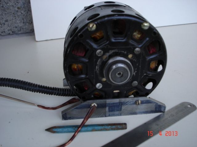
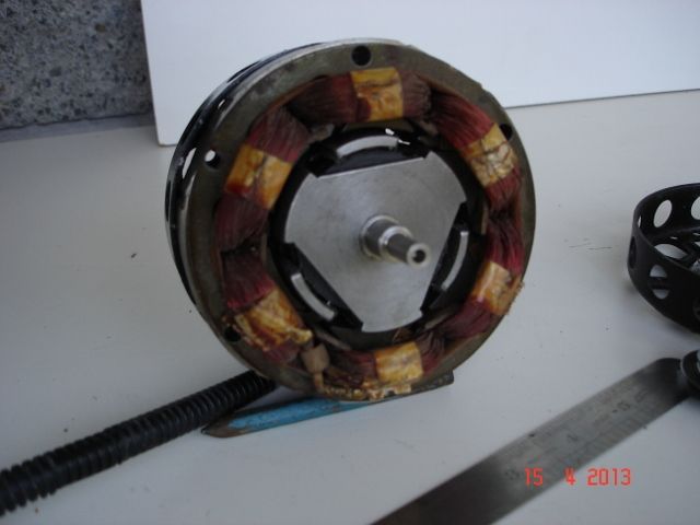
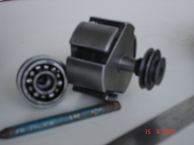
                                  Neil

                                  #260217
                                  John Olsen
                                  Participant
                                    @johnolsen79199

                                    Scrumpy, I presume you have a lathe available? You can try these motors out in the lathe, eg grip the shaft in the chuck and lash up something like a piece of wood to attach to the mounting plate to stop it rotating. Then you can try rotating it at various speeds to see what voltage you get. Hopefully you would know at least approximately what the speeds on a lathe are. You would need some sort of AC voltmeter. I suspect that they are going to need to go a bit faster than the 250 rpm you mention, but then if they are driven by a belt from the flywheel they can be geared up by quite a bit by using a small pulley at the alternator end. I have some small motors like this lying around, so I will take one out and have a play in the lathe

                                    The kV rating gives a guide to the rpm the motor will do at a given voltage, when driven by the usual ESC. It probably will give a rough approximation to the speed it needs to be driven at to generate a given voltage. A higher kV figure will mean that it generates a given voltage at a lower speed. (These are not kV as in kilovolts, they are rpm per volt.)

                                    The three phase rectifier is not a problem. it just means that there are six diodes instead of four. A simple way is to take two of the bridge rectifier units that are sold, and connect the two plus sides together, and the two minus sides also connect together. Then each motor lead goes to one of the AC in connections on one of the bridges Since there are four AC in connections, one of them goes unused.

                                    Perhaps Andrew can suggest a source for a suitable regulator and tell you how to wire it up. If you do need a heatsink at all, I would suggest the bottom of the water tank would be the coolest place on a traction engine, and out of sight too.

                                    Neil, the DC motor idea is fine, except they too tend to need regulation. Also brushes can be a bit of a pain, and they are often not very good on readily available small DC motors.

                                    John

                                    #260225
                                    John Olsen
                                    Participant
                                      @johnolsen79199

                                      OK, I just dug out a Turnigy G60-500, which is a 500kV motor, and ran it up on my lathe. Unfortunately I don't have a working tachometer at the moment, but working from the pulley sizes it would be doing about 900rpm. It gave 1.2 Volts between phases. Your 1100kv motor could be expected to give about twice that at the same rpm. The higher the kv, the lower the rpm it is going to have to turn at to generate enough voltage. Your 1100 would be a better choice than my 500.

                                      Current will not be a limitation, I tried shorting mine into an ammeter and got 13 Amps. If I wanted to use my one for a generator I would be wanting to rewind it with many more turns of finer wire, to get a higher voltage at lower speed. (The same motor is as mine is available in other kv ratings and that is what the difference is, the lower kv have fewer turns.) This would of course reduce the maximum current, but that is obviously far more than is needed. Your 50 LEDs at 20mA is 1 Amp.

                                      John

                                      #260242
                                      John Olsen
                                      Participant
                                        @johnolsen79199

                                        Sorry, I am getting things upside down…you want a low kV motor, that will give the required voltage at a lower rpm.

                                        Still, worth trying the ones you have to see if they will do the job.

                                        regards

                                        John

                                        #260276
                                        duncan webster 1
                                        Participant
                                          @duncanwebster1

                                          Looking at the motor spec sheet, the '500Kv' means 500 rpm per volt. This is when it is running as a motor, so as a generator it will want more speed. The rectifying diodes will drop 1.2v, so I'd expect somewhere around 1000 rpm before it showed any DC voltage, which agrees with John's measurements. It might be worth considering a 'joule thief', but I'll leave it to those more competent in electronics to provide a circuit. Alternatively, and this might be complete rubbish, how about using the LED's as the three phase rectifier. I know each individual LED will only be on for half time, but you can drive them a bit harder because of this, and persistence of vision means they will look a lot more than half brightness.

                                          #260301
                                          Scrumpy
                                          Participant
                                            @scrumpy

                                            Very many thanks to all who are giving me advice , have just run Shina motor it being a 920kv Outrunner in the lathe and I have the following results speed at 1000 rpm reading 1.7 v increased to 1500 rpm reading 2.1 v does this make sense to anyone I hope I have interpreted it all correct as this is all a black art to me if either of the motors will do for me there is plenty of room inside the housing to fit a regulator if this works I can fit a fan inside as well so heat should not be a problem ,

                                            With running the engine at 250 rpm with the correct pulley size I would imagine the motor would be into 3000 rpm is this okay

                                            #260304
                                            Muzzer
                                            Participant
                                              @muzzer
                                              Posted by duncan webster on 10/10/2016 13:15:14:

                                              how about using the LED's as the three phase rectifier.

                                              No, they don't like it up 'em. Max reverse voltage is typically only a few volts and I suspect the reverse recovery time will be very long.

                                              #260314
                                              Tim Stevens
                                              Participant
                                                @timstevens64731

                                                A permanent-magnet alternator is a fairly robust device. If you can find one with eg six windings around the stator, it may be possible to detach the windings electrically and use them in opposite pairs, with a switch to bring two, four or six into use. This would allow you to vary the output to match the load. Motorcycle 12v zeners are available, and will cope with about 100 Watts, enough to run the LEDs on a full-sized engine …

                                                Look closely at the workings of the small brushless motors used in models (not just aeroplanes) and you may well find simpler single-phase versions. In this design, all the magnets line up with a coil at the same time, whereas the 3 phase versions do it in sequence.

                                                If you could find someone local who played with motorcycle alternators in the sixties and 70s, make friends.

                                                Cheers, Tim

                                                #260330
                                                Trevor Drabble 1
                                                Participant
                                                  @trevordrabble1

                                                  Scrumpy ,

                                                  Would the Stuart Models dynamo be suitable , albeit expensive ?

                                                  Trevor

                                                  #260379
                                                  Neil Wyatt
                                                  Moderator
                                                    @neilwyatt

                                                    Schottky diodes are worth using.

                                                    Possibly why half-wave rectification was used?

                                                    #260397
                                                    Ian S C
                                                    Participant
                                                      @iansc

                                                      019 (640x480).jpgI have a number of generators and alternators, this is a 6 pole, shaded pole motor, modified with a permanant magnet claw type armature. The shading rings have been cut, but this makes little, if any difference. It uses 2 Ferrite magnets from old speakers, another source of these magnets is old Micro Wave ovens.

                                                      Ian S C016 (640x480).jpg017 (640x480).jpg

                                                      Edited By Ian S C on 11/10/2016 10:06:16

                                                    Viewing 25 posts - 1 through 25 (of 53 total)
                                                    • Please log in to reply to this topic. Registering is free and easy using the links on the menu at the top of this page.

                                                    Advert

                                                    Latest Replies

                                                    Viewing 25 topics - 1 through 25 (of 25 total)
                                                    Viewing 25 topics - 1 through 25 (of 25 total)

                                                    View full reply list.

                                                    Advert

                                                    Newsletter Sign-up