Building the James Coombes (with chips)
Building the James Coombes (with chips)
Home › Forums › Work In Progress and completed items › Building the James Coombes (with chips)
- This topic has 75 replies, 10 voices, and was last updated 19 July 2015 at 17:07 by
Nick_G.
-
AuthorPosts
-
17 May 2014 at 19:30 #31053
Steve Withnell
Participant@stevewithnell3442617 May 2014 at 19:30 #152791Steve Withnell
Participant@stevewithnell34426I've finally got started on my James Coombes build. Allan will twig what the "with chips" is about…
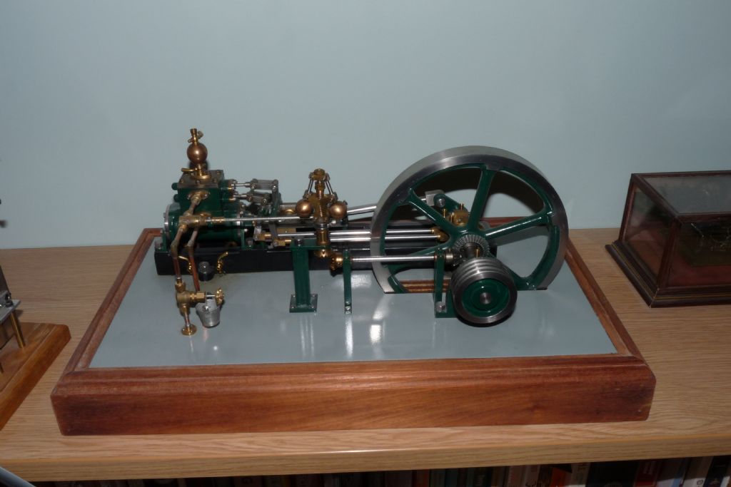
When I decided to build my first stationary steam engine, I had a very specific configuration in mind. It became very obvious that the Stuart castings and kits like the Victoria are versatile and can be used to build quite wide ranging variants.
My first attempt at a stationary engine was based strongly on the Victoria, but it has some features which are of my design and markedly different.
The James Coombes was configured from some existing Stuart castings and extrusions, then a few extra, like the boxbed, the cylinder caps and crankrod guides were created for the kit.
My Victoria was a long time in the making, mainly because of the time taken to work out the design and build of the bespoke parts. Although the Victoria was built and intended to run on steam, I 've only run it on air, I couldn't face stripping it down to clean out the water and gunk from the steam oil afterwards as it would be on the shelf for very long periods.
So, for the James Coombes, the plan was to build it straight out of the box, but include the governor. The cheap way to make the governor was to use the plan I have for the original governor kit and simply buy the fixings kit, which provides the balls and spring and of course, the fixings.
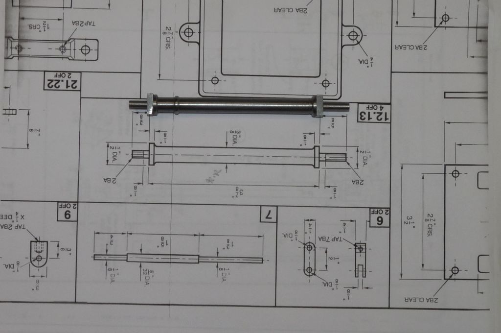
When I started reviewing the plans, I decided that the four columns that support the cylinder assembly could be improved by using square bar so that the machining would leave square "feet" at each end of a column and to add create the impression of a chapiter at the top of each column.
https://www.dropbox.com/s/guo4vldmcz75rh0/P1030609.JPG
This is the prototype column.
The work is in the early stages, but some photo's to be going on with:
https://www.dropbox.com/sh/zue22yuxsike8wf/AAC8rMwlh2m4e068NRjDTczga
I need to upload some of these to the forum so I can include the images in the post, which I'll do shortly. The Victoria was two years in the build, hopefully I can build the James Coombes to a shorter timescale.
Steve
17 May 2014 at 20:09 #152794 JasonBModerator@jasonb
Don't you go teaching Allan any of your dirty habbits

Look forward to following this one along.
J
17 May 2014 at 20:21 #152797Steve Withnell
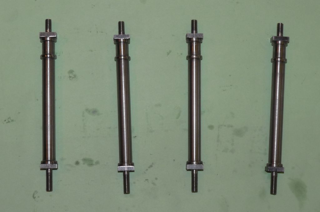
Participant@stevewithnell34426This is the prototype column, I sketched it out, machined it, had a think about the proportions
and then made four "production" components:
I'm afraid I missed out the lilywork and pomegranates, may be next time

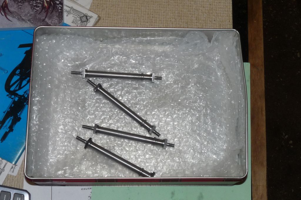
When I built my first engine, the Nemett 15S (the "Lynx" I think it is now called?) I'd make a part, admire it, then throw it on the bench, and move on to the next part. Stupid.
Now they don't get lost or damaged!
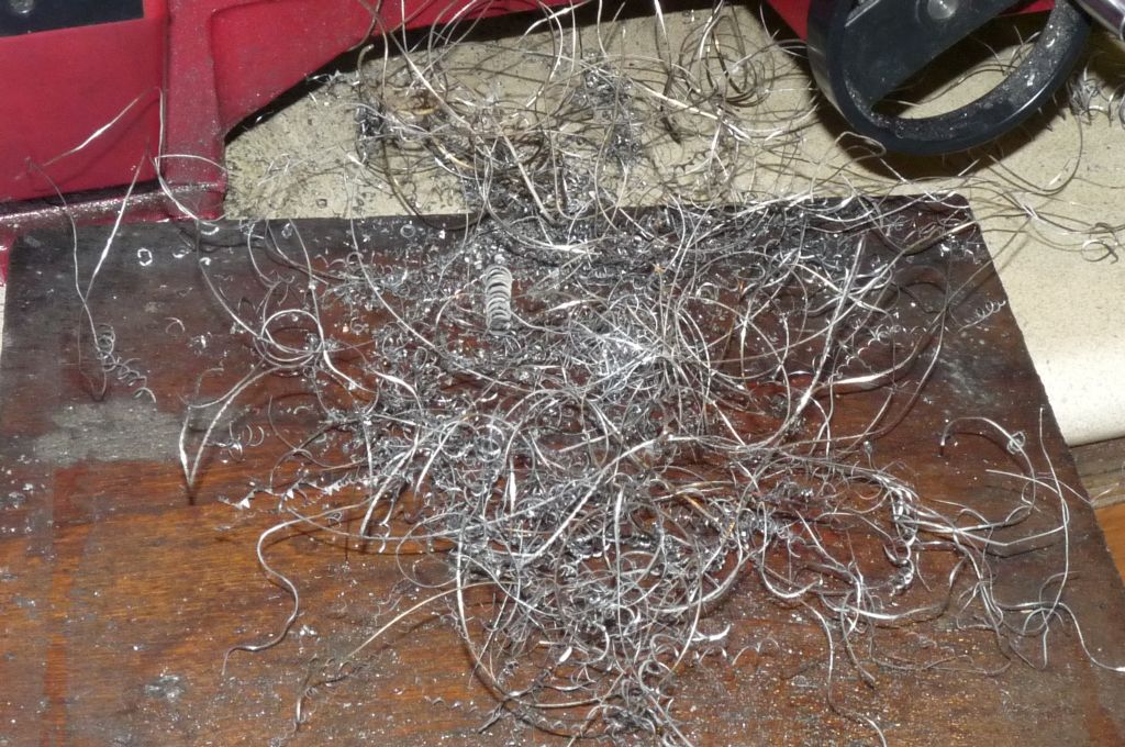
When Allan was posting the build of his Victoria, I often pulled his leg about the lack of chips in his photo's (hence the title of the original post). Here is a picture of just some of the material that was produced as a machined the columns. I made A LOTof this in the process.
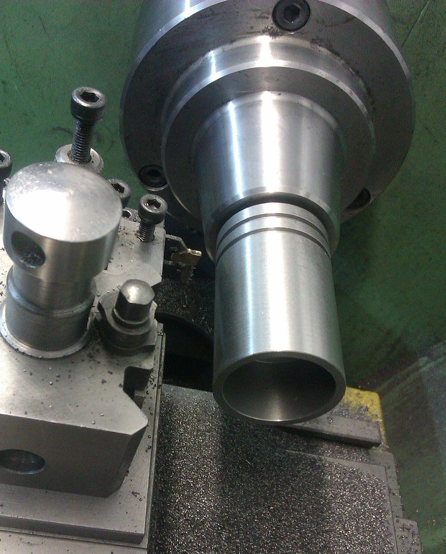
The serious point to make to folks just starting out, is that this stuff is razor sharp and you do not tug at it with bare fingers. The second point is that I used home ground lefthand and righthand HSS knife tools. The Lefthand tool in particular was suberb at removing material and producing a very nice finish. It did this by producing continuous lengths of this stuff at high speed, which can be dangerous (you really wouldn't want this wrapped around your nose!). One solution I've successfully used with a homemade boring bar is to grind a groove behind the cutting edge, which will break up the swarf and make the cutting operation much safer.
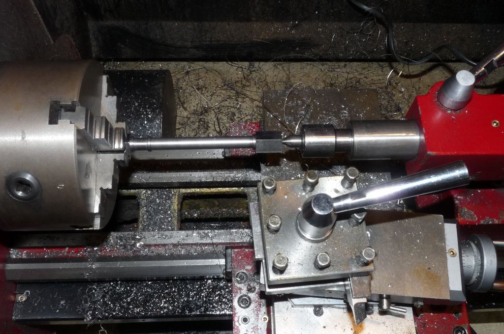
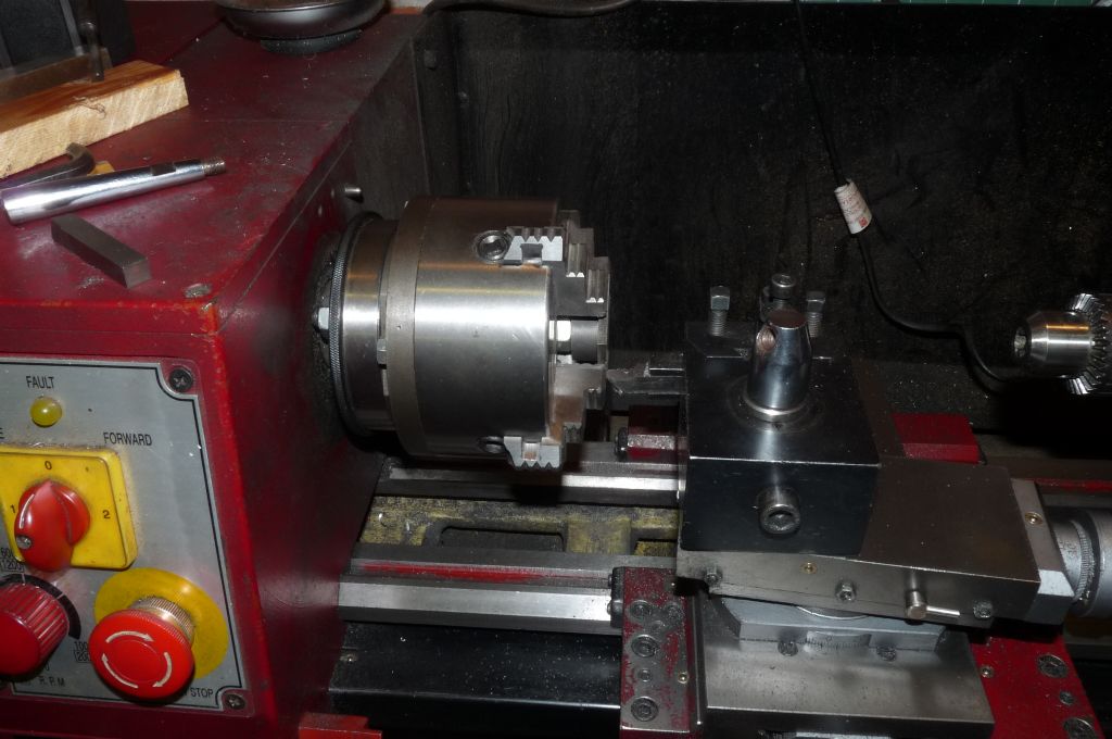
In the photo below, I've swapped my quick change tool post for a standard four way tool post and set up the LH and RH knife tools, which I think is a lot faster for this operation than the QCTP.
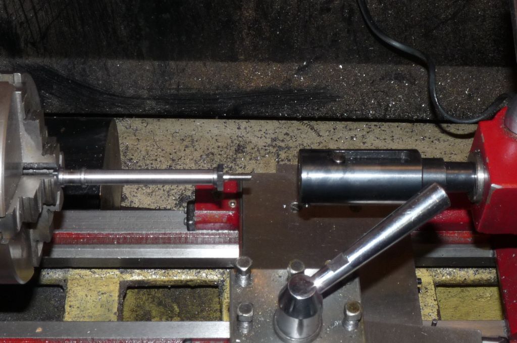
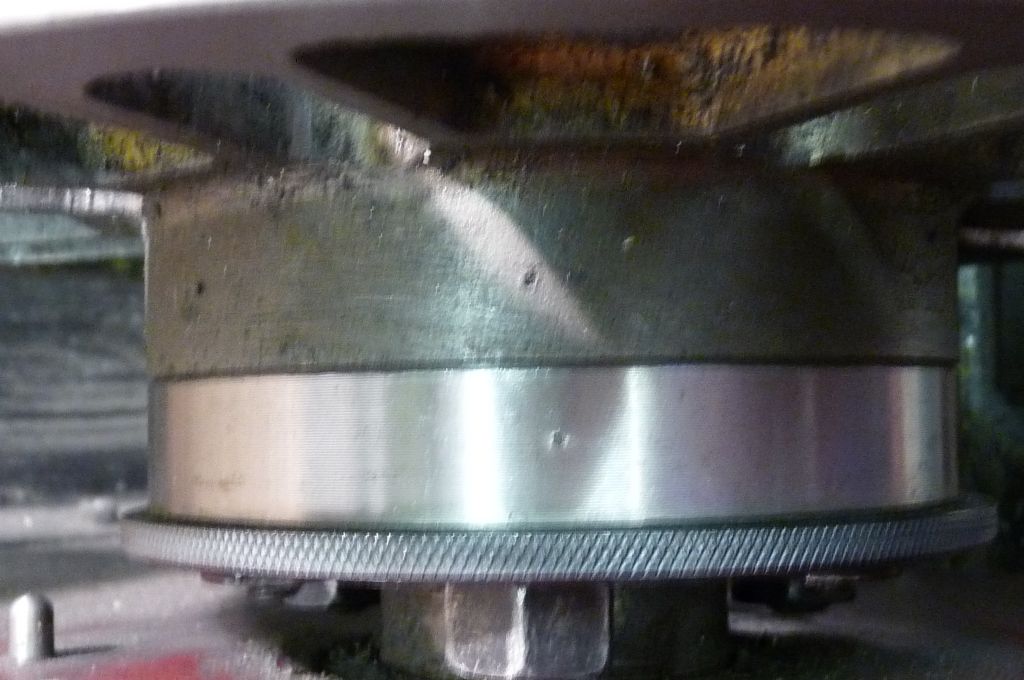
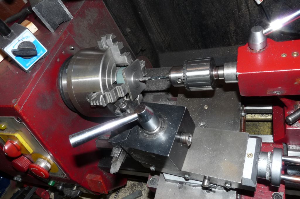
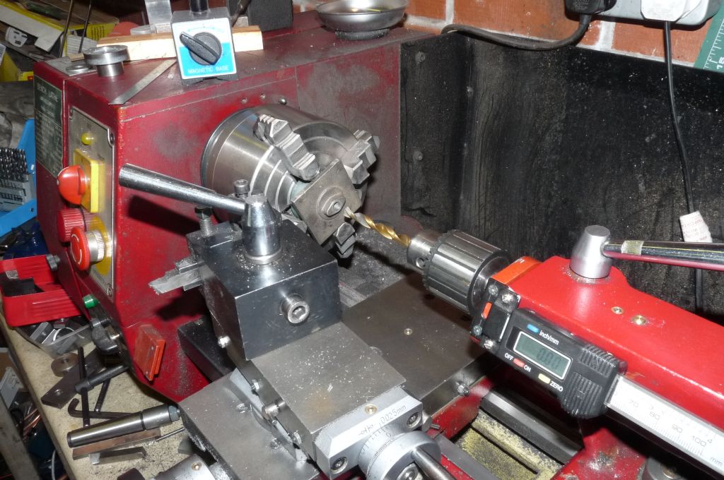
Cutting the threads on each of the column was done with a tailstock dieholder:
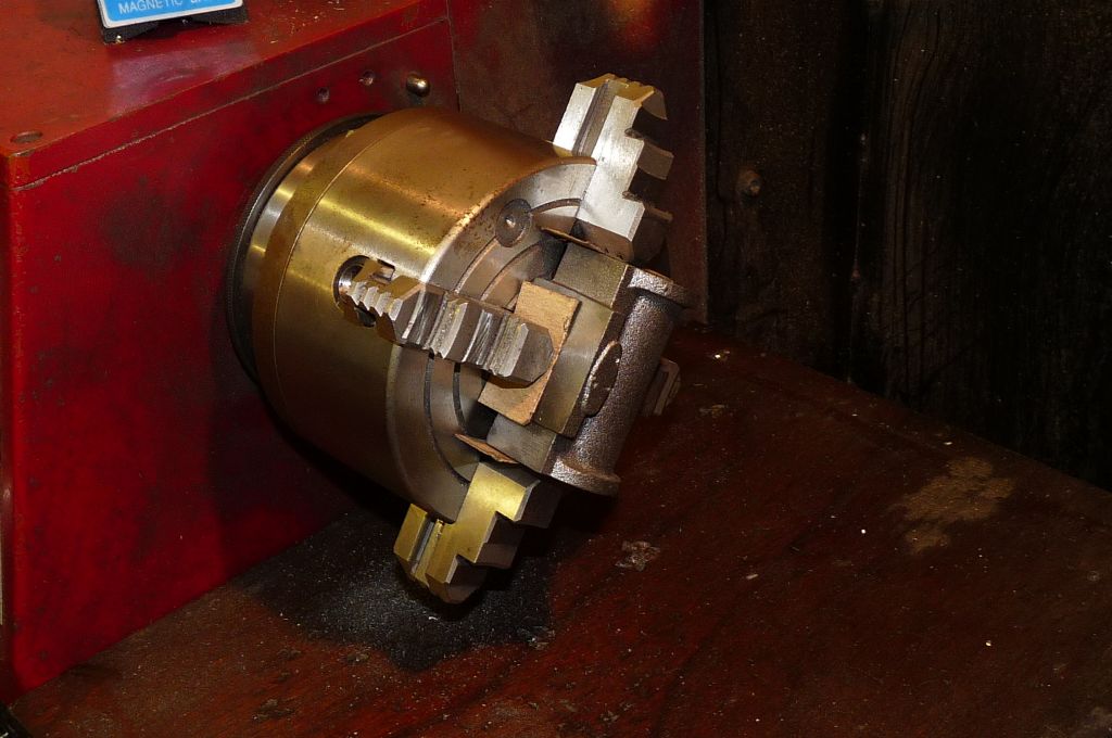
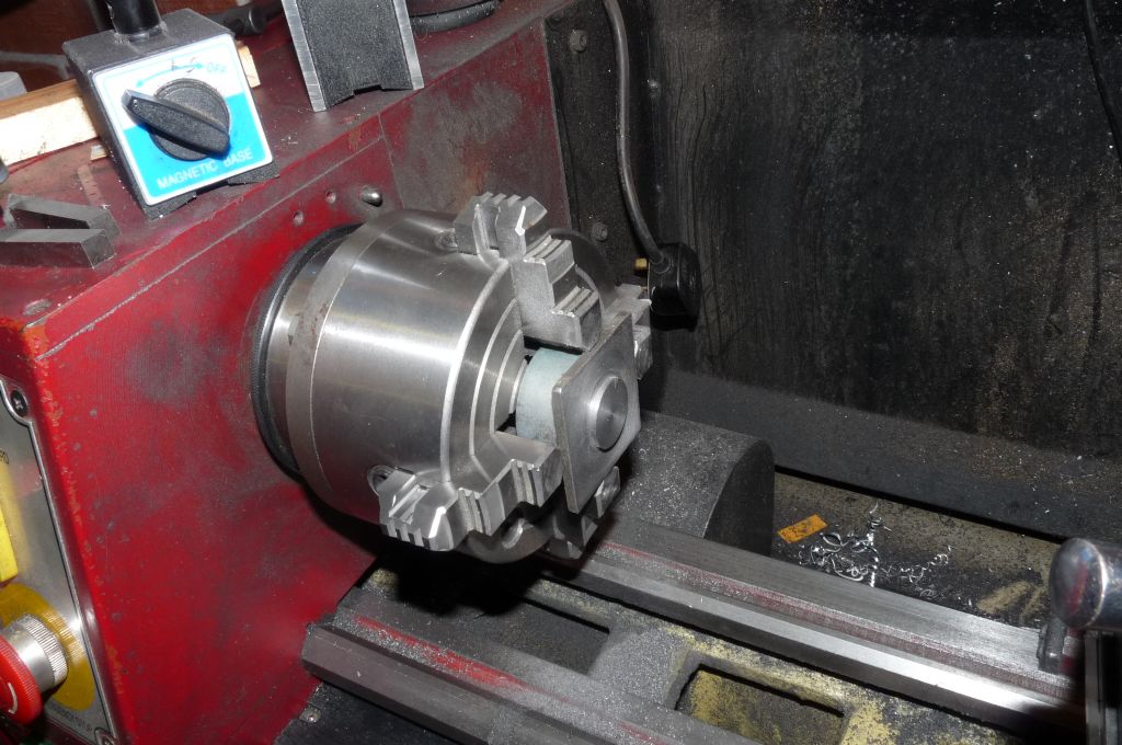
I did not cut the threads under power, but just spun the chuck by hand. The chuck by the way is a TOS four jaw self centering type. I bought this from one of the usual suspects for about £70, a real bargain, the only time I use the three jaw now is for hex bar.
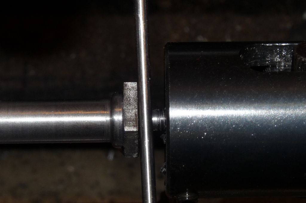
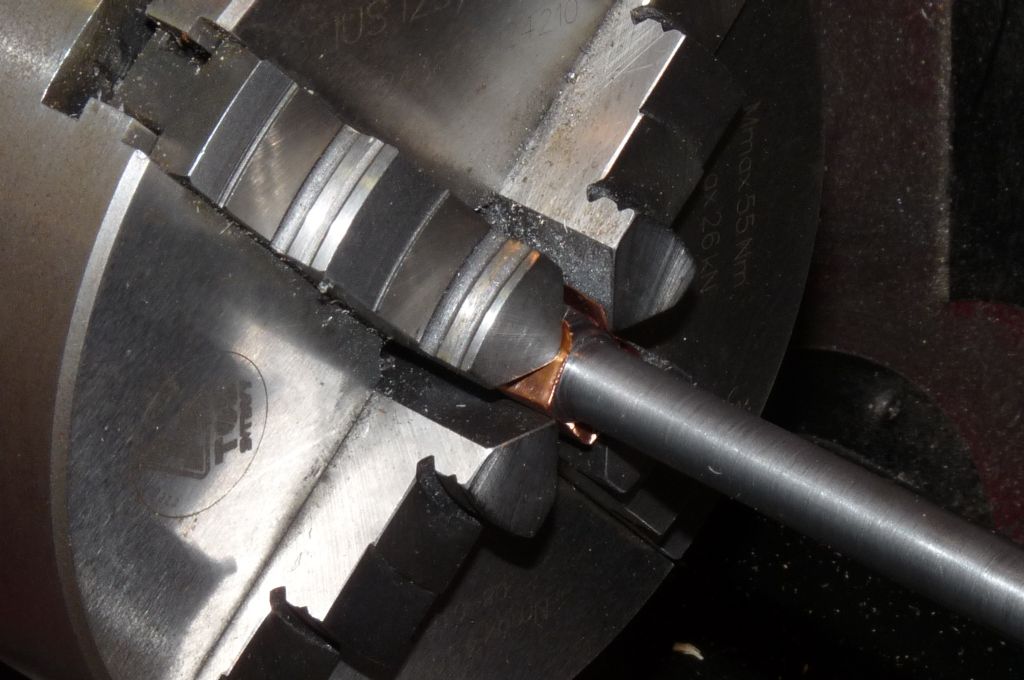
The mounting studs at the end of each column have a 1/8 inch shoulder, I measured this very simply by using a piece of 1/8 inch silver steel as a gauge:
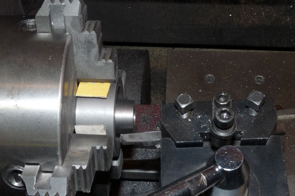
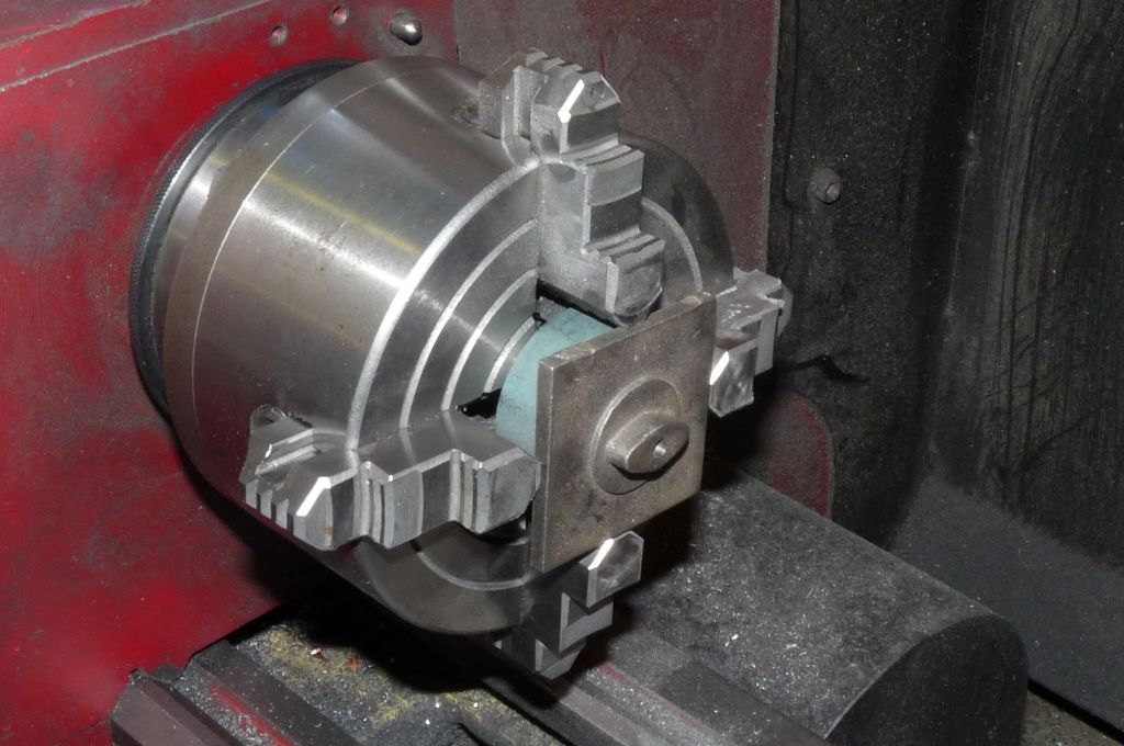
And the last thought in this post is to remember to protect components from damage when holding them in the chuck. You can just see the use of soft metal sheet (I had a bit of scrap bronze shim in the box) to protect the column from the chuck jaws.
Edited By Steve Withnell on 17/05/2014 20:28:04
18 May 2014 at 12:59 #152853GarryC
Participant@garrycHi Steve
This is great to see, I'm going to be following every bit. Great timing for me as well as I'll learn lots and lots from this I'm sure and no doubt it will help cut down the mortality rates on my no. 1 parts! Just as I was thinking this site couldn't get any better!
Now I just need to convert you into a chip free lifestyle..!
All the best with it.
Cheers.
Allan.
20 May 2014 at 00:53 #152983Nick_G
Participant@nick_g.
I shall be watching this one as I have decided that this engine is to be my first.

So come on Steve and get cracking so I have something to watch. Or I may even catch you up.!

Regards, Nick
23 May 2014 at 19:35 #153298Steve Withnell
Participant@stevewithnell34426Hi Nick – it will not be hard for you to catch me up! Personally, I think the Victoria is a better first Stuart engine than this one. You can always make the Victoria more complex – build the Stuart Twin or take a look at mine as examples (Google Steve Withnell Stuart Victoria for details).
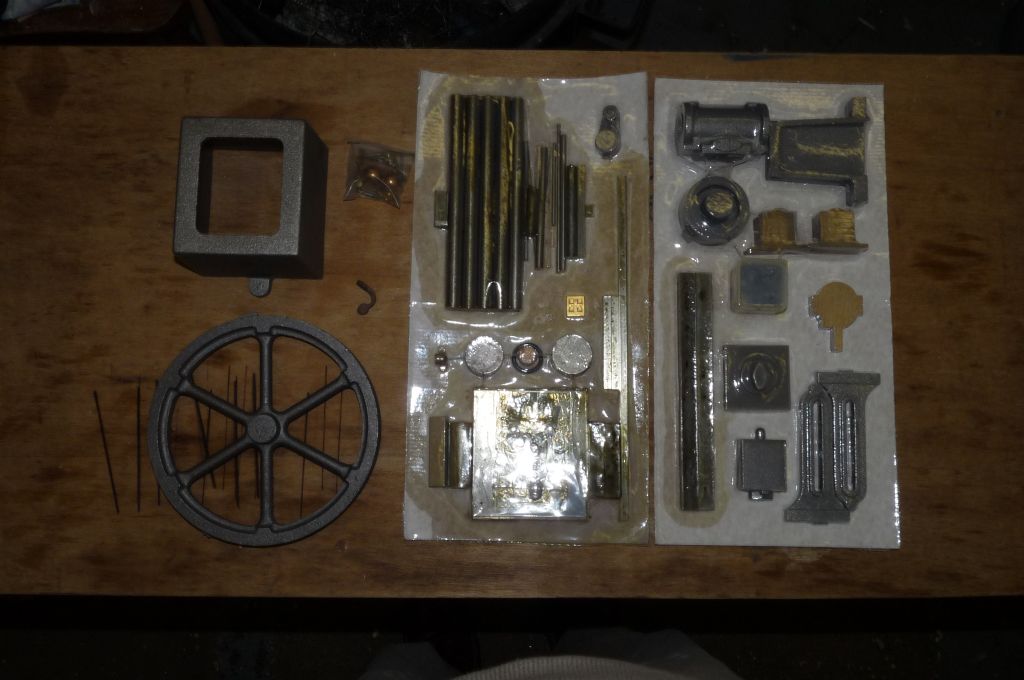
Anyway, back to the James Coombes – this is what is in the box:
I've also bought some bits to make up the governor. I do think these engines need a governor to be really finished.
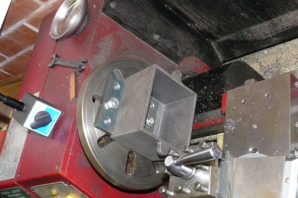
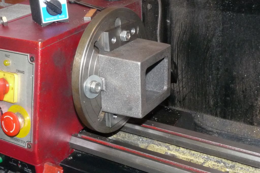
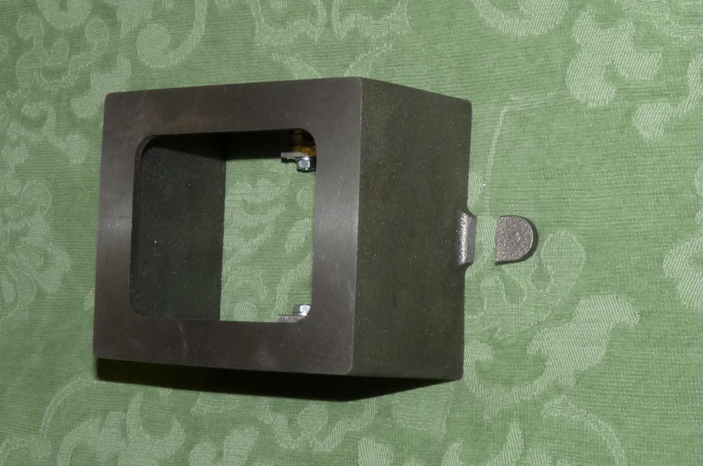
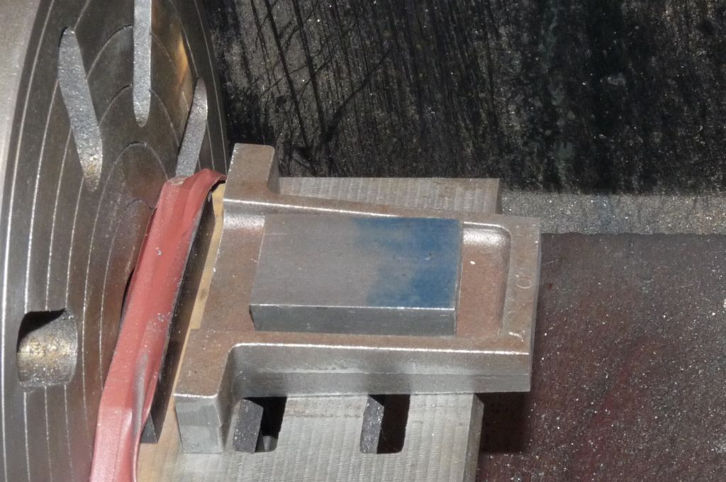
After the columns, I moved onto the boxbed. Standard approach – skim the base, turn over skim the top, all done. I decided to do this on the lathe, rather than the mill, the large square base looked easier that way.
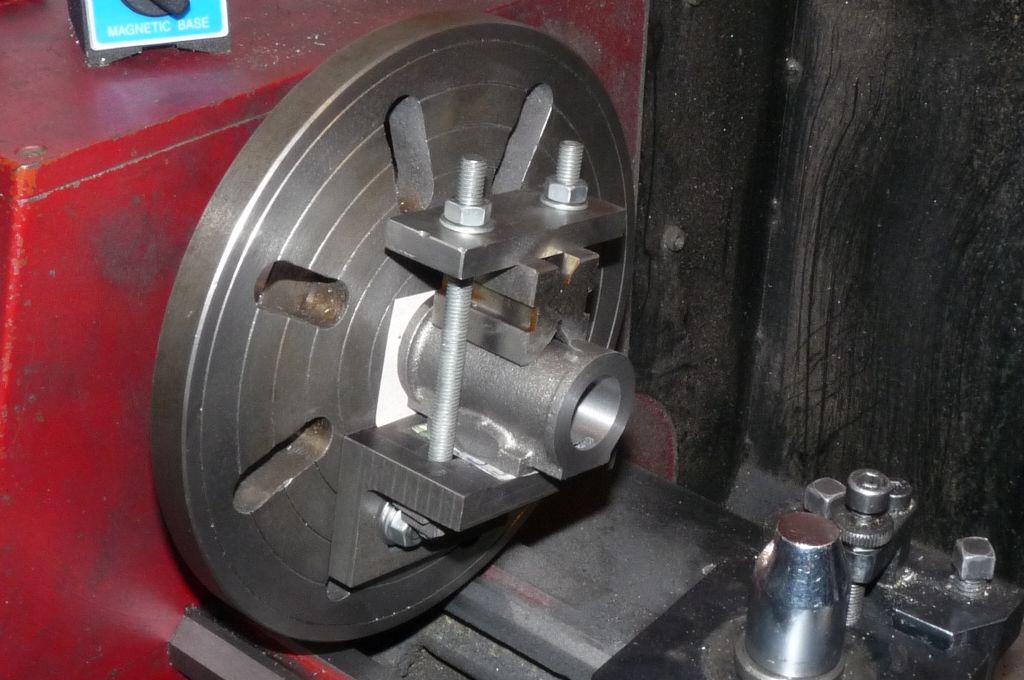
I discovered that the casting had some distortion, causing one of the mounting lugs to be bent downwards. The consequence is that if I had taken the bulk of the material is taken from the base, I would have ended up with very thin lug, so I decided to take more off the top of the casting.
By way of scale – this is a 9 inch faceplate. I used a standard carbide insert to do the machine. I ran the lathe around 200rpm. The lathe is a C6B variable speed job, but I fitted an additional low speed ratio for jobs like this. I didn't experience any vibration and did get a nice finish. The intermittent cut didn't cause any problems, as carbide is brittle and care has to be taken.
In order to get the boxbed to the right height, I had to sacrifice the rounded top of the boxbed, which I don't think will detract from the appearance of the engine. The height of the boxbed is important as one of the crankshaft bearings is mounted on it and the other is off-board, obviously the centre height of the two bearings must be the same for the crank to run freely.
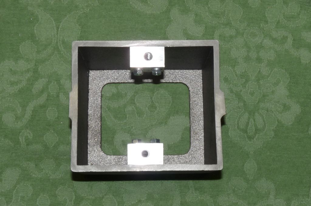
Slight accident – the deformed lug broke – I hadn't supported it properly as I tightened down the clamps. The way to solve the problem is to remove the other lug too –
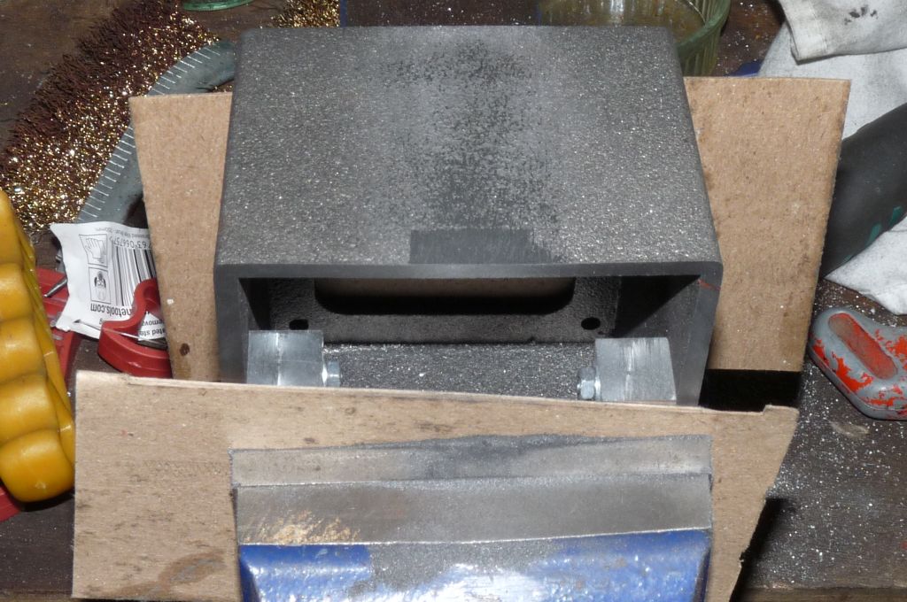
Then to add the lugs internally. The blocks are drilled and tapped 6mm. I installed the new lugs just proud of the base and then skimmed them flush. At the right hand edge, the distortion is just visible. I think getting rid of the external lugs will improve the look of the finished engine. In actual fact, the prototype model that Andrew Wilson built, had the lugs on the inside.
Finally, the old lugs are filed off flush with the body and this component is complete.
23 May 2014 at 20:36 #153306NJH
Participant@njhWell done Steve!
I will be following your build with interest. I do like the look of the engine – in fact I'm part way through ( and I have been for a long time!) Anthony Mount's Trapezium Connecting Rod engine which is similar in many respects. I'm sure I will pick up a few tips from your build. If your Victoria is anything to go by, your work is very worthy of imitation!
Cheers
Norman
23 May 2014 at 21:01 #153315NJH
Participant@njhP.S. What have chips got to do with it?
N
23 May 2014 at 21:26 #153318Steve Withnell
Participant@stevewithnell34426It's to do with Allan's thread on his Victoria build. In his photo's, his machines are always immaculate, so from time to time I'd ask him where the chips where. My machines are not immaculate, hence the chips!
Steve
24 May 2014 at 13:20 #153383Ian S C
Participant@ianscI think a lot of blokes on this and other sites have two workshops, one that we don't see where the work is done, the other where the photos are taken. Good work Steve. Ian S C
28 May 2014 at 20:29 #153813Steve Withnell
Participant@stevewithnell34426A bit of a dilemma. I set out to build the James Coombe straight off the plan, but made two changes already!
I've started work on the cylinder and it is identical to the Victoria. The steam ports are 1/16 in from the ends of the cylinder. The cylinder end caps for the Victoria have a 1/16 thick boss so when they are fitted to the cylinder, the steam ports are at the very ends of the enclosed cylinder.
On the James Coombes plan, the bottom of the cylinder (the end without the piston rod) is fixed directly to the table plate, so there is a 1/16 gap between the bottom of the enclosed cylinder and the steam port.
In Andrew Wilson's book "Building the James Coombes…" he describes making a spigot 1/16 thick, 1 inch diameter with a 1/4 inch peg on the underside to be a press fit into the table plate, this allows for accurate location of the cylinder before drilling the fixing holes around the cylinder flange. This spigot is a permanent addition an will also serve to eliminate the 1/16 gap between the plate and the steam port. Andrew Wilson doesn't comment on this latter point in the book.
"How" isn't a problem, but will the effort of making the spigot actually make a material difference to the engine when it is running? Also, given how the spigot is fixed, will this cause problems over time? Stuart clearly didn't think it necessary when revising the plans.
Regards
Steve
28 May 2014 at 20:39 #153814 JasonBModerator@jasonb
For an engine that is just going to sit on a table ticking over and looking nice I doubt the difference in volume will make a lot of difference, you could always make the piston rod 1/32" longer so you have equal voids at each end.
The spigot will ensure the cyl always goes back in the same place, depending on how much clearance there is between the studs and the holes will allow a bit of movement without the spigot. I suspect the advice to use the spigot to locate the cyl for drilling was before we all had DROs on our machines and so was more useful then than it may be now.
J
30 May 2014 at 21:04 #153946Steve Withnell
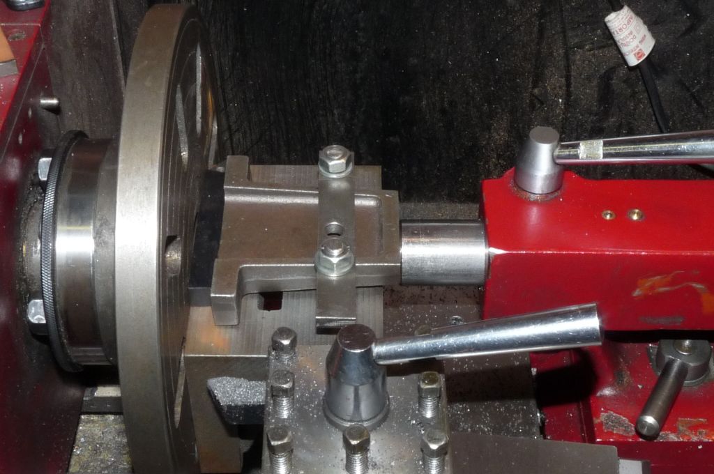
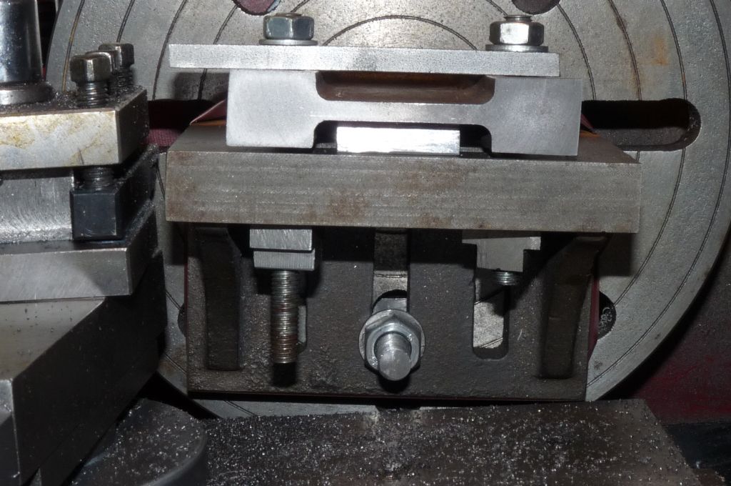
Participant@stevewithnell34426After completing the box bed, I progressed onto the off-board bearing mount. This component has to have a finished height of 3 inches so that the bearing will end up at the same height as the bearing on the box bed. It's a straight forward job on the lathe, except that the sides are tapered, so it cannot be clamped directly to an angle plate.
In this photo the casting is pressed against a packing piece, but you can see the front edge is not in contact with the angle plate. Using the tailstock to keep pressure on the workpiece during clamping is a neat trick someone on the forum told me about, but can't remember who! It does work.
In this photo, I've shown the packing piece underneath the workpiece. It turns out that the web is actually parallel to the vertical axis, so it can be used as a reference, so this is what is used to clamp against, just needs the packing piece. I've also taped down the packing piece to ensure no unexpected departures from the angle plate.
Finally, the workpiece clamped down against the web
The packing piece has to be clear of the radiused edges of the web. I'm not going to drill the bearing mount until I've completed the bearings themselves, as I will spot through from the bearing into this mount.
Edited By Steve Withnell on 30/05/2014 21:05:53
31 May 2014 at 15:52 #153987Steve Withnell
Participant@stevewithnell34426So the next components are the two flat plates, one forms the top of the boxbed and the other the "entablature" itself, that is the table the cylinder is mounted on. (That's why it's called a table engine, not because it sits on my table while I admire it

These plates are 3/16 steel from 4 inch wide stock. They are close to size in the box but cut edges do need a bit of filing to square off, which brings them to size. I did think about skimming the edges in the mill, but not sure it would be worth the effort.
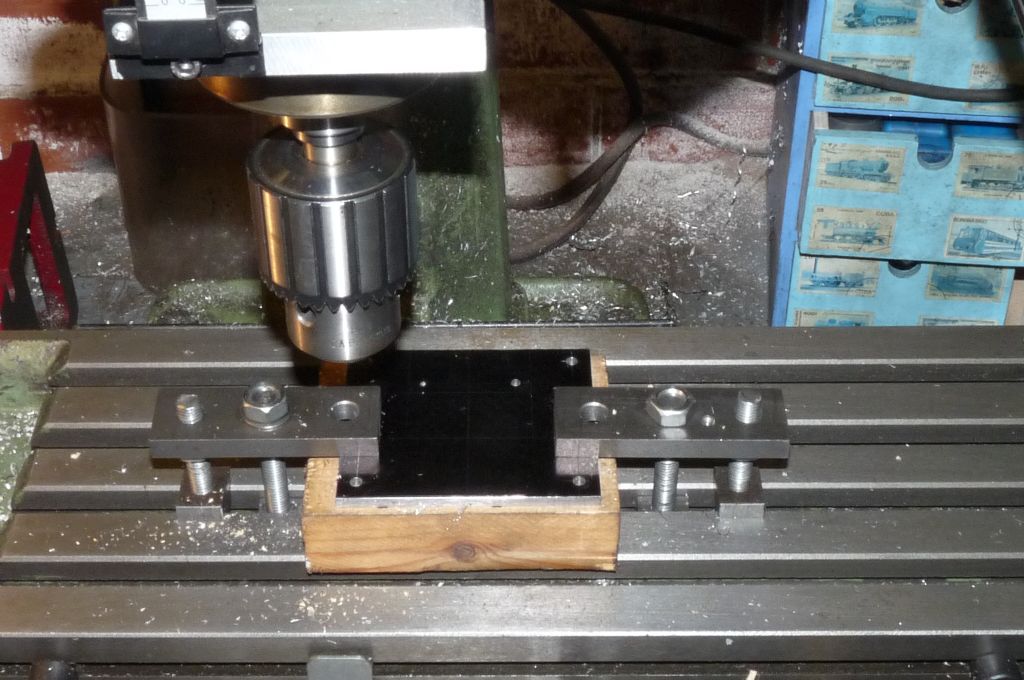
The plates were "painted" with a big dobber permanent marker and then marked out as per plan.
Here is the first one being machined:
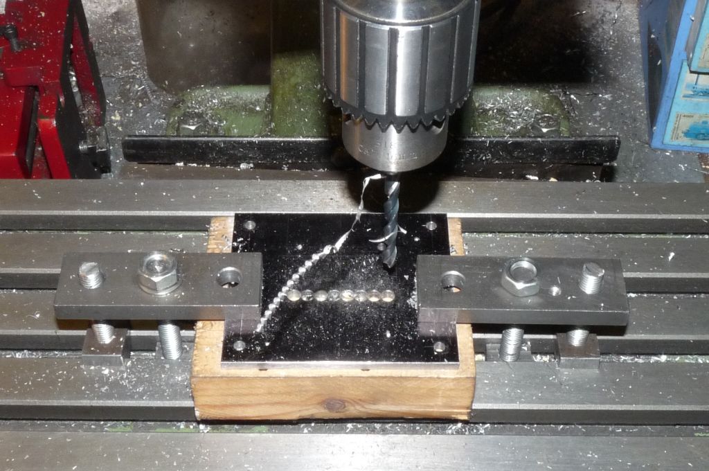
I'm just using the mill as a decent drilling machine. I'm simply working to the marking out, the hole centres have been centre popped.
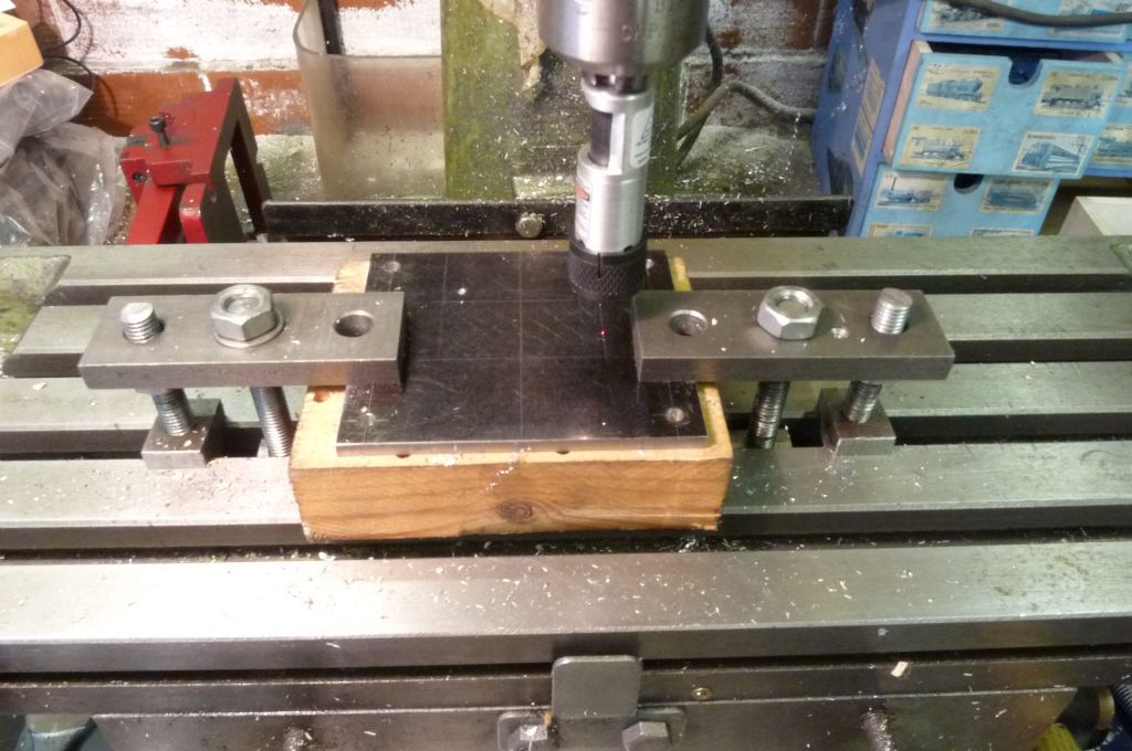
There is a decent size slot to cut, so this was chain drilled, pretty accurately – I used a 6mm drill and moved the drill on 6mm each time, taking care to stay just inside the marking out.
A 6mm drill is slightly undersize for this operation, a slightly larger drill would have been better. The 6mm drill doesn't quite fill the area to be removed.
Before I started to chain drill, I used a laser centre finder to make sure the plate was properly aligned. I bought this thing on impulse at Harrogate one year and it's great for aligning edges (like a mill vice jaws and marked lines), but I really don't trust it for finding centres and don't use it for that purpose. I think there are better uses for £60.
The chain drilling in progress:
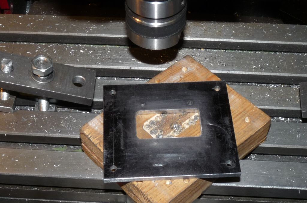
The holes just touch so once I've been round, a touch with a cutting disc in the dremel, and I can lift out the waste material. (Is it safe to say "waste" in this community?) Some magic happens with a 6mm slot drill and the bottom plate looks like this:
The sharp eyed will spot one of the drilled holes is not right – the tip of centre drill broke off – I fixed that by drilling from the other side, I used a smaller drill to allow for any misalignment, then used a small punch to knock out the offending HSS. I then drill the hole the correct size, from the right side of the plate with the final size drill without problem.
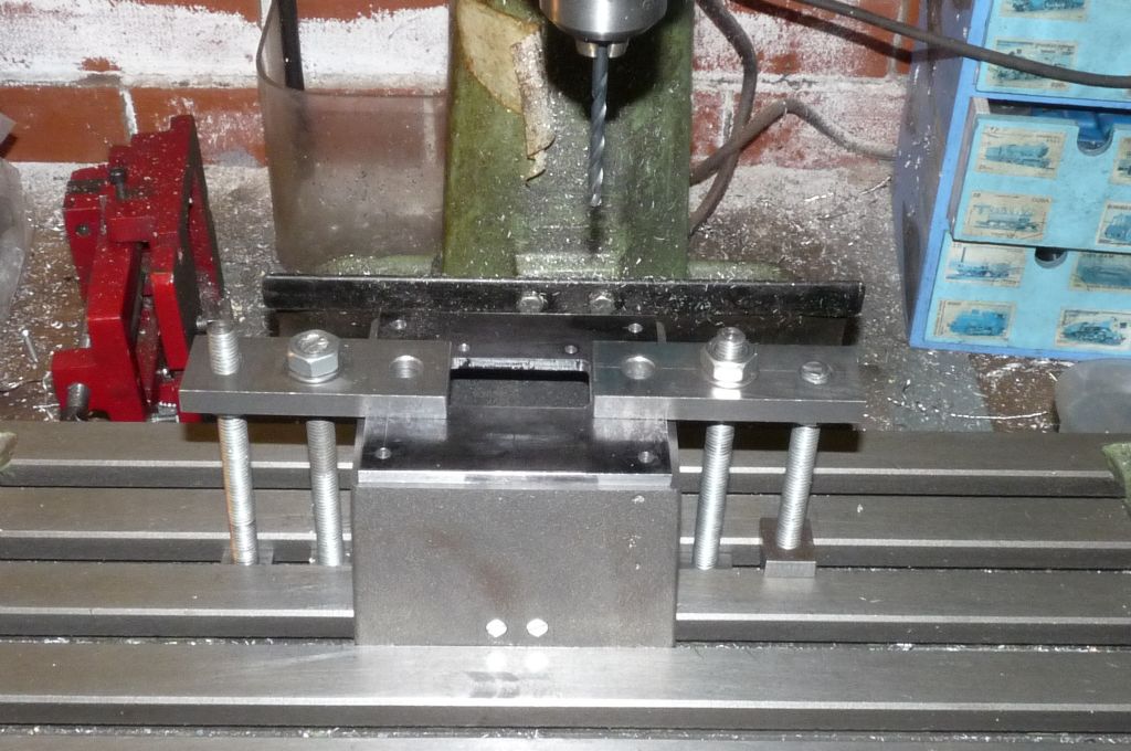
Finally, spotting through to the boxbed to ensure the holes line up:
The top plate – the "Table" top is the same, but with two narrow slots for the dual connecting rod arrangements.
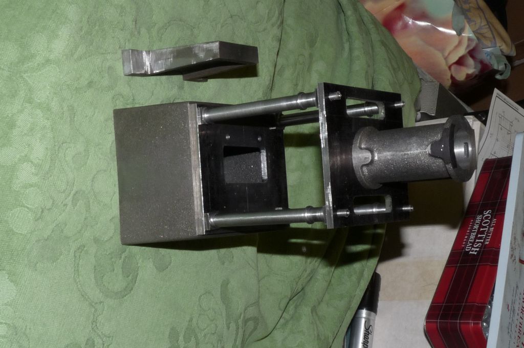
At this point I couldn't resist putting the bits together – apologies but forgot to rotate the image before uploading

I started this build by making what I thought were a bit of personalisation of the columns. Actually, I've "mixed me' sel a bottle" with those square feet. The consequences will become obvious a bit later. Next installment, machining the cylinder.
Edited By Steve Withnell on 31/05/2014 15:53:20
Edited By Steve Withnell on 31/05/2014 15:54:29
7 June 2014 at 09:10 #154637Steve Withnell
Participant@stevewithnell34426Next step is to machine the cylinder, I followed the method described by Andrew Wilson in "Building the James Coombes". It's the same method as for the Victoria, it is the same cylinder.
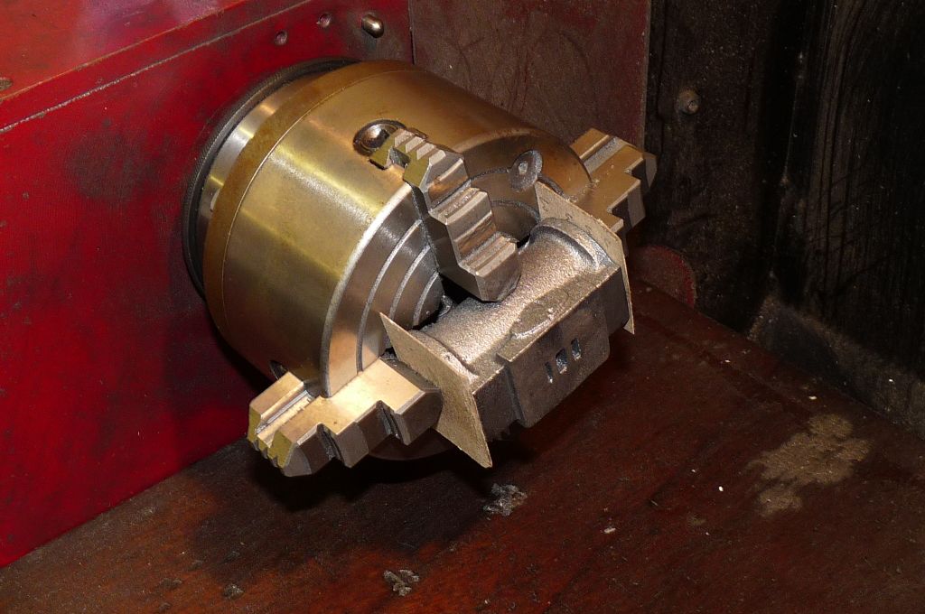
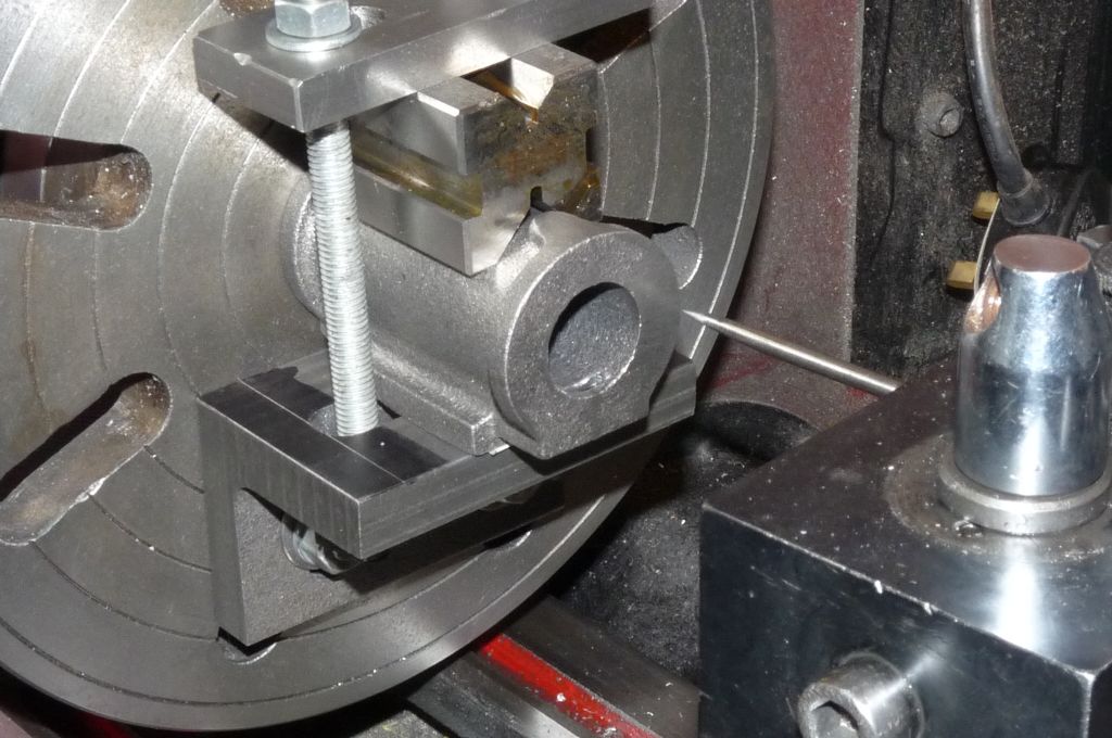
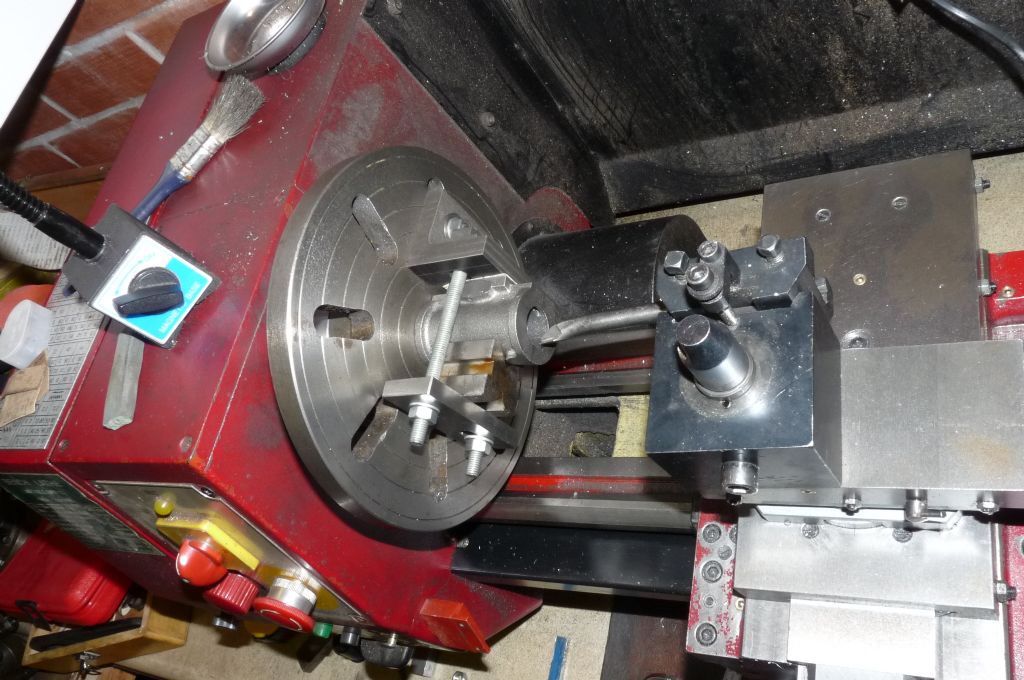
Once the cylinder casting has been cleaned up, then the cylinder is set up in the four jaw chuck using the jaw slots as pseudo V-blocks
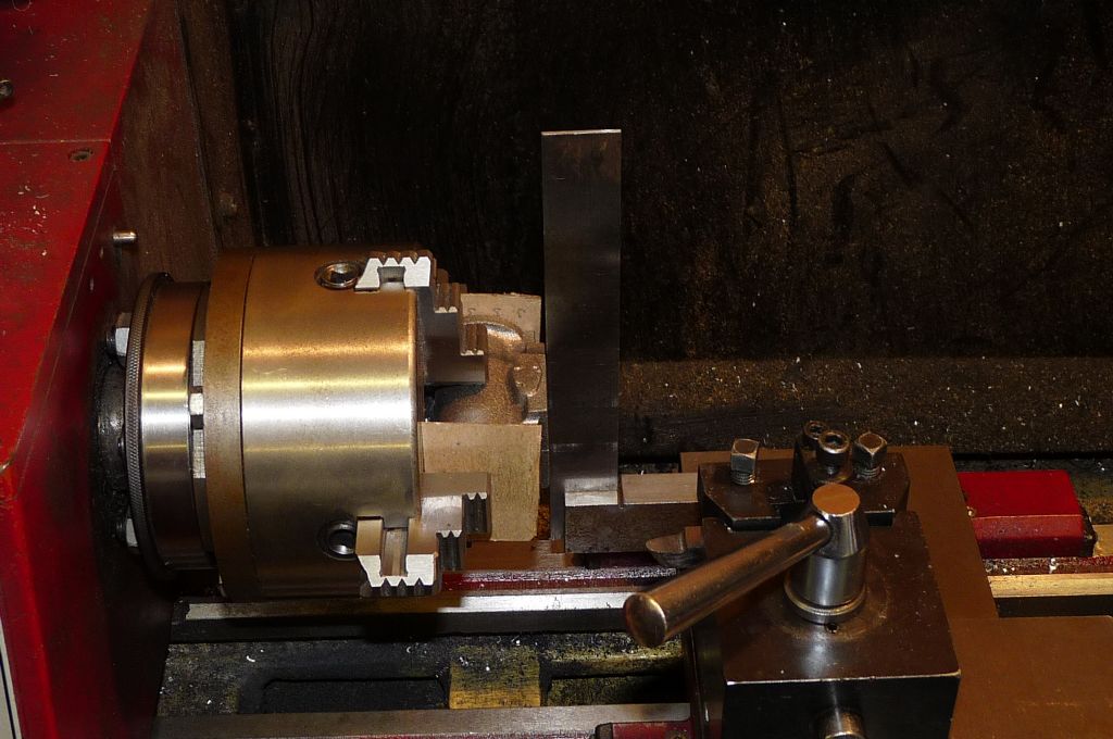
The port face is set square by using a set square on the cross slide –
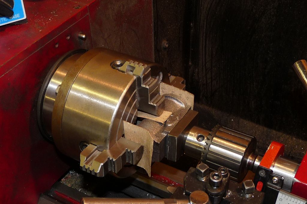
Again using the tailstock to make sure the workpiece is properly seated in the chuck –
Thin card being used all the while to prevent the jaws damaging the softer cast iron. The port face only needs a light skim, to bring it to dimension.
The actual ports are a bit untidy, so these I cleaned up with a needle file, but it's quite difficult to get them to plan.
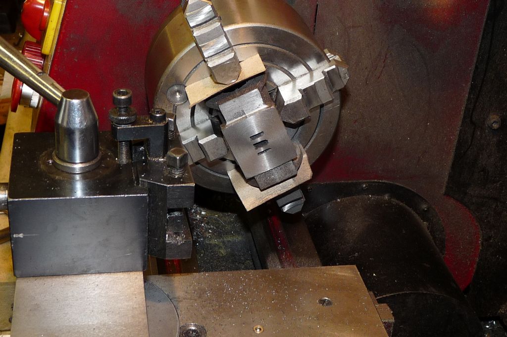
Next step is to skim the exhaust port, this is done by rotating the cylinder through 90 degrees, the port face itself is now used as a datum. (the port face and the exhaust port should be at 90 degrees).
Here you can see how poor the port face is, from what it needs to be. There is plenty of material to go at to get to a decent finish. The thing to be careful of, is that the tool is used between the flanges, so important to take care not to hit them as the cylinder is whizzing around.
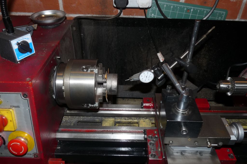
Just a couple of notes on my lathe. I have a centre pop mark on the spindle, in this photo you can also see a matching pop mark on the back of the face plate. Once I'd had the face plate a couple of years I centre popped the back, then took a light skim right across. The intent, if not the reality, is that provided I'm scrupulous about keeping the mating faces clean, the faceplate should run true. I use the same technique with all my chucks too, though not the independent 4-Jaw, to minimise the run-out. Chuck back plates are not expensive for this machine and ir's not hard to machine them in-situ to achieve minimum run-out. Given the runout on my first lathe chuck was 1/16 and I still managed to make a cylinder and piston set, It's not something I obsess about.
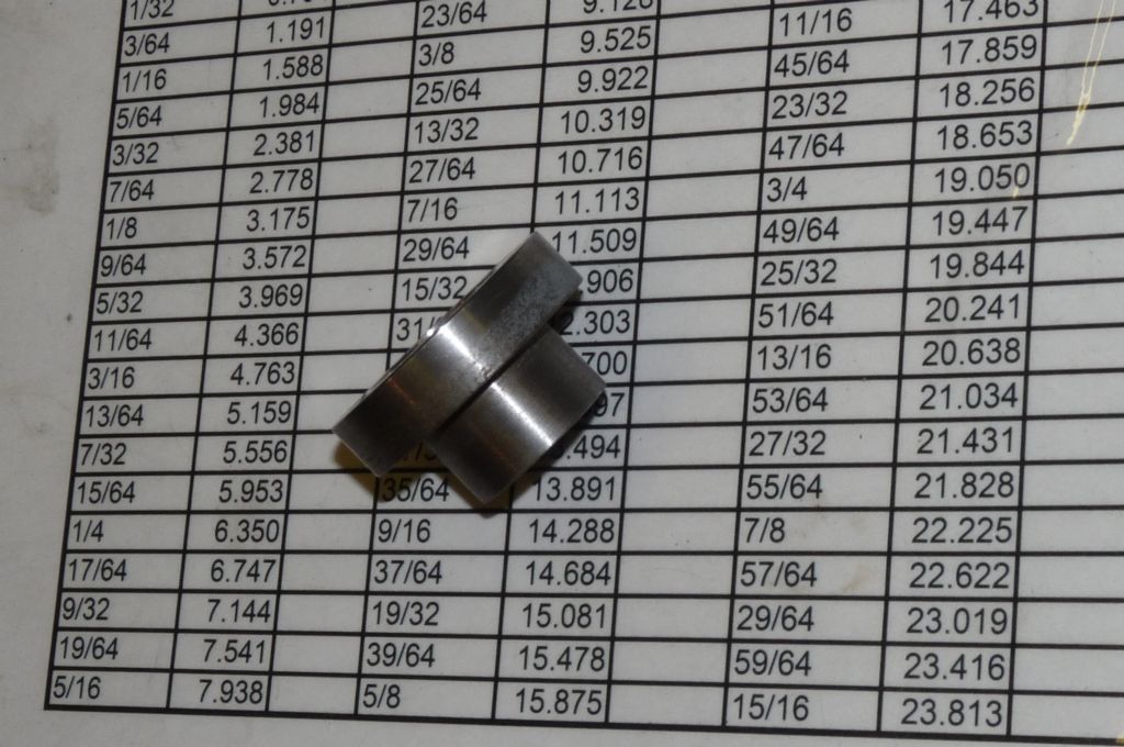
Final piece is this –
Two points, my machines are all metric and Stuart kits are imperial, so I use excel to make and laminate conversion charts. The little fixture I made for the Victoria and I pretty chuffed with it to be honest. The plug end is turned to 25.4mm to act as a gauge for boring the cylinder to size, the top flange is a drilling jig, it has a series of 7BA tapping size holes to make drilling the cylinder easier. Last part its that I have turned a recess into the large end which matches the cylinder cap boss, so it can be used as a drilling jig for the cylinder caps. A lot of value from a 30mm length of EN1 ! I'll show this little jig in place when I write up the boring operation.
7 June 2014 at 10:27 #154638Steve Withnell
Participant@stevewithnell34426Moving on now to boring the cylinder. I find this is the most frustrating set up to get right. The bore obviously needs to be on the centre line of the cylinder and concentric with it – the bore needs to be correctly centred at both the front where the bore starts and at the back where the bore exits- the casting must not be "looking up" or down or left or right and must be properly centred. Here is my set up –
I'm using the port face (you can see it is just sat on some thin card to protect it). This should mean the casting is not looking up or down but facing down the centre line. Using the scribe, I'm then setting the height of the bore so that it is centred on the edges of the flange – this is the part of the casting which will not be machined, so the bore has to be set in relation the nominal centre of the flange.
Having set the height, I then needed to ensure the casting isn't 'looking left or right' I chose to use a little V-block that would just sit on the cylinder, so again, aligning to a part of the casting that would not be machined. The studs get in the way of using a single set square against the faceplate though.
Once I've got the setup the best I can (there are no absolutes with the cylinder casting, which always makes me uncomfortable), which takes ages, I then get ready to bore the cylinder –
This is a home made boring bar, silver steel, heated, bent, ground, hardened, ground, honed, I find making these things quite therapeutic and you get the tool for the job, with little compromise. The overhang is set to just clear the bore and the faceplate centre hole is larger than the bore, so nothing to worry about with the boring. I find that sharp tools run at slow speeds with light cuts make nice bores.
7 June 2014 at 13:00 #154647Steve Withnell
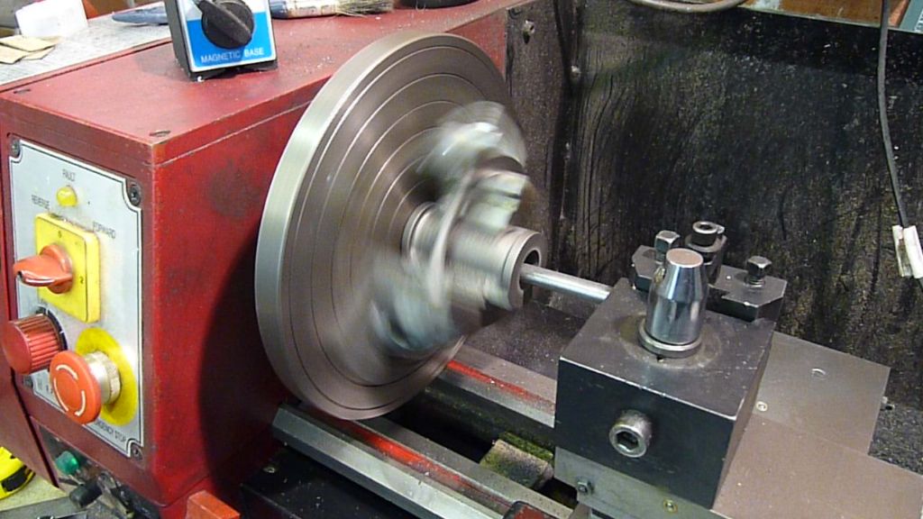
Participant@stevewithnell34426So boring in action, all sound and fury –
It's a big file, so don't click the link if you are on 9.6K dial up

The spindle speed is around 150rpm I think.
As per the previous post, I made a little plug gauge / drilling jig for these cylinders, here you can see the holes and the recess for the cylinder cap. At this point the gauge is a push fit, there is some resistance to entering the bore. The trick I use to getting to size is simply to "test" a new cut I put on, by just boring a little way (<1mm) and checking with the plug gauge, if it doesn't fit, I take the cut and then repeat. If I've put a bit much on, I can back off the cut a bit and try again. This way, if you do go oversize, there is only a small fraction that is oversize and doesn't spoil the job.The conventional wisdom is to take a number of cuts at the same setting to finish off the bore. I've found that once I've made a number of very light cuts, the effect is the same. The gauge fit the same both ends when I'd finished.
Once the bore is the right size, then I faced off the cylinder with a round nosed tool. At this point the flange face and the bore are at 90 degrees to each other and will be the end we use for the piston rod to enter as the other end is less likely to be as true.
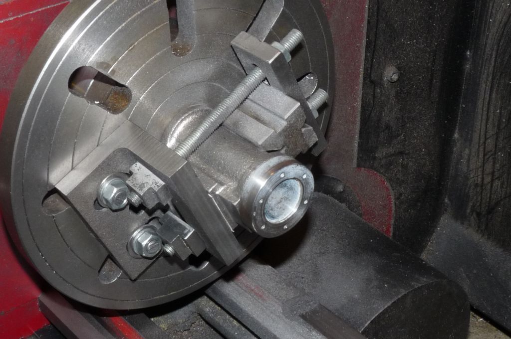
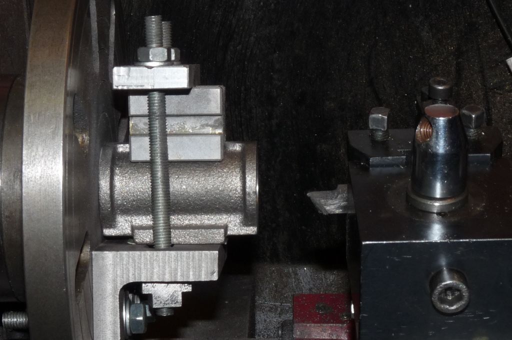
Now the cylinder is turned around with the machined flange against the faceplate, protected with thin card, this should mean the two machined flanges are parallel.
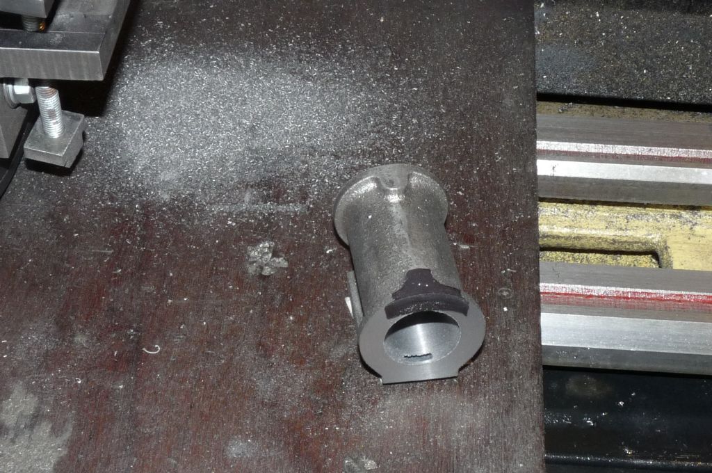
Finally the cylinder can come off the machine – here I've marked the front flange in black marker and also put a little centre pop mark in the top of the casting, so I know which end is which
The machined portface is sat on a piece of card… I'll clean the lathe up, the cast iron makes a real mess and gets everywhere. It also makes an excellent grinding paste when mixed with the way oil, so it really must not be left. I know some folks cover the ways and saddle with a cloth to keep the horror out of the machine, I did try that once, but spent more time worrying about the rag getting caught in the work than I did about getting a good job done. Although I leave a bit of slack in the drive belt, the lathe still has plenty of torque to do damage a low speeds.
Next installment is the drive pulley. Should be a bit more straightforward.
 8 June 2014 at 08:54 #154741
Steve Withnell
Participant@stevewithnell34426Off we go with the drive pulley. This is a real lump of cast iron and I started off by filing off the rough. I've mounted it in the four jaw chuck, gripping it by the hub. The hub is tapered, so not a great place, but good enough and it is all that there is. The bits of card serve two purposes, one to prevent the jaws damaging the hub, but they also act as an early warning that the tool is approaching the chuck jaws. Bits of card start to accumulate on the tip of the tool just before you get to the jaws.
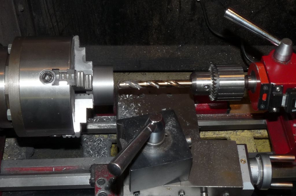
I kept the depth of cut quite light to avoid the pulley being ripped out of the jaws. Next job is to drill the hole through the pulley centre. I did this in three – first a centre drill, then a 6mm drill then a 10.8mm drill. Finally a 7/16 machine reamer to take the hole to size. You can see in the following picture that the card has been cut away. (And not the jaws!)
What I've not show here is facing off the end of the pulley and the hub, but that's a very simple operation. In this photo, I've reversed the pulley and clocked it true. The ends of the pulley have been faced off, but here I'm actually turning the hub to a clean taper instead of the raggy 'as cast' finish. This means the hub and the pulley outer are concentric. I've also cleaned up the in inner recess of the pulley, again to make everything nice and concentric.
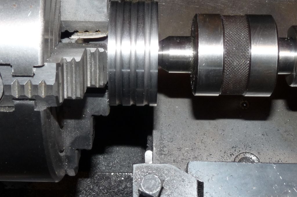
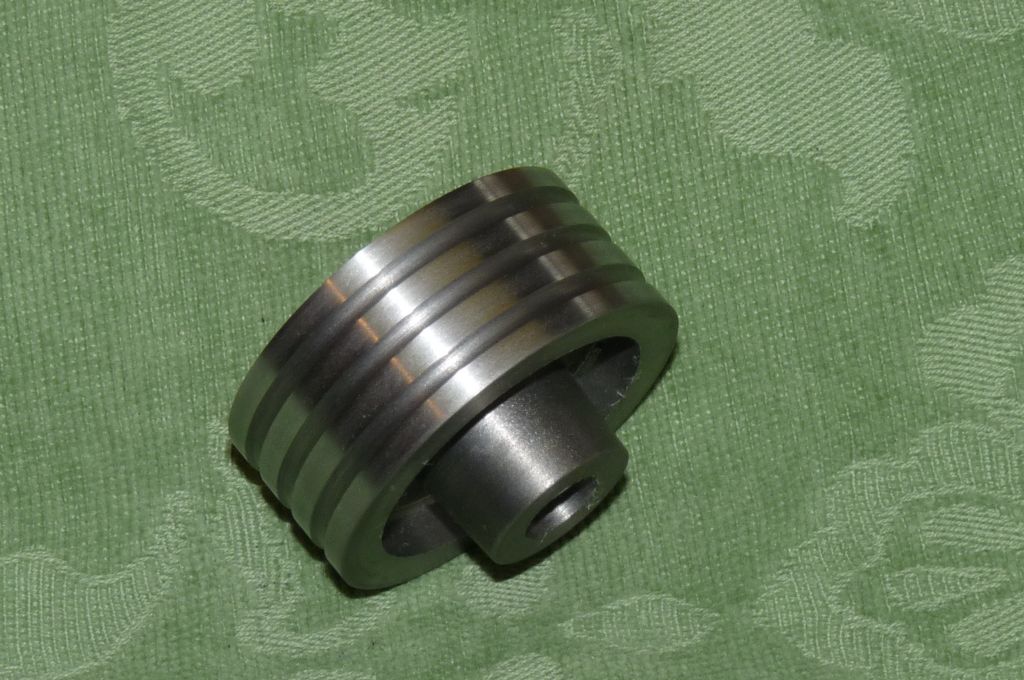
Finally, three grooves have to be cut – the little round nose tool (from 1/8 HSS) is effectively a form tool, so I use the live centre to ensure the cutting forces do not rip my nice pulley out of the chuck and toss it down the shed. Form tools have high cutting forces and here I use very low spindle speeds c100rpm. The tool is not perfectly ground and there is a little bit of chatter in the turned grooves, so I use a 1/8 inch round needle file to tidy up.
And then it's done!
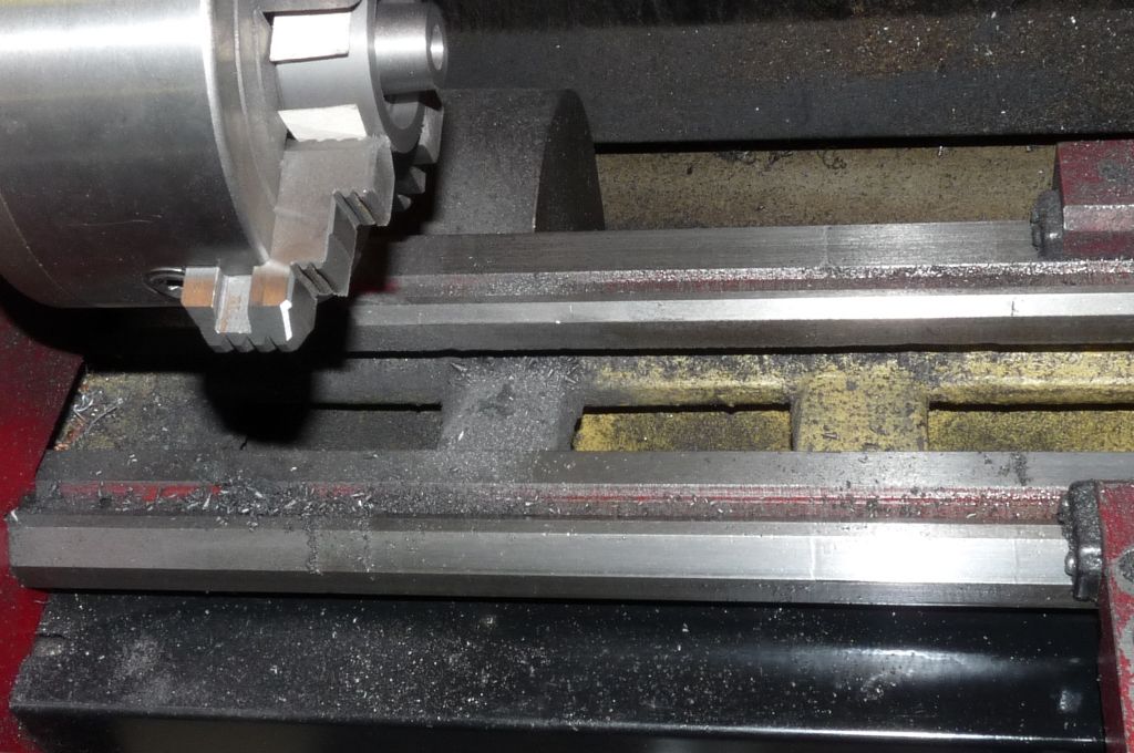
But what a mess this cast iron makes – (This thread is called "with chips"!)
The camera isn't supposed to lie, but the lathe (& me) is a lot dirtier than this in the flesh after completing the pulley.
I'm going to complete all of the cast iron components as a batch as I 'm cheesed off with the mess. I sure the grade of the cast iron used in this kit is different to that in the Victoria I built, I just don't remember those castings being as dirty as these.
Next installment, the flywheel.
Steve
8 June 2014 at 16:03 #154777 Neil WyattModerator@neilwyatt
I wouldn't complain, it probably means more free graphite and therefore freer machining and better wearing.
Neil
8 June 2014 at 16:41 #154782 JasonBModerator@jasonb
Or your tools want a sharpen, those "chips" look quite dusty rather than cleanly cut chips like these. You are rubbing/scraping the metal away rather than cutting it.


Edited By JasonB on 08/06/2014 16:47:40
Edited By JasonB on 08/06/2014 16:48:17
8 June 2014 at 16:54 #154785Steve Withnell
Participant@stevewithnell34426The tools I used for the pulley were ground for the job, so freshly sharp – I wonder if the tool was set too high, so causing the rubbing? There was plenty of dusty stuff!
14 June 2014 at 17:35 #155302Steve Withnell
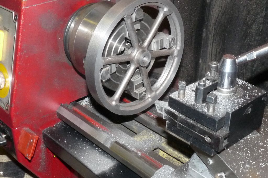
Participant@stevewithnell34426Next component is to machine the flywheel. The flywheel for the James Coombes is 7 inch diameter after machining. It will not go on the face plate as it's just a bit too small to make use of the slots and mount it on the spokes.
I've never made or used mandrels and didn't fancy using a mandrel for this flywheel, the hub is 1 inch wide and I wasn't sure how a mandrel would grip over that length.
So this is the option I chose – though I'm not comfortable with it either:
The forces from the chuck jaws are exactly right for bursting the wheel, so it was trying to make sure that the flywheel was tight enough to avoid any slipping without breaking it.
I started off by drilling and boring the hub to size then facing the rim and outer edge. The flywheel is located by trying to get the unmachined edge to run as concentrically as possible with the centre. Also any wobble needs to be adjusted out.
Once that's all done, the the wheel is turned over, clocked true off the machined hole through the hub, wobble again dialled out so the flywheel is running true and then the edges of the rim and hub are faced to size.
Pretty straightforward. What I didn't do was clean up the outer of the hub, I spotted that Jason had used a button tool to do that. Seems to be a neat trick so will probably follow suit.
Steve
Edited By Steve Withnell on 14/06/2014 17:37:28
15 June 2014 at 09:38 #155340Steve Withnell
Participant@stevewithnell34426Next casting to machine is the cylinder end cap, that also provides a platform for the cross head guides, so it's a bit different to the usual.
I've mounted the casting in the 4 Jaw chuck, with a "circular parallel" to keep it as square as possible, I know some people like to use old ball races for supporting thin workpieces.
In this photo, I'm machining the spigot side first:
The approach I took was to take a light facing cut to clean up the casting. The I turned the spigot diameter to a good fit with the cylinder. Once that was done, I reduced the spigot to the 1/16 depth as per plan. Finally I used a "V" tool to get rid of the little fillet that was left in the corner between spigot and plate.
Next job is to drill and ream a hole for the piston rod –
That all progressed with no issue, so next job is to flip the cylinder cap over and machine the other side. To set up the cap, I used the tailstock to press the plate flate against the "circular parallel" and then clocked it true using the reamed hole as the datum:
Again, skimming the plate just enough to clean it up (the plate thickness has no dimension on the plan) then skimming the gland part of the casting to size all that is left is to counterbore the gland to 5/16.
In this picture, you can see I have added a DRO to the tailstock. This arrangement often fouls the toolpost when working between centres or with tailstock support, so it has to be removed.
Finally, the finished (bar the various mounting holes!) part:
Next piece is the steam chest and cover. I'm sticking to plan of getting all the cast iron machining out of the way, so I'll only have one big clean up to do. The I'll finish all the bits requiring the 4-jaw, such as the eccentrics and bearing mounts.
15 June 2014 at 11:56 #155357Steve Withnell
Participant@stevewithnell34426The steam chest cover is a little casting, just over 4mm thick, which needs to be skimmed both sides to end with a thickness of 1/8. Time for my secret weapon

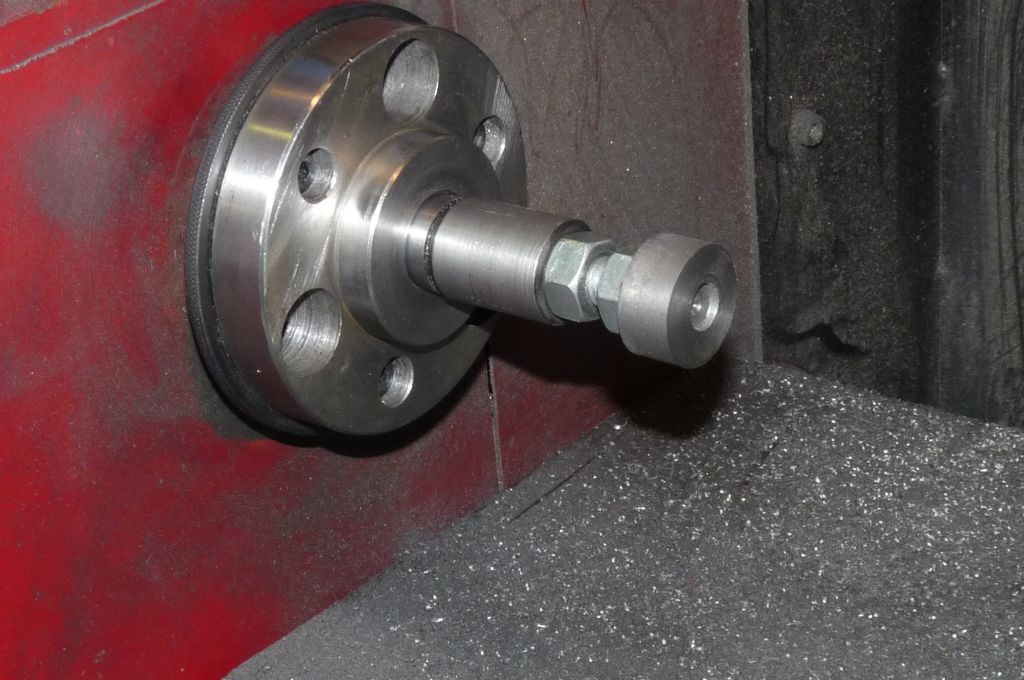
All this is, is a 3MT blank arbor, turned down so it will fit in the centre hole of my 4-jaw chuck. Then it's drilled and tapped to take a piece of 12mm threaded rod (the cheap stuff from the DIY shops). A couple of locking nuts and a piece of sacrificial cast iron and you have an adjustable back stop for help with machining thin materials.
(My technique for facing even thinner materials is to put a piece of cast iron bar in the chuck, face that off and loctite the workpiece to the bar, using the tailstock to hold it in place whilst the Loctite cures. Once the machining is done, warm up with a blow lamp and the Loctite gives up. Good for thinning washers and shims.)
I'll use this backstop for machining the eccentric strap and maybe the bearing blocks.
Slip the four jaw chuck over the top, skim the back stop to ensure it is square against the lathe axes and then mount the steam chest cover:
Taking a cut from both sides to clean up and end up with a nice parallel plate for the steam chest. One thing to be careful of, is that it is a casting so has tapered sides ('draft' I think?). If all the material is taken from the bottom, then the casting might be a bit small to nicely cover the steam chest, so best to take as little off the bottom as possible and all the rest from the top.
Steve
-
AuthorPosts
- Please log in to reply to this topic. Registering is free and easy using the links on the menu at the top of this page.
Latest Replies
Home › Forums › Work In Progress and completed items › Topics
-
- Topic
- Voices
- Posts
- Last Post
-
-
“swedish iron”
Started by:
moonman in: Materials
- 2
- 2
-
12 July 2025 at 03:42
 Fulmen
-
TurboCAD – Alibre File Transfers.
Started by:
Nigel Graham 2 in: CAD – Technical drawing & design
- 1
- 1
-
12 July 2025 at 00:00
Nigel Graham 2
-
Another Day … Another ScumBag
Started by:
 Michael Gilligan
in: The Tea Room
- 11
- 17
-
11 July 2025 at 23:05
 Windy
Windy
-
Sat nag
1
2
Started by:
duncan webster 1 in: The Tea Room
- 14
- 27
-
11 July 2025 at 22:58
Nigel Graham 2
-
buying machine tools from aliexpress experiences?
Started by:
Jake Middleton-Metcalfe in: Manual machine tools
- 14
- 17
-
11 July 2025 at 22:26
Versaboss
-
Adjustable spanner thread direction
Started by:
 jimmy b
in: Workshop Tools and Tooling
- 8
- 8
-
11 July 2025 at 22:14
Nimble
-
Chester Champion, warco ZX15 drawbar
Started by:
martian in: Manual machine tools
- 5
- 7
-
11 July 2025 at 21:51
Howard Lewis
-
Bosch PBD 40 bearing upgrade
Started by:
th1980 in: Manual machine tools
- 6
- 12
-
11 July 2025 at 21:33
Howard Lewis
-
Square end on round stock – Milling?
1
2
Started by:
Roger TheShrubber in: Workshop Tools and Tooling
- 17
- 30
-
11 July 2025 at 21:23
Howard Lewis
-
motor and switch wiring Myford ML7
Started by:
1957jmh in: Workshop Tools and Tooling
- 4
- 6
-
11 July 2025 at 21:09
Howard Lewis
-
I’m Under Pressure
1
2
Started by:
howardb in: Related Hobbies including Vehicle Restoration
- 16
- 30
-
11 July 2025 at 19:12
Nealeb
-
Farm Boy
1
2
…
4
5
Started by:
Dalboy in: I/C Engines
- 15
- 102
-
11 July 2025 at 18:48
Diogenes
-
Sanjay’s Banjo Engine
Started by:
 JasonB
in: Stationary engines
- 3
- 9
-
11 July 2025 at 17:32
renardiere7
-
Old plastic handled screwdrivers
Started by:
 Dave Halford
in: Workshop Tools and Tooling
- 12
- 14
-
11 July 2025 at 17:14
 Robert Atkinson 2
-
Bridgeport ways and wear
Started by:
inline in: Manual machine tools
- 7
- 18
-
11 July 2025 at 09:16
Ian Owen NZ
-
Maisie lubricator
Started by:
ferroequinologist in: Locomotives
- 9
- 14
-
11 July 2025 at 09:09
Clive Foster
-
Transwave converter – plugged in motor, tripped RCD
Started by:
ell81 in: Beginners questions
- 8
- 12
-
10 July 2025 at 22:56
Master of none
-
Eight Trains
Started by:
 Vic
in: The Tea Room
- 1
- 1
-
10 July 2025 at 14:14
 Vic
Vic
-
Help Wire 3 Phase 2 Speed Motor
Started by:
Allan Day in: Electronics in the Workshop
- 13
- 23
-
10 July 2025 at 11:57
Andrew Skinner
-
Easiest/cheapest source of R8 socket
Started by:
Beardy Mike in: Workshop Tools and Tooling
- 8
- 10
-
10 July 2025 at 10:16
Pete
-
New (but well aged) member
Started by:
mikemunson in: Introduce Yourself – New members start here!
- 6
- 6
-
10 July 2025 at 09:23
 Dell
Dell
-
Bearing boxes for ball race
Started by:
Paul McDonough in: Beginners questions
- 11
- 20
-
9 July 2025 at 20:38
old mart
-
Twin Engineering’s heavy mill/drill quill removal
1
2
Started by:
Martin of Wick in: Manual machine tools
- 11
- 34
-
9 July 2025 at 19:42
old mart
-
File backup to external hard drive, incremental etc?
Started by:
Peter Bell in: The Tea Room
- 11
- 17
-
9 July 2025 at 13:50
 Graham Stoppani
-
Boiler Design – issue 4765
1
2
…
7
8
Started by:
Charles Lamont in: Model Engineer & Workshop
- 26
- 186
-
9 July 2025 at 12:28
Paul Kemp
-
“swedish iron”
-
Latest Issue
Newsletter Sign-up
Latest Replies
- “swedish iron”
- TurboCAD – Alibre File Transfers.
- Another Day … Another ScumBag
- Sat nag
- buying machine tools from aliexpress experiences?
- Adjustable spanner thread direction
- Chester Champion, warco ZX15 drawbar
- Bosch PBD 40 bearing upgrade
- Square end on round stock – Milling?
- motor and switch wiring Myford ML7


