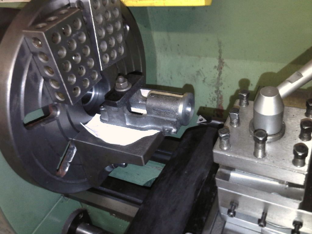
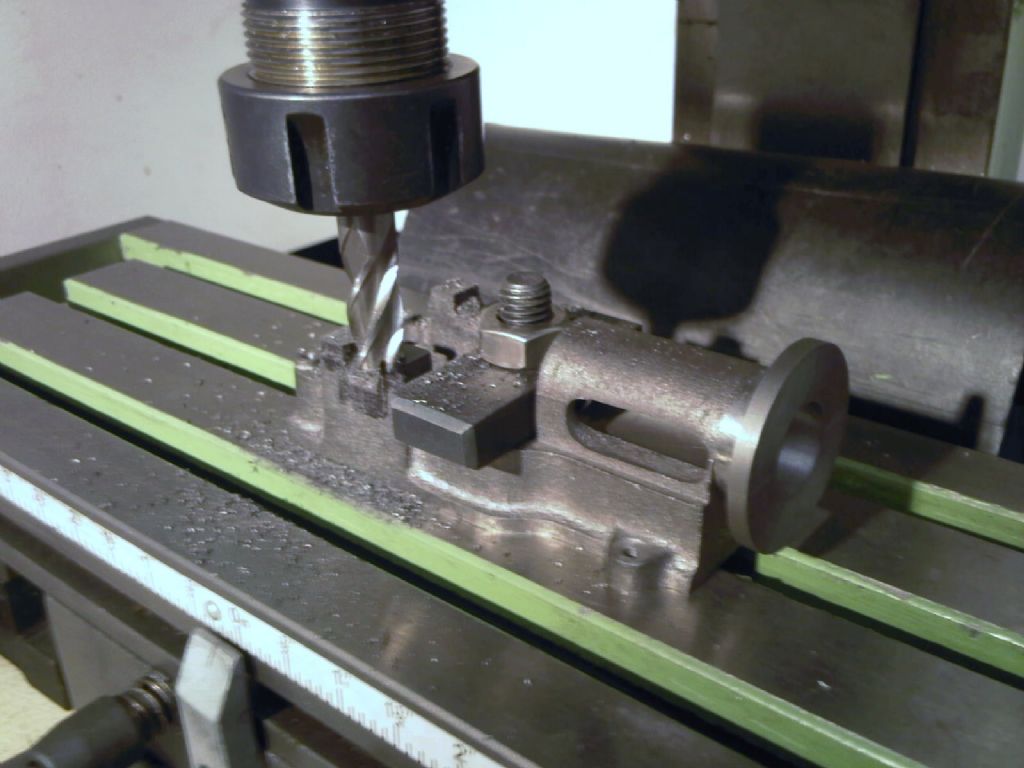
Ian I just find it a lot easier to collect up one lump of heavy sludge, rather htan chase chippings all over the machine.
David – I’m surprised that mill in the picture isn’t rigid enough. Unless its a round column and all the vertical movement required is outside the range of the quill.
There are a number of good reasons to do it on the mill/cross slide. First of course you get a datum across the front using the easily accessible cylinder mounting flanges. Also of course you get another datum – the bed of the mounting plate. That’s parallel to the bores too – automatically. And there is no resetting between bores, other than moving the handwheels. And of course with no second set up, its a lot quicker – without mucking about with angle plates and balance weights.
I;m sure that Tubal Cains “how to guide” will have been extremely good. His stuff always was amongst the best IMO. But I doubt that, when he was writing, the average modeller had access to decent sized mills, in the way that many of us do now.
Yes, of course the faceplate system will work, and with care will work well, despite “2 set-ups”, but not trying to line up off a reamer – used turn and turn about in independent and independently lumpy bores. Much wiser IMO, to have used a square off the faceplate and used the same face or edge on the bedplate as a datum for each set up.
To me, the easiest way to have done the job would have been as follows.
1. M/c the bottom of the bedplate. just skim flat.
2. Set up on a angle plate and done front flanges and bores all at the same setting. If you have a DRO I’d have done the flange bolt holes too.
3. Clamped the bed plate, using the flanges as a datum for square and length, and run a cutter across to do the main bearing channels, – set to depth and height.
4. At the same setting, drilled the bearing stud holes.
5. Finally, if I had no DRO, I’d have machined a spigot, popped it in the bores in turn and done the flange bolt holes on a direct indexer .
6. Then using the spigot, set a 4 jaw to ensure concentricity, I’d have machined the cylinder cover locating spigot on the flange. If its a counterbore, even easier – put it in with a slot drill of the right side plunge cutting at stage2.
Gawd – can you imagine, setting up an angle plate on the face plate, tapping all to get ti in the right place, and at right angles to a notional diamenter line, so you can slide the bed sideways and still maintain height accurately. Then you have to clamp the bed to the plate and get it square, and slide it sideways and do it again for the second bore .
Whichever way you choose, I hope it comes out right.
Nigel McBurney 1.


