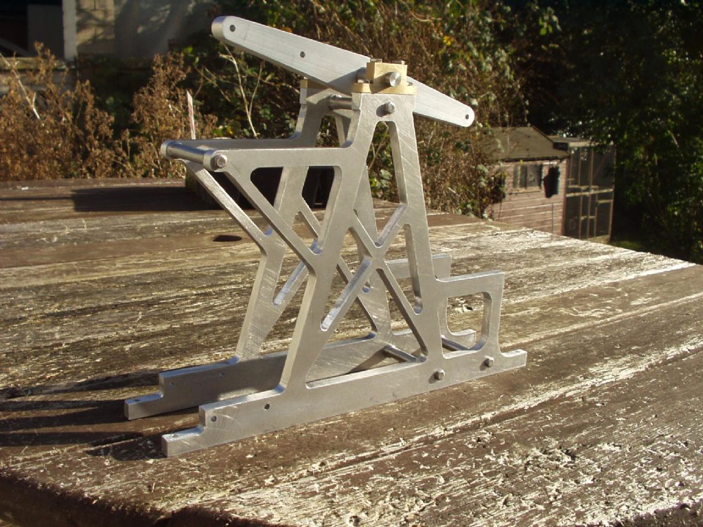
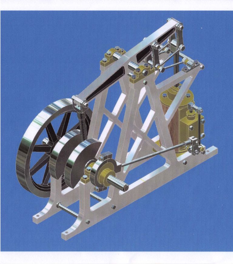
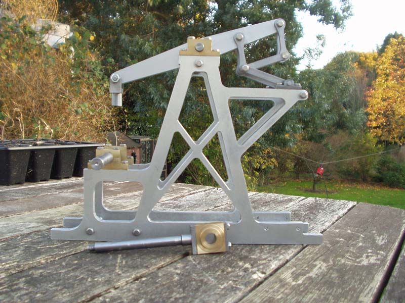
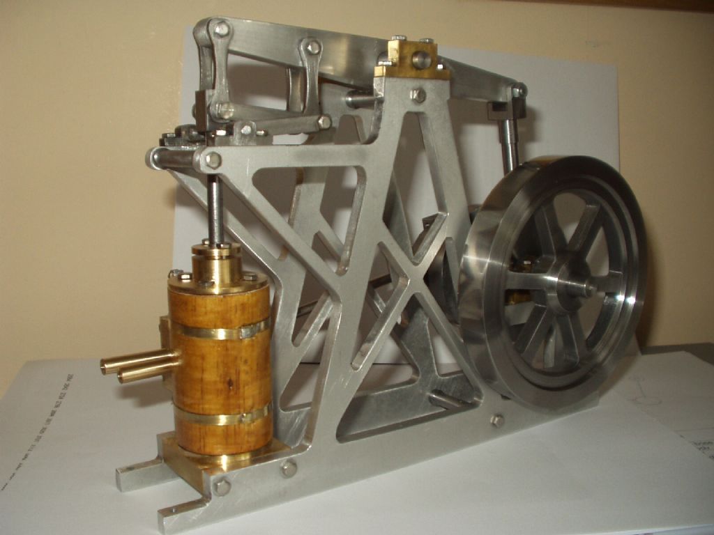
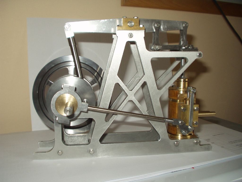
here’s a pic of my new project, I found the plans on the internet and thought it looked different .
the first pic is progress so far
and this is what it should turn out like
the frame is 6mm aluminium, I scaled it up 50% because it looked too much like watchmaking so the flywheel is 4.5 ins , length is 9 ins and height is 7 ins.
I,ll show more as I go but it’s too dam’ cold to do much at the moment.
Patrick, I printed the frame plan full size, bolted the two frames together through two of the waste parts, stuck the plan on with double sided tape then drilled, sawed and filed to the lines.
apart from the base, which was milled square, and the bearing surfaces , which were also milled square to the base.
just the job to keep you warm in an unheated garage/workshop
Circlip, thanks for putting up the link, I assume you’ve seen this before?
just a warning, the plans have a page missing, it appears to have the bearings for the beam, crankshaft and the conrod big end.
however, these are easily gauged from the rest of the plans if they are blown up full size.
I can’t help thinking unpainted models often look better than painted ones. My wife won’t even trust me to paint the skirting board, so my models end up as beautiful engineering hiding inside a sahpeless but colourful blob…
You’ve inspired me to make this beam engine too, I’ve got the plans, including the missing pages ~ did you have any problems? I’m hoping to make the side frames from 6mm brass sheet/plate, unless i can pick some up from the local scrappy