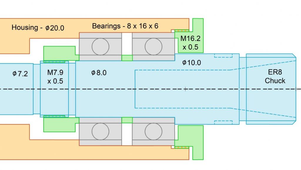
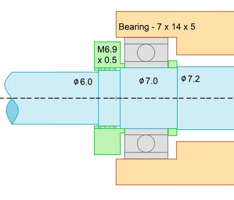
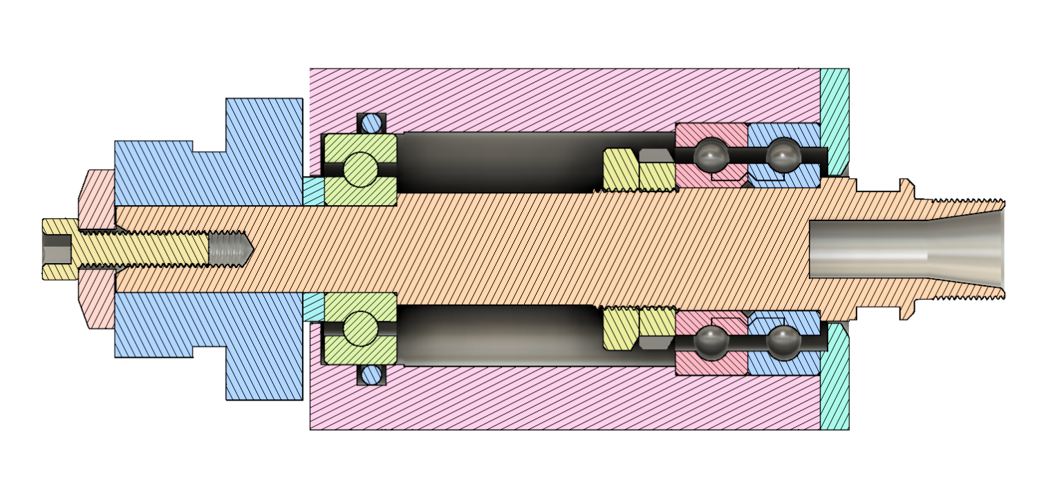
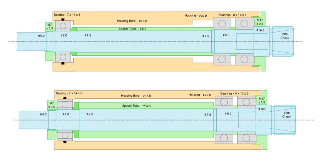
As Howardt says, there's much to be found from bearing manufacturers, available online.
Beware Harprit Sandhu's book. His double taper roller bearing design is OK. All the others are, in my opinion, seriously flawed. Working from memory, most are designed with the outer races abutting shoulders in the housing, and the inner races separated by a spacer tube over the shaft. This is fine, provided you can machine the relevant axial abutment dimensions accurately, but it makes the design non-adjustable, for fine-tuning of axial preload. It should be obvious that this is important when using angular-contact bearings, but it's also important when deep-groove bearings are used. I think there are some designs where axial location must rely on friction fits or adhesive. look critically, before cutting metal!
The axial location of a spindle, and the axial stiffness of its bearings, is clearly of great importance. It's theoretically better for this to be taken care of by a pair of opposed bearings that are close together. If they are at either end of the spindle, its thermal expansion will alter the desired axial pre-load. Probably not a major problem for home machinists' spindles. If the bearing pair is at the 'business end', then you have two bearings sharing radial loads. Thus, designs tend to place bearing pairs at this end. In this case, the bearing at t'other end must be allowed to float axially.
You can get matched pairs of bearings, to be fitted back-to-back, which take care of the axial requirements, but you'll have a limited choice and need deep pockets.
Perhaps the easiest design is with a deep-groove bearing at each end, with the tail-end one spring-loaded in the direction of thrust. This is the headstock arrangement loved by Emco, in its small lathes, and works well, but is, of course, only axially stiff in one direction.
Be aware that there are different grades of bearing available (not counting junk from the East), and beware of the drag caused by rubber seals.
Steve Crow.


