Allchin 1.1.2″ boiler

Advert

Allchin 1.1.2″ boiler

Home Forums Traction engines Allchin 1.1.2″ boiler

Viewing 10 posts - 1 through 10 (of 10 total)
  • Author
    Posts
  • #2927
    Bob Worsley
    Participant
      @bobworsley31976

      Questions on the centre join in the barrel

      Advert
      #436202
      Bob Worsley
      Participant
        @bobworsley31976

        The Allchin barrel is made from a short piece of tube joined to a wrapped sheet that goes over the firebox. Figure 2.1 in the book shows the join between these two pieces. What I don't understand is that the throatplate just touches the underside of the barrel and is soldered there. There is no folded flange going inside the barrel to make a decent area to solder. The drawing just shows a line join between the throatplate and barrel.

        I have done a search of the forum and can find no mention of this.

        The figure 2.1 also shows the waisting of the firebox wrapper which is far more than the 1/32" on the drawing.

        As far as I can see the throatplate needs flanging on the sides backwards into the firebox and forwards into the barrel. This makes for an interesting shape to the copper where the backwards flange meets up with the forwards flange. Must be possible, I imagine all loco type boilers have this double bend at this point, but can't find a photo of one in my limited collection of books.

        The point is that at two points one either side, there seems to be a pinhole gap in the flange where it touches the wrapper and barrel. It also seems to be impossible to reinforce this point with some copper.

        This raises the question that is 13SWG copper sufficiently strong that if this pin hole leaks then the copper has sufficient strength not to tear and cause the boiler to fail? I can find no intelligible information about how strong copper is in tension. If you had the 100PSI steam in the boiler and drilled a hole in the shell, would the steam just rush out or would the boiler explode? Is the tensile strength of the copper greater than the tearing force from the steam? What size hole would there have to be before the steam exceeded the strength of the copper?

        Why wasn't the boiler made with the barrel split and folded down? But this also raises the question that the sides would need to be extended by a small amount. Instructions for other boilers say to rivet these extensions then solder. But again there are now four places where this strap butts up against the flanges at the front throatplate and rear backhead. Is this another source of weakness?

        Reading scientific how to books (Materials and Techniques for Electron Tubes by Kohl) where they use silver soldering and the gap between the two pieces is given as 0.0015" to 0.010" (p382). This is not very much after walloping the copper to flange it. Ok, can clean up the front tube plate on a lathe, but all the others are just filed, 0.010" is a scratch. The scientific book specifically mentions solder dams where it can't flow past a scratch in the joint.

        For example the wrapper side extension pieces. Do you put some flux in the between the side pieces and the reinforcing strap before riveting. Then what happens when it is heated up, has the flux dried? Is it hard and holding the pieces apart? Is assuming the flux will get inside the joint by placing on and around good enough? How do you know any solder has actually gone inside the joint? Don't forget we are looking at just 0.010" gap here.

        The join between the barrel wrapper is made with a piece of 5/8" strip copper, this is 5/16" on each surface. Where is there any figures for the shear strength of copper and soldered joints that this is adequate. With the stresses on this joint from the model moving then this is needed? The steam pressure on this joint at 100PSI is 1104 pounds, or nearly 1000psi tensile.

        Does this need to be addressed? Is is a problem? Tilting at windmills?

        #436214
        Nick Clarke 3
        Participant
          @nickclarke3
          Posted by Bob Worsley on 06/11/2019 11:37:47:

          As far as I can see the throatplate needs flanging on the sides backwards into the firebox and forwards into the barrel. This makes for an interesting shape to the copper where the backwards flange meets up with the forwards flange. Must be possible, I imagine all loco type boilers have this double bend at this point, but can't find a photo of one in my limited collection of books.

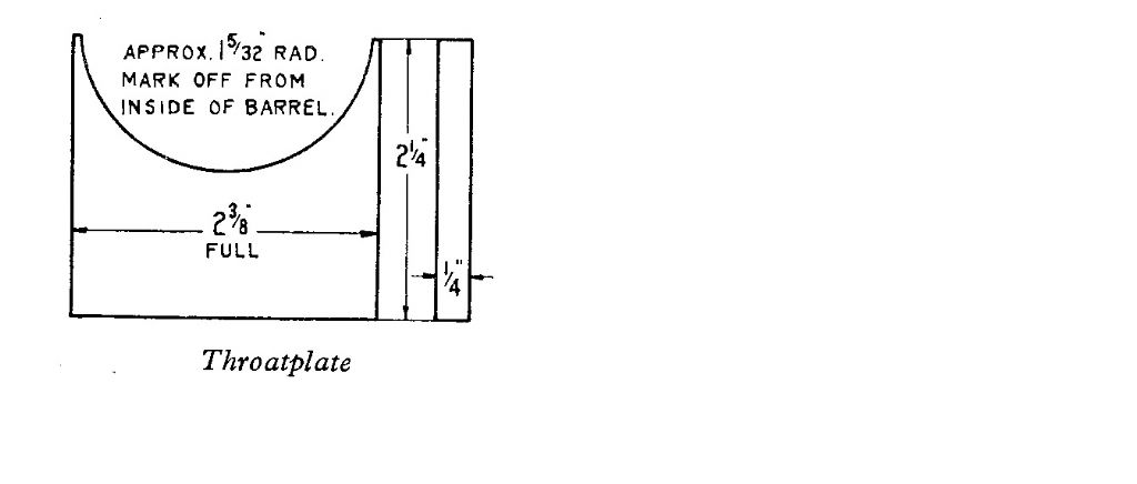
          Not necessarily. This is the drawing of LBSC's Tich loco throatplate, although admittedly some boiler designs do have the 'forwards and backwards' flanges you describe.

          tich throatplate.jpg

          #436215
          JasonB
          Moderator
            @jasonb

            The first line on the "silver soldering" section on page 15 gives a clue. "If you have the necessary heat, then these joints can be BRAZED………"

            Would have been sifbronze brazed back in the day and still acceptable under certain codes. which gives a good strong fillet to the butt joint, there is no forward flange.

            The drawing shows what looks like an 1/8" x 1/8" strip placed into the internal corner formed by barrel and throutplate which will give  alarger area for silver solder to form a strong joint.

            As with all things boiler related talk to your boiler inspector to see what he will find acceptable, you may be able to use a grade of Silver solder that forms a good fillet or he may want some sort of flange.

            Edited By JasonB on 06/11/2019 13:04:58

            #436233
            John Baguley
            Participant
              @johnbaguley78655

              As Jason suggests, there is a 1/8" square reinforcing strip in the corner of the joint which increases the surface area of the joint. That's how I built mine years ago. That should still be acceptable nowadays and is a lot easier than making a double flanged throatplate.

              I doubt if a plain butt joint as shown by LBSC for Tich etc.would be considered acceptable practice now in the UK although, as Jason says, talk to the boiler inspector.

              John

              #436238
              Nick Clarke 3
              Participant
                @nickclarke3

                It is an interesting position to be in – we know nowadays that there are better ways of doing things, but if we do things differently to the design drawings when does it become a different design and calculations etc need to be produced?

                Just curious!

                #436249
                Former Member
                Participant
                  @formermember19781

                  [This posting has been removed]

                  #436308
                  Bob Worsley
                  Participant
                    @bobworsley31976

                    No!

                    Do not confuse brazing with braze welding, or bronze welding.

                    Brazing uses what is in effect a piece of brass to join the parts, and it also requires a few thou gap for the spelter to run in by capillary action. Braze welding uses a different type of filler that will only form a fillet.

                    Added to that the throatplate joint will be made after other joints, tubes etc, so they also would need to be braze welded due to the far higher temperature this requires.

                    No one has picked up on my point about pinholes and the possibility of them opening up under steam pressure.

                    If the method of construction requires a change, then what is wrong with that? I would plan to use metric threads rather than inch, another change.

                    If you read the Haining book about boilers for ploughing engines then he talks about the Greenly method of boiler design, but that is thickness of metal, not that they think a line joint several inches long is good enough for 100psi.

                    #436317
                    JasonB
                    Moderator
                      @jasonb

                      No confusing here.

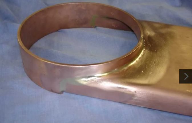
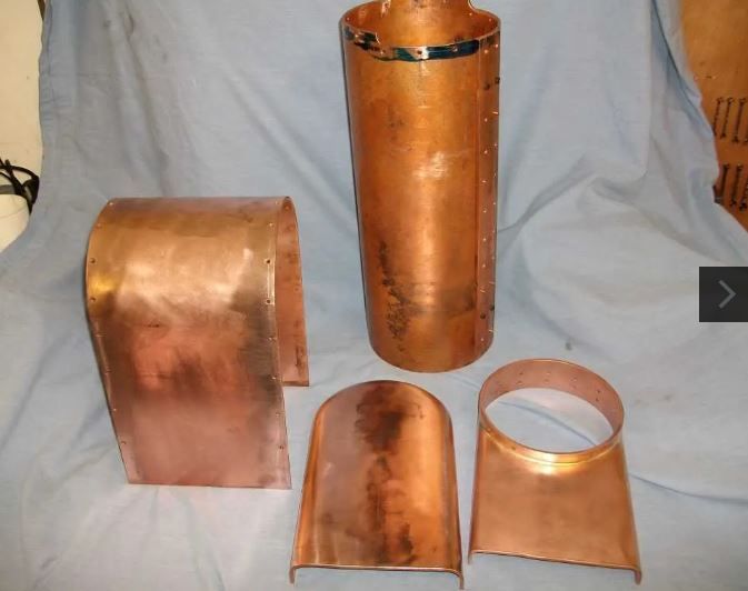
                      Th throatplate and ring can be made up as one and brazed so no problem with the higher temps affecting anything else so Brazing is OK , much like this one for a Fowler

                      dougs throatplate 1.jpg

                      dougs throatplate 2.jpg

                      dougs throatplate 3.jpg

                      You can then pop a couple of loose rivits or bronze screws in to the ring to hold it to the barrel while the joint is silver soldered, ditto the wrapper. The lower half of the barrel will need some tidy fitting to get a minimal gap where it joins the throatplate.

                      Which should allow for a good solder joint

                      Nothing wrong with changes to construction provided boiler inspector is happy with them though having seen the copper strip after I posted about brazing I can't see any need to deviate from the strip method.

                      #436354
                      Bob Worsley
                      Participant
                        @bobworsley31976

                        That is exactly it. Perhaps it is time the drawings were updated to reflect modern construction methods?

                      Viewing 10 posts - 1 through 10 (of 10 total)
                      • Please log in to reply to this topic. Registering is free and easy using the links on the menu at the top of this page.

                      Advert

                      Latest Replies

                      Home Forums Traction engines Topics

                      Viewing 25 topics - 1 through 25 (of 25 total)
                      Viewing 25 topics - 1 through 25 (of 25 total)

                      View full reply list.

                      Advert

                      Newsletter Sign-up