VFD size

Advert

VFD size

Home Forums General Questions VFD size

Viewing 25 posts - 1 through 25 (of 29 total)
  • Author
    Posts
  • #28425
    colin hamilton
    Participant
      @colinhamilton16803
      Advert
      #570031
      colin hamilton
      Participant
        @colinhamilton16803

        I'm running a 3hp 3 phase lathe via a VFD. I matched the VFD to the motor but on reasonable sized cuts 1.8mm off the diameter (on steel) it trips. Is this likely to be one of ghe settings or is it better to oversize the VFD?

        #570035
        Mike Poole
        Participant
          @mikepoole82104

          Remember that when you turn the speed down the power available will be less, using the belts or gears to keep the motor running at near its rated speed will maximise the power available. The VFD should have the motor current set to the full load current of the motor. Does the VFD error indicate an over current trip?

          Mike

          #570050
          Zan
          Participant
            @zan

            It also depends on the quality of the vdf. A decent one will compensate for the loss of power/torque to the limit of the power setting mentioned above. Avoid cheap vdf units!

            #570057
            colin hamilton
            Participant
              @colinhamilton16803

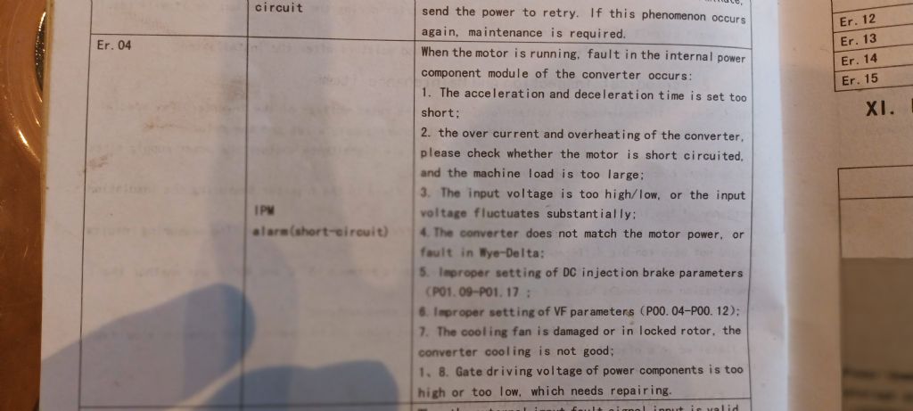
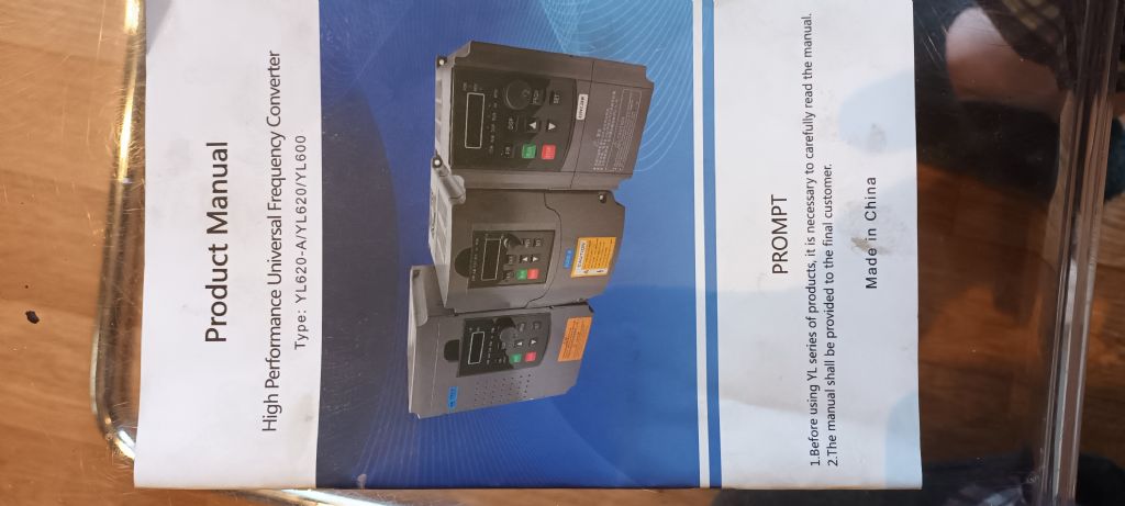
              I have a chipmaster so I vary the speed via a mechanical variator and it has a clutch so the vfd runs the motor at a constant 50hz. It is tripping on error code 4 which covers a load of sins one of which is over current. I definately bought cheap (you can tell be the manual!!). I am thinking I will simply replace it with something better. That's really the reason for my question will a quality 3hp vfd (3hp motor) be enough or is it still better to somewhat oversize.

              #570060
              DC31k
              Participant
                @dc31k
                Posted by colin hamilton on 06/11/2021 05:44:02:

                It is tripping on error code 4 which covers a load of sins one of which is over current

                Just saying it trips with an overcurrent fault does not tell us much. For the particular setting that is currently programmed into the VFD, 'over current' could be 0.5A.

                As Mike says, the maximum current value is normally a user-settable parameter in the VFD. Read the manual or post a link to it and the VFD here and we can advise further. Try to measure the current the motor is actually pulling: separate one of the phase wires from the others and put a cheap current clamp meter on it.

                Make sure the ingoing supply to the VFD is adequate – cross-sectional area of wires and length of cable, even more so if you decide to pursue your 'somewhat oversize' route.

                Is the output of the VFD wired directly to the motor?

                #570066
                not done it yet
                Participant
                  @notdoneityet

                  Looking at all possibilities (your fault is more likely with the VFD settings or installation) are the motor phase windings equal? An imbalance could lead to tripping. Is the motor a dual voltage machine?

                  A couple of mm depth of cut is not the whole story, by any means. Diameter, rotational speed and feed rate will all affect the power loading – as would the sharpness of the cutter and the material being worked.

                  The VFD may be too small (particularly if cheap chinese) as a 3 HP motor should deliver that power (2.2kW) but will require a greater input power, depending on the motor efficiency.

                  #570069
                  AJAX
                  Participant
                    @ajax

                    I have 4 WEG vfd units and I can't fault them. They are high quality, easy to wire up and include comprehensive user manuals. The price is good too. No need to oversize them.

                    #570071
                    colin hamilton
                    Participant
                      @colinhamilton16803

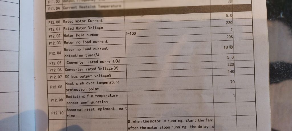
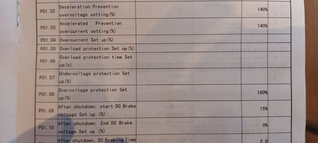
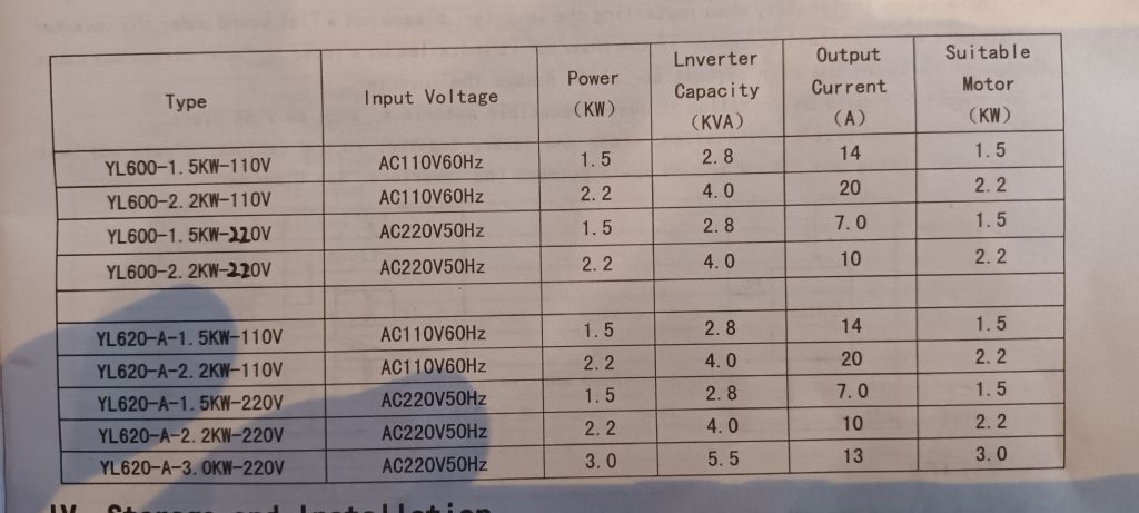
                      img_20211106_081920.jpgimg_20211106_081901.jpgimg_20211106_081754.jpgimg_20211106_081451.jpgI'm happy that the motor is operating OK as best I can. All the insulation resistance was checked on installation. I'm OK with the incoming feed. Its on a stand alone ring (2.5mm twin core and earth) and is no more than 5m from the main box. It all runs fine when I am taking it easy but starts to trip when the tool loading goes up. I do struggle understanding the manual I've copied what I think are the relevant sections below. At the moment the display is set to frequency I think this can be reconfigured to motor current would this be equivalent to actually measuring one of the phases?

                      img_20211106_081402.jpg

                      #570082
                      Steve R
                      Participant
                        @steverichardson2

                        I have a similar set up on my chipmaster and its great.

                        Id seriously be checking some of the basic settings, particularly your motor parameters in the VFD. Maybe I missed it, but what 'kw' is your VFD rated to 2.2kw ? – thats possibly a bit low.

                        And I assume your motor is set up in the connection box to 'delta' – output voltage for the phases to the motor needs to be 230v.

                        I have set up a few of these now and the only time I had problems was when I didn't have some of the basics right. A good manual helps though.

                        #570084
                        Tim Stevens
                        Participant
                          @timstevens64731

                          In the model aeroplane world, there are small devices which turn battery DC into 3-phase, with the frequency varied by a potentiometer. They are used to drive propellers and drone rotors etc.

                          It seems to me that the device concerned must be a very small version of a VFD. Am I correct?

                          The radio controlled versions must (I guess, again) be worked by a digital message – ie an on-off signal like a version of morse code. Is this right? If so, isn't this a close relative of CNC?

                          Regards – Tim

                          #570096
                          Mike Poole
                          Participant
                            @mikepoole82104

                            A typical motor rating plate for a 3 phase motor suitable for use with a single phase input VFD will quote a voltage for star and delta connections and also a full load current (FLC) for both connections. Typical figures for a suitable motor will be voltage in Delta 220v and star 400v, currents for a 2.2kW motor will be around 8A in Delta and 5A in star, The VFD parameters should reflect these figures for your particular motor. I believe the Chipmaster had a two speed motor and these are not usually suitable to run from a VFD. If this is the case then a more suitable motor may be required. A picture of the motor plate would be great but I understand it is probably not very accessible in the machine.

                            Mike

                            #570100
                            Emgee
                            Participant
                              @emgee

                              Colin

                              The motor plate shown in your Album is from a 4 pole (1450rpm) so you need to change that in parameter settings if the plated motor is on your lathe.

                              Emgee

                              #570105
                              Anonymous
                                Posted by Tim Stevens on 06/11/2021 10:03:56:

                                It seems to me that the device concerned must be a very small version of a VFD. Am I correct?

                                Not really, similar hardware but different software and output waveforms.

                                A VFD usually drives an induction motor, which is asynchronous, ie, motor speed is not quite the same as would be expected from the applied frequency. The output waveforms from a VFD are PWM with a carrier frequency in the range of a few kHz to low 10s of kHz. The width of each pulse is different so that the underlying fundamental of the PWM is a sine wave of appropriate frequency (usually low Hz to 400Hz) for the required motor speed.

                                It is assumed that the propellor/drone motors are brushess DC. These are synchronous motors, ie, the motor runs exactly at a speed determined by the frequency of the applied signals. The output signals are a series of pulses, with the repetition rate being that needed for the required motor speed, ie, no PWM.

                                The signals required for a BLDC motor are simpler than for an induction motor, so the control algorithms and software complexity are also simpler.

                                Andrew

                                #570107
                                Anonymous
                                  Posted by Mike Poole on 06/11/2021 11:38:56:

                                  …..a two speed motor and these are not usually suitable to run from a VFD.

                                  I can't see a problem running a 2-speed motor from a VFD, provided only one speed range is used. A potential problem arises if both speed ranges are needed, as one would need to change parameters in the VFD (number of poles and rated current as a minimum) each time the speed range was changed. I have a vague recollection that some VFDs allow multiple parameter sets which are selected via an external switch.

                                  Andrew

                                  #570118
                                  DC31k
                                  Participant
                                    @dc31k
                                    Posted by Andrew Johnston on 06/11/2021 12:16:41:

                                    I can't see a problem running a 2-speed motor from a VFD

                                    The challenge using a 2-speed motor with a VFD is that it is not possible to configure the motor to accept 230v three-phase. You can run either speed of a 2-speed motor off a VFD that outputs 415v three-phase with all the precautions you rightfully highlight.

                                    As I understand it, the most common way for a two-speed motor to be configured is 'Dahlander wound'. If you find diagrams of this configuration (e.g. https://www.wikiwand.com/en/Dahlander_pole_changing_motor), you can see how a standard low voltage delta configuration of the windings is not possible. Very briefly, from the above link, in low speed the motor is wired high voltage delta and for high speed, it is wired double-star.

                                    #570121
                                    Clive Foster
                                    Participant
                                      @clivefoster55965

                                      Concerning the need for parameter changes when using VFD boxes on two speed motors I suspect this isn't really needful unless running close to maximum output or wanting peak efficiency. Maybe more important with self tuning vector drive types if you want to retain the low speed torque boost ability.

                                      Certainly the 10 hp Plug and Play VFD box supplied by Drives Direct that does a very respectable imitation of utility power in my workshop doesn't seem to care whether or not a motor is two speed or what speed its on. It just sits there driving a set of smoothing inductors at 50 hz and the normal machine controls do the rest.

                                      That said my largest motor is 3 hp so its working well within its capabilities and, obviously, I don't use the variable speed abilities.

                                      If Colin's Chipmaster still has its mechanical variable speed device I see no great advantages from using the VFD for variable speed. Hence odds are any sophisticated tuning parameter errors will be of little importance as 50 Hz is 50 Hz and the clever stuff is mostly to improve behaviour at other frequencies for which the motor wasn't explicitly designed.

                                      However, as DC31k posted whilst I was typing, if Colin still has the two speed motor it can't be reconfigured to delta for 220 V input so it needs full fat 420 (nominal) volt 3 phase to work properly. I'm dubious of the ability of the so called "380 volt output" import VFD boxes being able to properly drive a UK 2 speed machine tool motor. The common designs are lovely machines but, for complex design reasons, are inherently notorious current hogs off frequency and during start up.

                                      Clive

                                      Edited By Clive Foster on 06/11/2021 13:08:27

                                      Edited By Clive Foster on 06/11/2021 13:08:49

                                      #570141
                                      colin hamilton
                                      Participant
                                        @colinhamilton16803

                                        I reconfigured the motor to 220v 3phase. I sized the vfd on a simple 3 hp motor is 2.2 kW so I bought a vfd rated at 2.2 kW. I am seriously wondering because I went cheap it's only going to be good for 2.2kw on a good day. My lathe is nearly 50 and driving through a similar aged variator. I think I might just go better quality and a bit bigger say 3.5kw and get a bit spare in the bag.

                                        Can anyone recommend a UK trusted supplier of decent vfd's?

                                        #570152
                                        Harry Wilkes
                                        Participant
                                          @harrywilkes58467

                                          Colin before running out and buying a new VFD check that P12 is set to around 8 amps

                                          H

                                          #570154
                                          Robert Atkinson 2
                                          Participant
                                            @robertatkinson2

                                            What is the actual current setting on the VFD? This is P12.0 (motor) and P12.5 (drive). The tables you show say 5A set but that a 2.2kW VFD output is 10A max.

                                            Robert G8RPI.

                                            #570158
                                            Clive Foster
                                            Participant
                                              @clivefoster55965

                                              Colin

                                              Inverter Drive Supermarket are my go to supplier. Prices are reasonable and they have a well deserved reputation for going that bit further to ensure you get a device suitable for your needs.

                                              When you say reconfigured the motor do you mean that you connected the parallel connected "double Y " windings in delta just as is done with a normal motor with single windings?

                                              I'm told this isn't a good thing to do as it reduces efficiency and raises power consumption. Makes no sense to me as surely a pair of parallel windings is equivalent to a single winding. If it works in Y it ought to work in delta.

                                              However there must be a reason why received wisdom is that you can't do the conversion although all the connections are there.

                                              Clive

                                              #570168
                                              Robert Atkinson 2
                                              Participant
                                                @robertatkinson2
                                                Posted by Clive Foster on 06/11/2021 15:06:21:

                                                Colin

                                                Inverter Drive Supermarket are my go to supplier. Prices are reasonable and they have a well deserved reputation for going that bit further to ensure you get a device suitable for your needs.

                                                When you say reconfigured the motor do you mean that you connected the parallel connected "double Y " windings in delta just as is done with a normal motor with single windings?

                                                I'm told this isn't a good thing to do as it reduces efficiency and raises power consumption. Makes no sense to me as surely a pair of parallel windings is equivalent to a single winding. If it works in Y it ought to work in delta.

                                                However there must be a reason why received wisdom is that you can't do the conversion although all the connections are there.

                                                Clive

                                                From the picture of the motor plate in the OP's album the motor is a conventional single speed 3 phase.

                                                #570171
                                                colin hamilton
                                                Participant
                                                  @colinhamilton16803
                                                  Posted by Clive Foster on 06/11/2021 15:06:21:

                                                  Colin

                                                  Inverter Drive Supermarket are my go to supplier. Prices are reasonable and they have a well deserved reputation for going that bit further to ensure you get a device suitable for your needs.

                                                  When you say reconfigured the motor do you mean that you connected the parallel connected "double Y " windings in delta just as is done with a normal motor with single windings?

                                                  I'm told this isn't a good thing to do as it reduces efficiency and raises power consumption. Makes no sense to me as surely a pair of parallel windings is equivalent to a single winding. If it works in Y it ought to work in delta.

                                                  However there must be a reason why received wisdom is that you can't do the conversion although all the connections are there.

                                                  The motorvonly gas sigle windings. I wascheloedvthrough it by the good people on here. If you search for chipmaster motor windings on here you will see all the detail. The motor plate is marked up for both star and delta so I'm happy that it's appropriate. Thanks for the inverter supplier recommendation

                                                  #570172
                                                  colin hamilton
                                                  Participant
                                                    @colinhamilton16803
                                                    Posted by Emgee on 06/11/2021 11:52:41:

                                                    Colin

                                                    The motor plate shown in your Album is from a 4 pole (1450rpm) so you need to change that in parameter settings if the plated motor is on your lathe.

                                                    Emgee

                                                    Thanks I managed to spot that when I first set it up.

                                                    #570173
                                                    colin hamilton
                                                    Participant
                                                      @colinhamilton16803
                                                      Posted by Mike Poole on 06/11/2021 11:38:56:

                                                      A typical motor rating plate for a 3 phase motor suitable for use with a single phase input VFD will quote a voltage for star and delta connections and also a full load current (FLC) for both connections. Typical figures for a suitable motor will be voltage in Delta 220v and star 400v, currents for a 2.2kW motor will be around 8A in Delta and 5A in star, The VFD parameters should reflect these figures for your particular motor. I believe the Chipmaster had a two speed motor and these are not usually suitable to run from a VFD. If this is the case then a more suitable motor may be required. A picture of the motor plate would be great but I understand it is probably not very accessible in the machine.

                                                      Mike

                                                      It's got single windings. I was helped through reconfiguring it to delta btvghe experts on here. All the details are in one of my earlier post "chipmaster motor windings"

                                                    Viewing 25 posts - 1 through 25 (of 29 total)
                                                    • Please log in to reply to this topic. Registering is free and easy using the links on the menu at the top of this page.

                                                    Advert

                                                    Latest Replies

                                                    Home Forums General Questions Topics

                                                    Viewing 25 topics - 1 through 25 (of 25 total)
                                                    Viewing 25 topics - 1 through 25 (of 25 total)

                                                    View full reply list.

                                                    Advert

                                                    Newsletter Sign-up