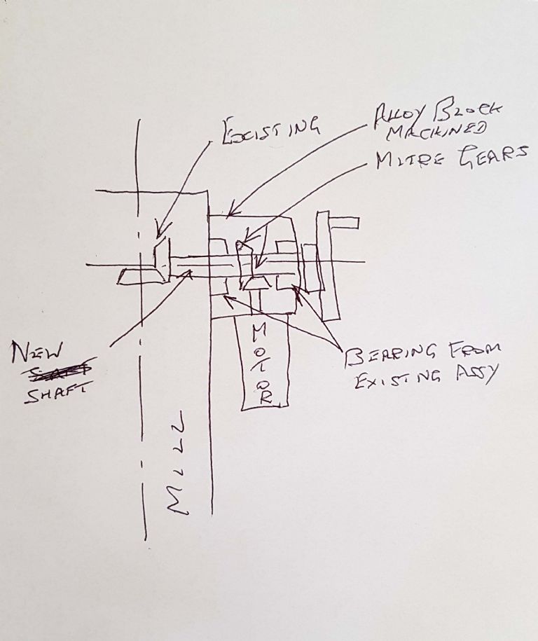
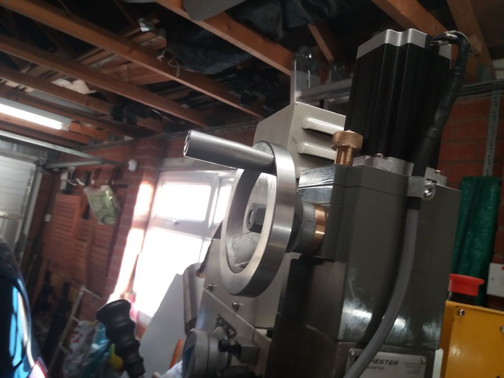
The device shown by Ian P has a vertical lead screw for the Z movement. This is fitted (originally) with a mitre gear and the handle fits in place of the motor drive shown. So, it should be easy to extend the lead screw upwards (perhaps by a more complex nut) and fit a motor there, the motor having internal gearing to reduce its rpm. This would leave the original handle in place, and it would rotate in sympathy with the motor drive.
Of course, you also need a manual drive, without turning the motor. So, you need a dog clutch between the motor and the lead screw.
The motor you need will be geared down a lot to about 50 – 100 rpm, and the torque at the output wuill need to be rather more than the torque required to turn the lead screw nut in normal conditions. The motor is likely to be specified as output torque at the motor (not including reduction gears) and so many rpm. Knowing this the reduction ratio and output torque needed can be calculated fairly simply. Halve the RPM and you nearly double the torque. 10% of the rpm gives you about 80 times the torque. [It would be 100 times if the gearbox did not add a friction load.] And it does no harmn to have a bit of torque in reserve.
Remember that you must include switches to turn off the motor automatically just before the Z movement gets to the end of its travel. Best to do this first, or you might get carried away with your efforts and try switching on before it is finished … And another switch which cuts out the motor as you disconnect the clutch.
The voltage you need is not really a serious concern, but – a low voltage motor is much safer than anything on the mains supply. Just chose from what is on offer, bearing in mind it will need a power supply, so 12V seems favourite perhaps using a computer power box. But it must be a DC motor or you will have fun reversing it.
Hope this helps
Tim
Edited By Tim Stevens on 23/07/2019 15:00:29
Stuart Smith 5.


