11cc Wall

Advert

11cc Wall

Home Forums I/C Engines 11cc Wall

Viewing 24 posts - 1 through 24 (of 24 total)
  • Author
    Posts
  • #590514
    JasonB
    Moderator
      @jasonb

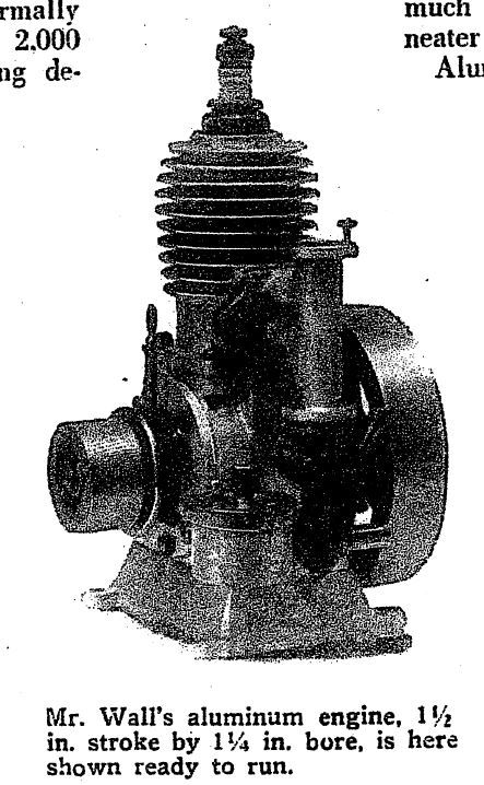
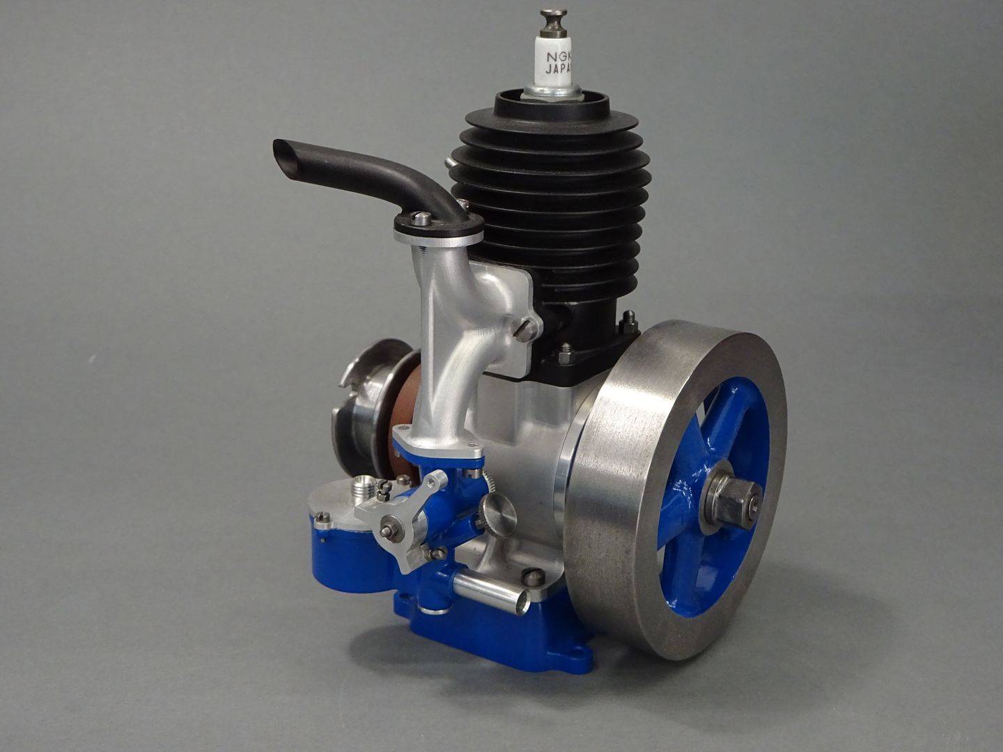
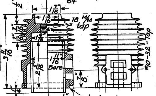
      This engine is based on a design by Elmer Wall that was published in "Model mechanics and Inventions" and despite asking around I have not been able to find an up to date photo of one, the best is a rather grainy image from scans of the original magazine article.

      There was some talk of the old patterns having been bought, reworked and a limited run going to be produced but again I can find no sign of any of these casting sets if they were ever actually done nor mention of the original castings that Wall produced.

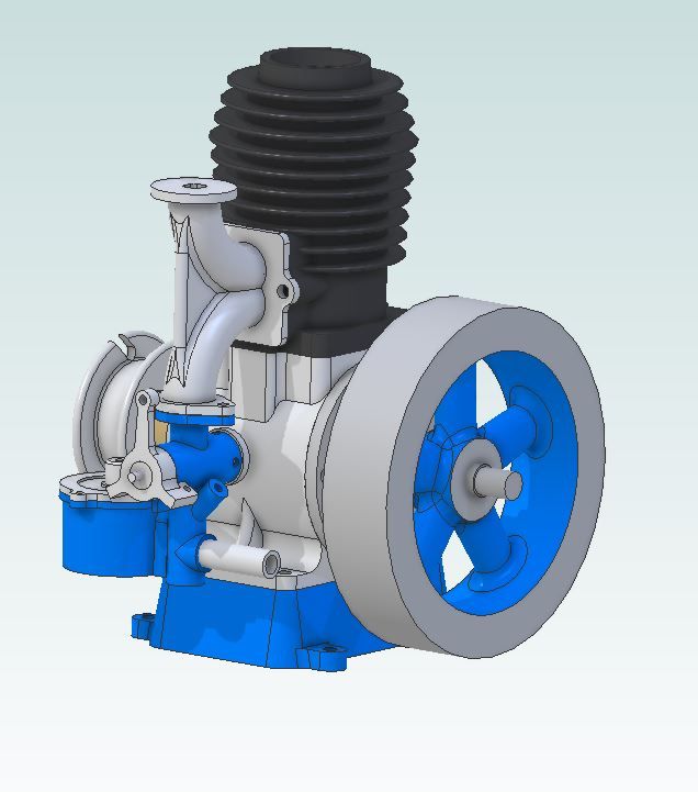
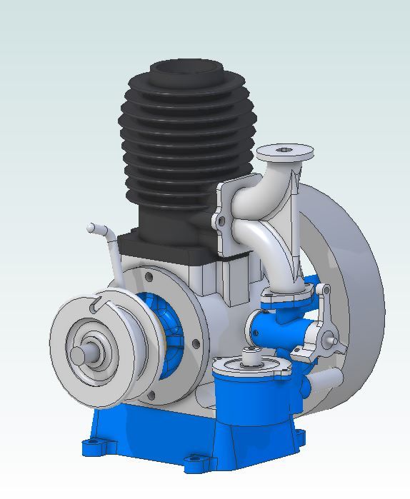
      In redesigning the engine I opted for my usual 24mm bore which makes scaling the imperial sizes down to metric quite straight forward using the ratio of 1/16" on the original = 1mm on my drawings. At this size the original 36cc capacity comes down to 11cc. The parts were all 3D modelled in Alibre and assembled there two which allows for checking that things will fit and rotate rather than find problems during the build. This is something I have taken to doing with all models now as you can sort out legacy errors which saves headaches down the line, it is also a good way to get to think of how you are going to machine the parts.

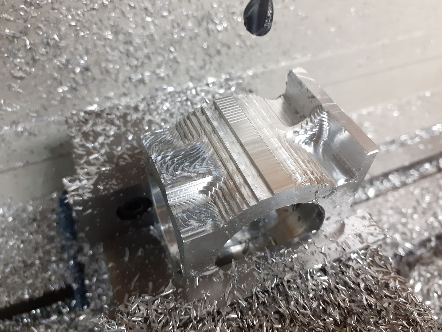
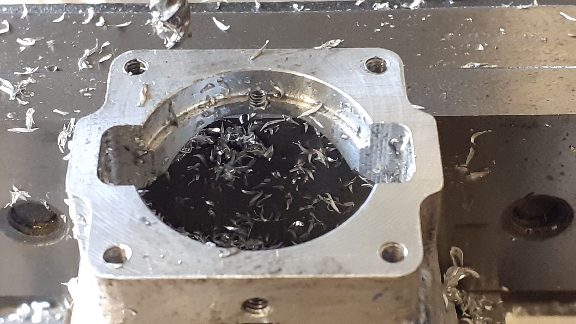
      I decided to make a start with the crankcase which was from a block of 6082. After squaring up the block and marking the crank and cylinder positions it was held in the 4-jaw to bore out to diameter for the end plates and then an HSS tool was used to enlarge the cavity to clear both the crank webs and deeper still in the middle to clear the conrod big end.

      The block was then repositioned to bore the piston clearance and a larger recess to locate the cylinder liner.

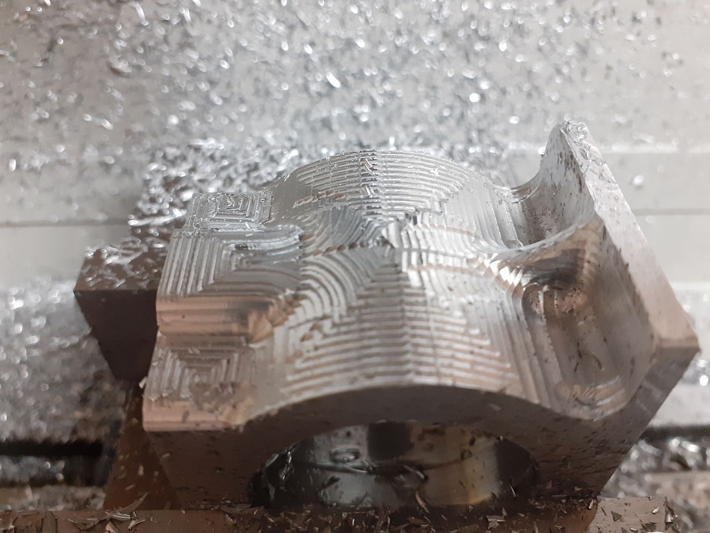
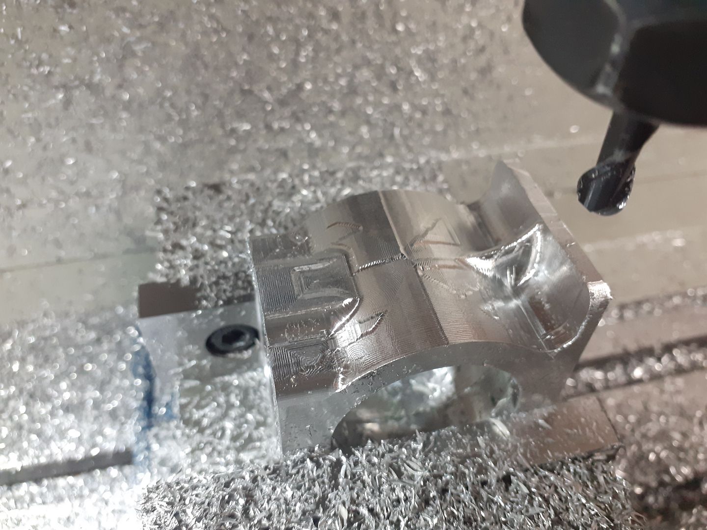
      For the external shaping of the crankcase I decided to make use of the CNC, the following photos show it taking shape after each of the various stages of machining.

      An adaptive clearing path was used first to remove most of the material using a 5mm flat ended 2-flute carbide cutter specifically for aluminium.

      I then changed to a 6mm 2-flute ball ended carbide cutter and did a coarse "steep and shallow" path to remove most of the remaining material but leaving 0.2mm for finishing with a 1mm stepover

      The same tool was then run again with a 0.3mm stepover to get a finer finish

      At the time this was done I had not quite got my Z axis movement smooth so there are a few more steps than there are now but nothing a little needle file work could not sort out.

      I probably showed this video in the CNC section but won't hurt to post again

      Advert
      #2631
      JasonB
      Moderator
        @jasonb
        #590565
        Roderick Jenkins
        Participant
          @roderickjenkins93242

          Great stuff Jason. How did you locate the axes zeros after rotation of the stock to machine each face?

          Cheers,

          Rod

          #590580
          JasonB
          Moderator
            @jasonb

            Nothing super technical Rod. Y-axis was simple enough as I just turned the work 180deg and used the fixed vice jaw as location.

            As there was more metal removed from the top if the case than the bottom I could not just rest it against the bottom of the vice so used a square against the underside of the case (right hand vertical face in images and video). I probably could have clamped a 1-2-3 block to the table and used that as a vertical stop

            Then finally edge finder against the now vertical face to get it lined up in the X-axis, I had used that bottom face as my datum for the CNC so just zeroed Z again.

            It only needed two setups as the ends did not need to be cut on the CNC.

            #590586
            DiogenesII
            Participant
              @diogenesii

              Watching with interest.. yes

              #590611
              Howard Lewis
              Participant
                @howardlewis46836

                proving that Engineer came from the Greek word for ingenious!

                I like the neat method of "scaling" to sizes.

                Very good work Jason!

                Howard

                #591575
                JasonB
                Moderator
                  @jasonb

                  Once the CNC work was done on the crankcase it was then just a case of treating it like any other casting and doing the easy bit of drilling and tapping the various holes and also milling a couple of clearance notches at the sides of where the cylinder mounts to allow the transfer of the air/fuel mix.

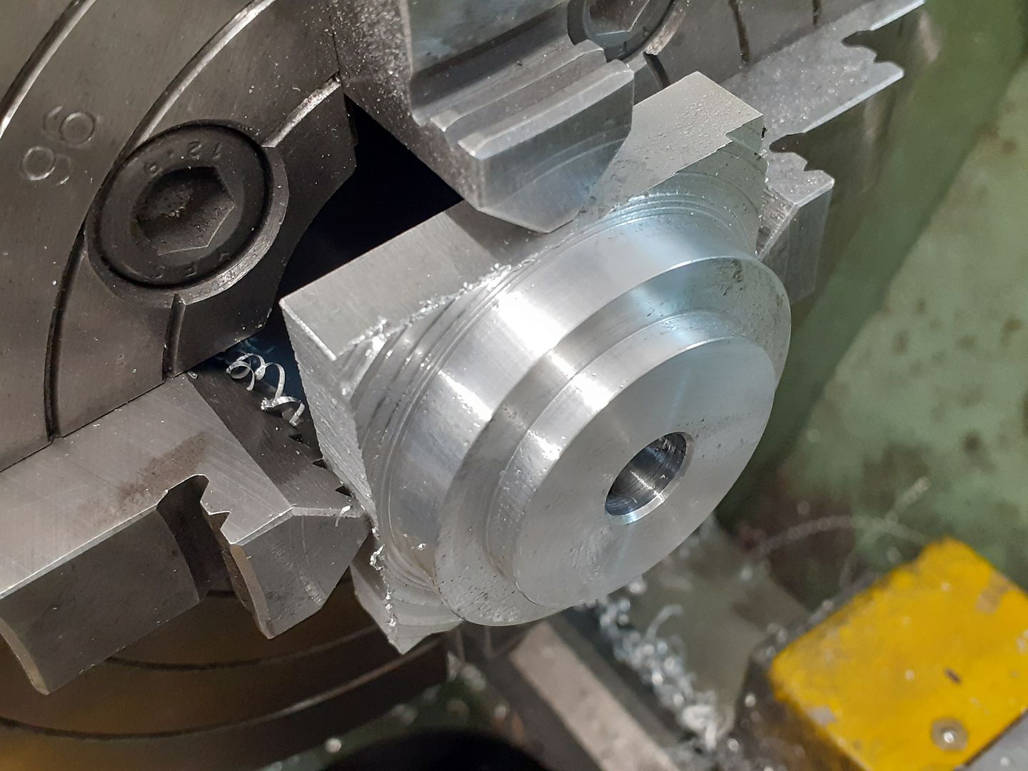
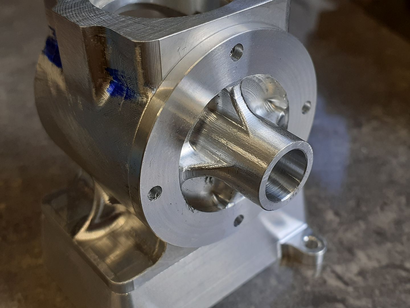
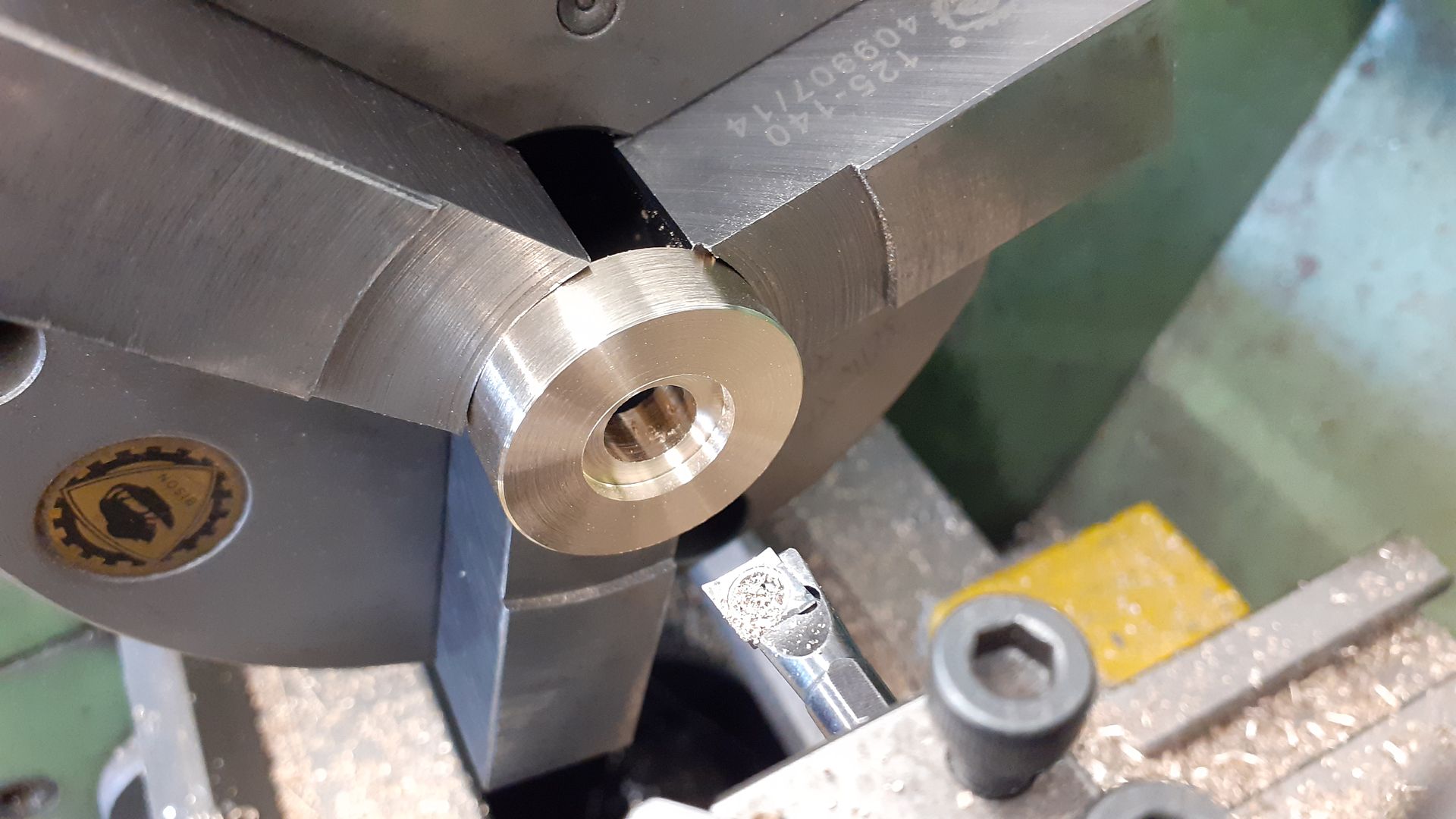
                  With that part complete I turned my attention to the end covers which are almost identical, the only difference being that one has a parallel area that the ignition timing disc can rotate on and the other at the flywheel end is as "cast". The first thing to do was bore out for the bronze bearing, turn the OD and also cut a spigot to fit into the crankcase.

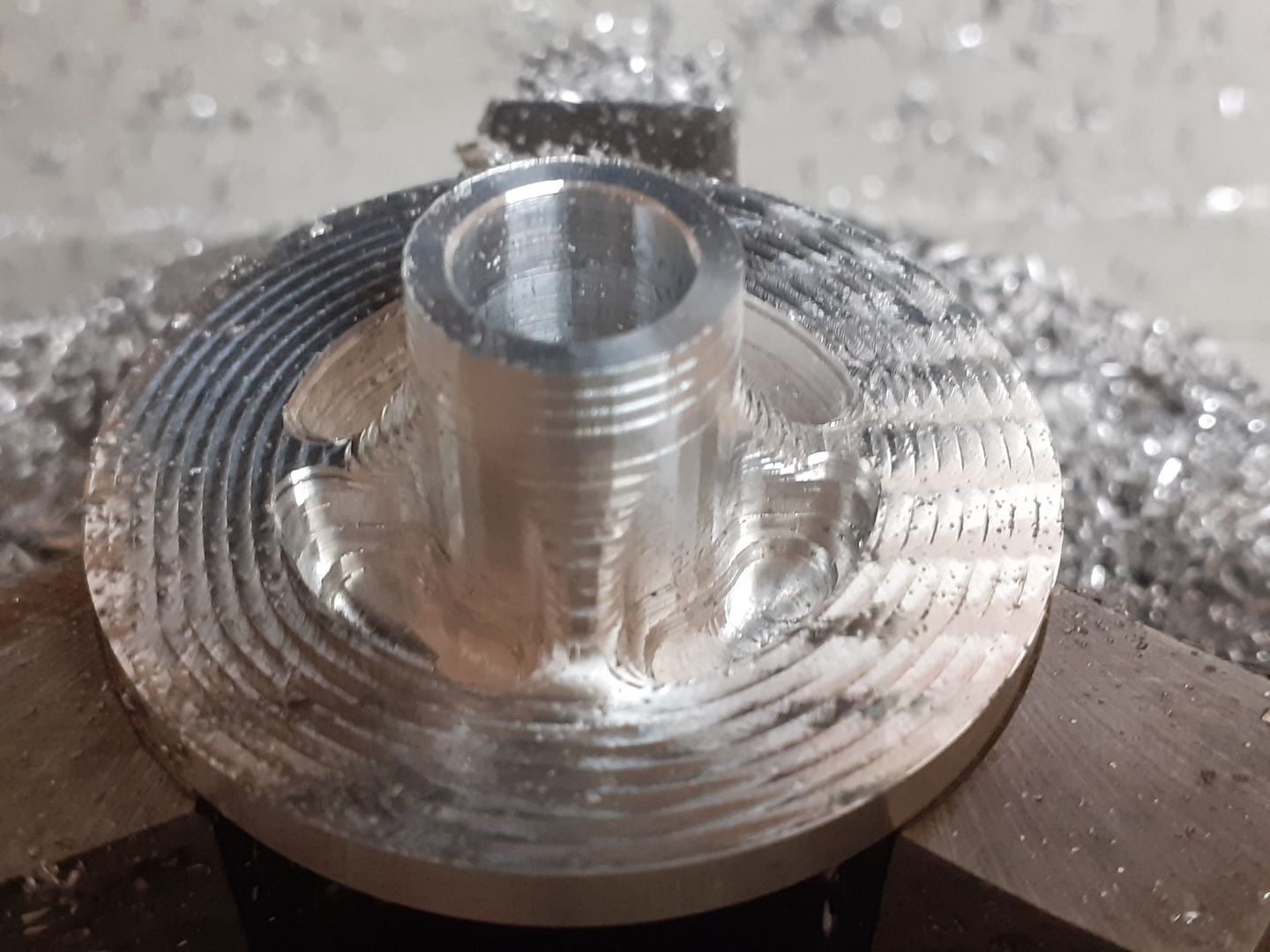
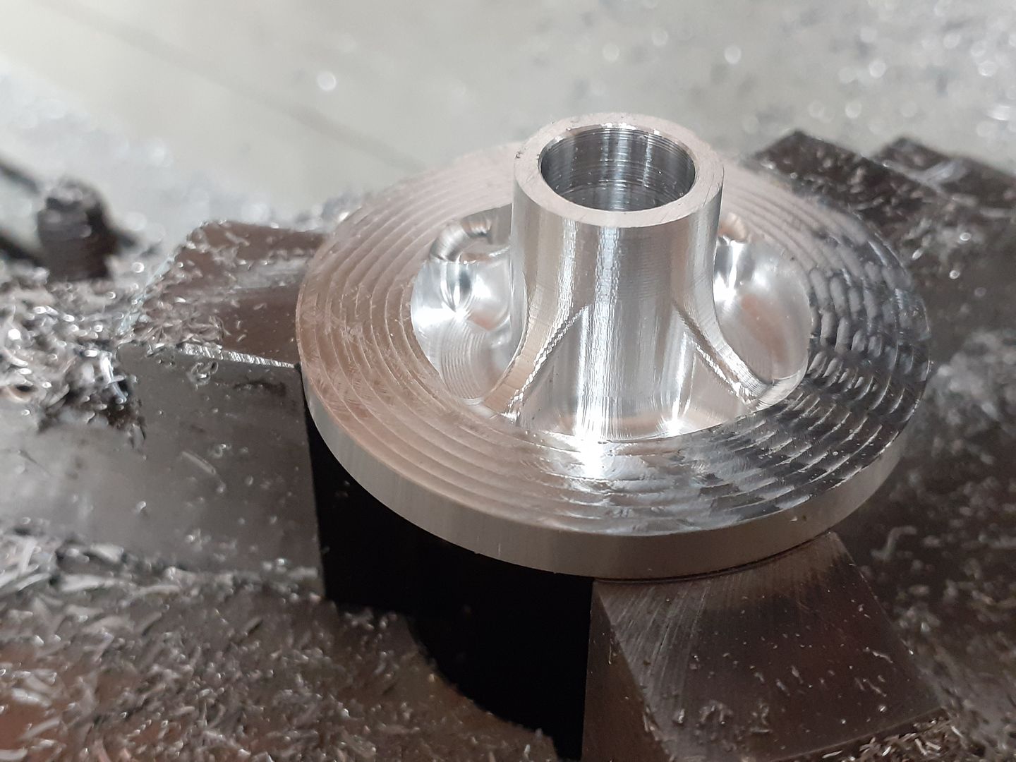
                  Having previously carved out similar details for the Stuart Lightweight on the manual machines I again took advantage of having the CNC to shape the external pockets leaving the webs that support the bearing housing. First roughing out

                  Then a finish cut with finer stepover

                  When doing the CAM I had set it to leave 0.3mm on the bolting face so the part was returned to the mill and skimmed to finished size, as this surface was going to be left as bear metal the turned surface looked a bit nicer than the CNC milled one.

                  While the mill was covered in aluminium chips I also made the base, this was just drilled and tapped twice from below so it could be held to a smaller block which in turn was held in the mill vice. This allowed for easy access all round the part. Not so easy to see but the outer edge has a draft angle machined into it to more closely represent a casting.

                  #594163
                  JasonB
                  Moderator
                    @jasonb

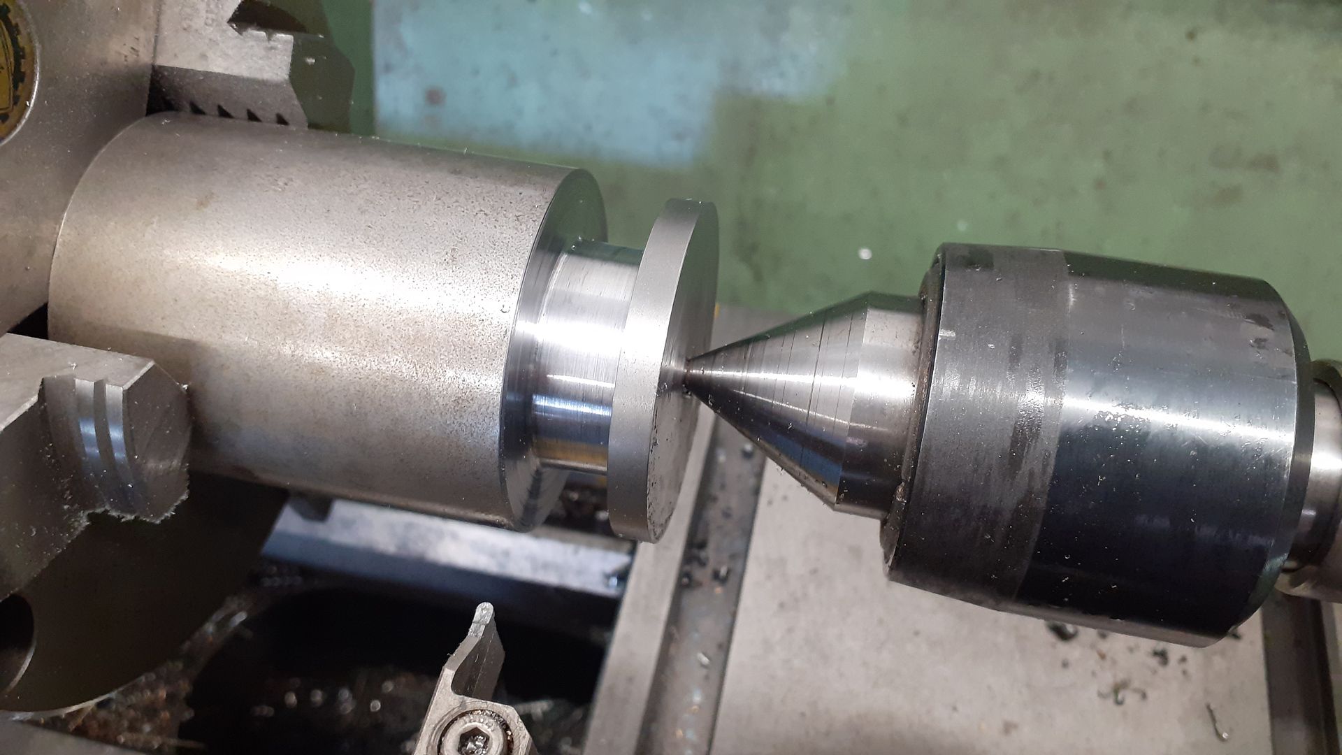
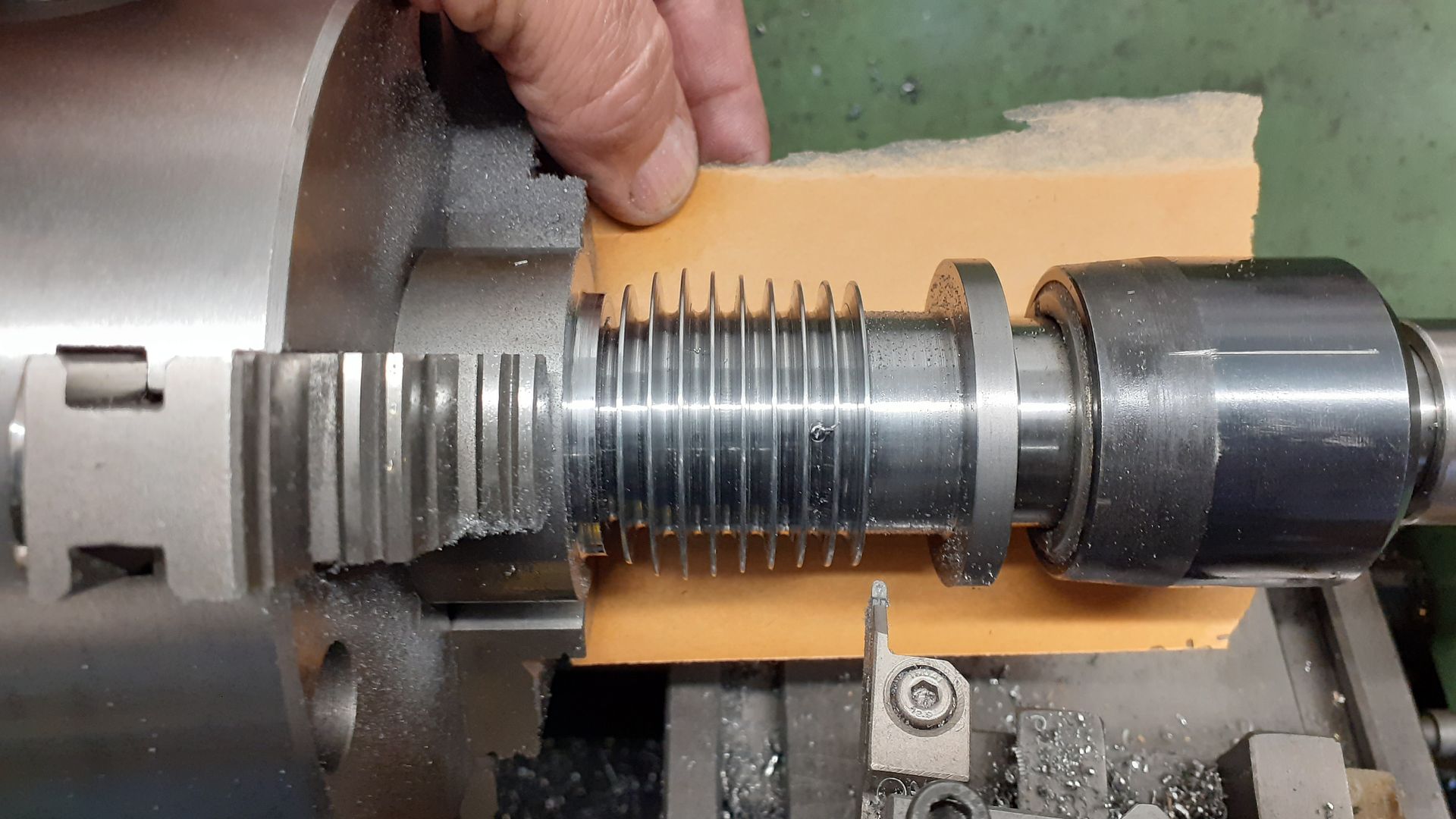
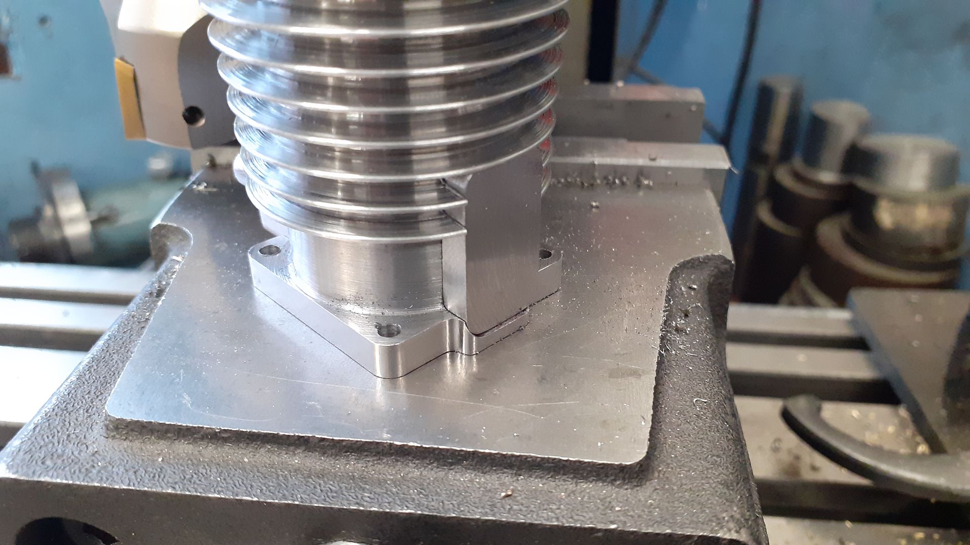
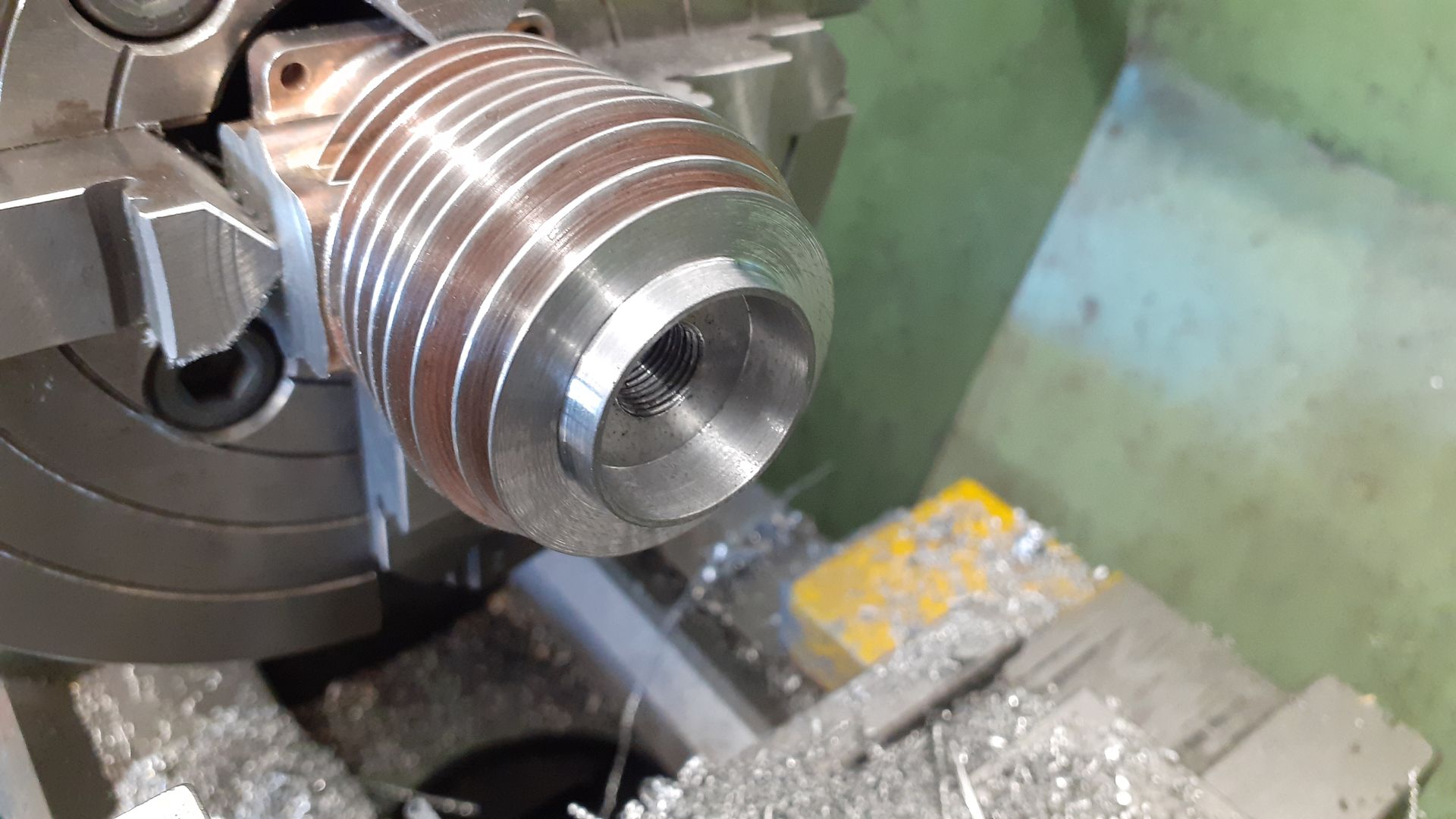
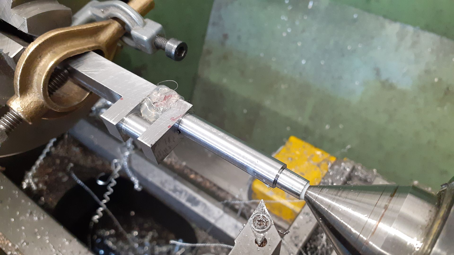
                    The cylinder started life as a piece of 50mm dia steel bar, faced and ctr drilled for tailstock support so that the waste above the mounting flange could be removed. I did most of this with a parting tool then switched to a 1mm radius end grooving tool so that I got some fillets left in the corners as it was brought down to final size.

                    I then roughed out the cooling fins with the same parting tool and finished with the groover, this took a bit of setting up as due to the change in length of the fins the angle of each changed slightly as the spacing remains constant.

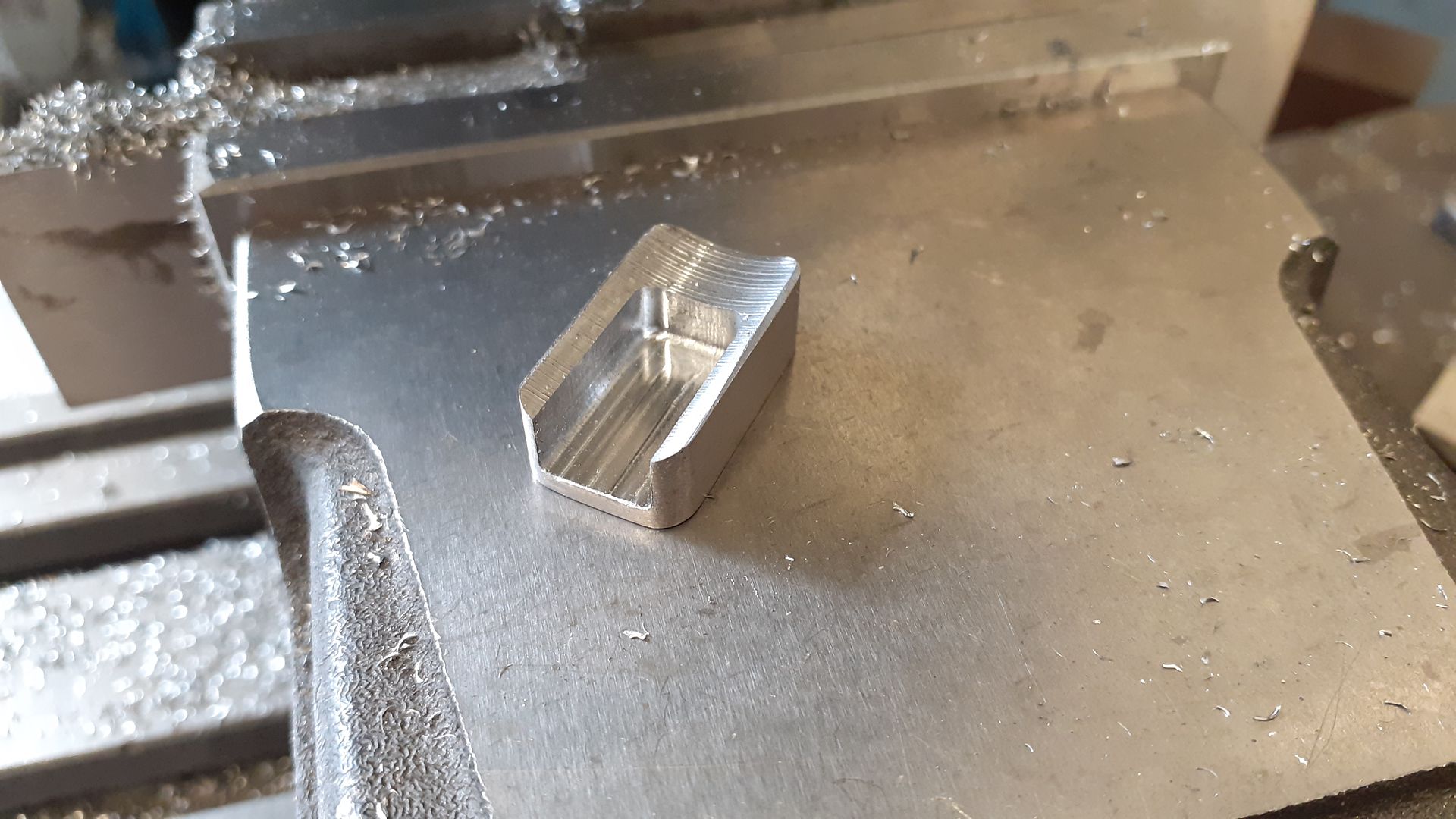
                    I used the CNC to cut the shaped holes for the inlet/exhaust boss and the simpler shaped transfer block

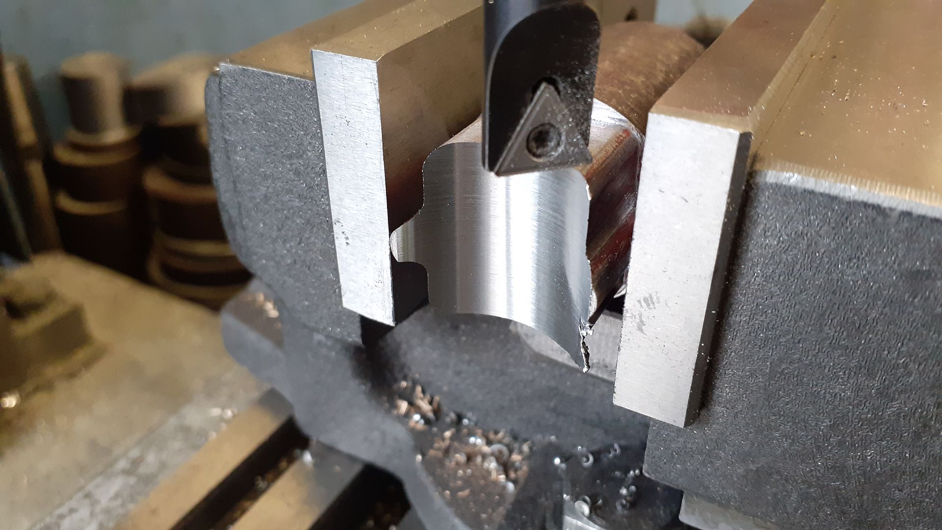
                    I also made use of it to cut the profile of the blocks on the ends of a bit of round bar, these were then cut to the undersize inner radius of the cylinder using a boring head

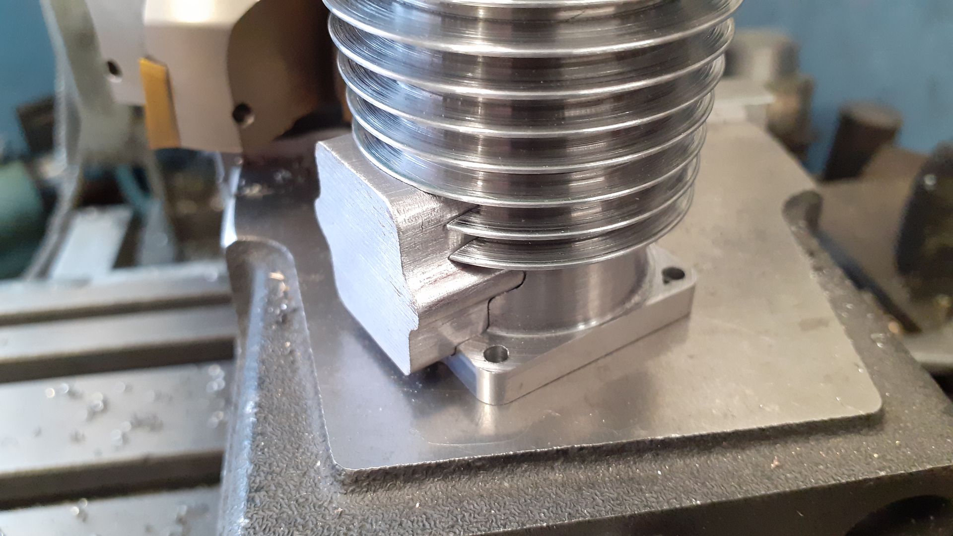
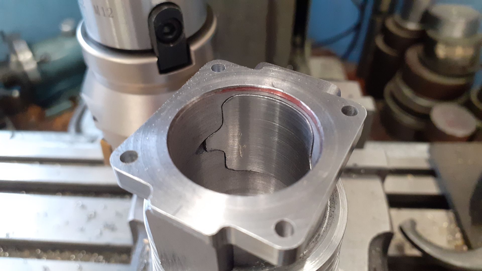
                    A trial fit showed that the CNC had done a nice job with close fitting parts that just needed one or two strokes of a needle file and then they could be lightly tapped into place with a small nylon hammer.

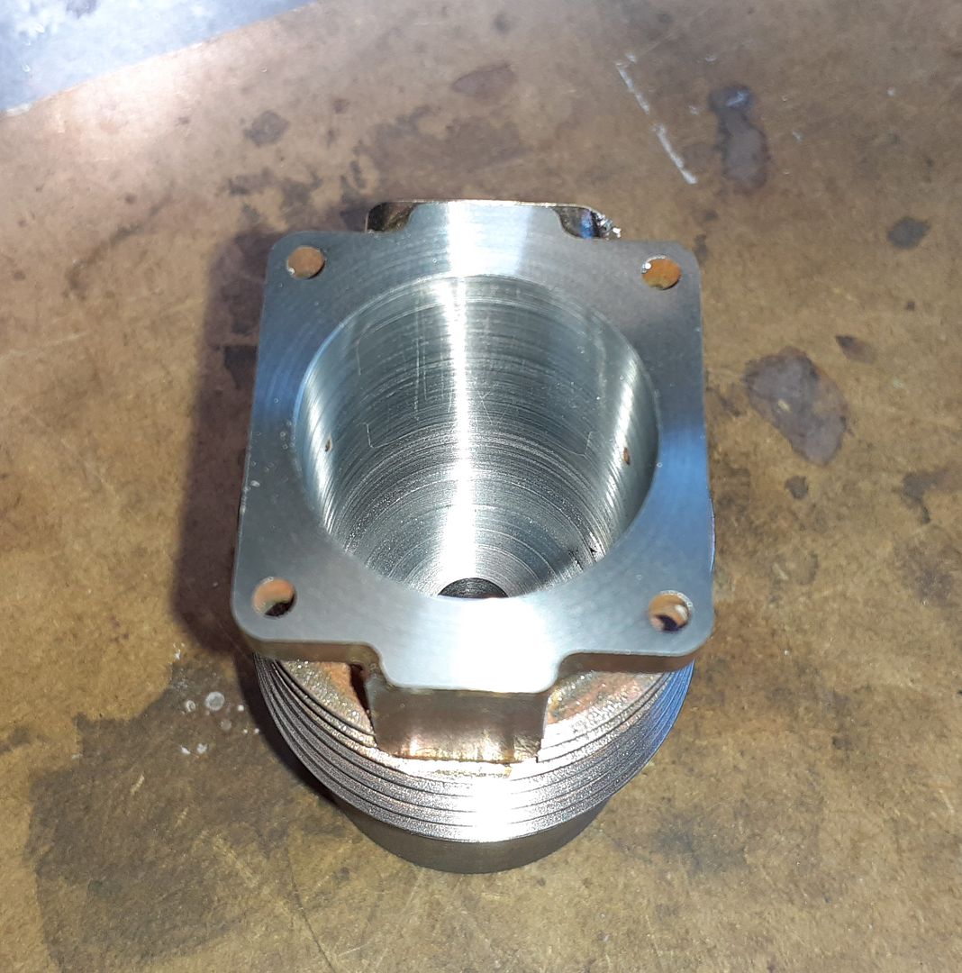
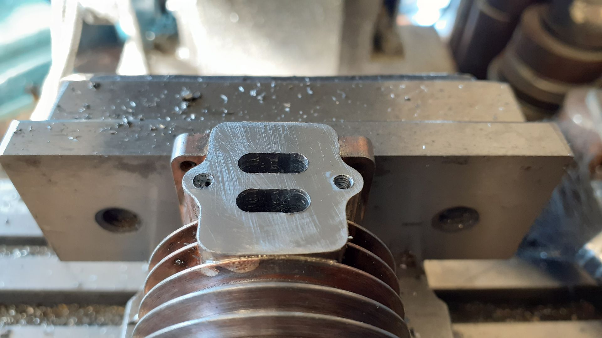
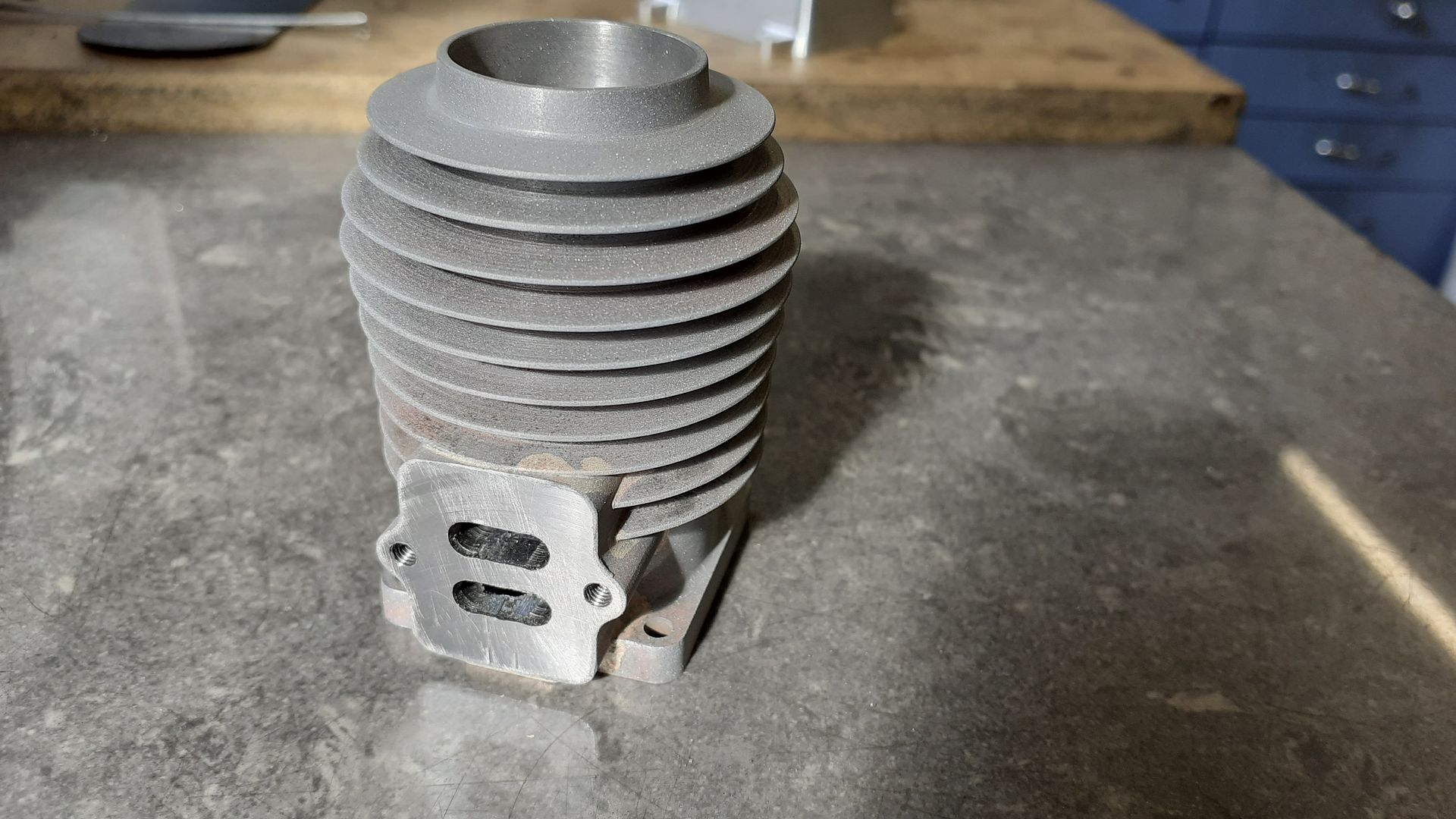
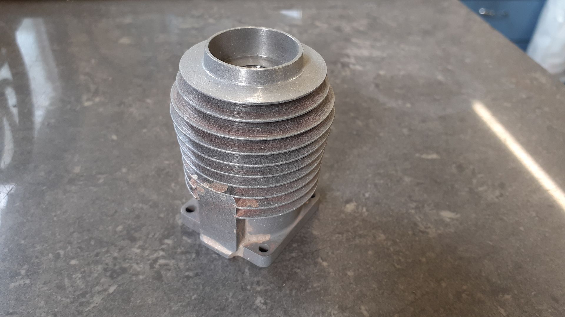
                    Happy with the fit the parts were cleaned and fluxed before silver soldering together. After machining the inlet/exhaust boss to finished length it was back into the lathe to Finish bore the inside to accept the iron liner. Once that was done and there was no more need for a chucking piece the top of the cylinder was turned to profile and the M10 x 1 plug hole drilled and tapped. You can just see the every thin line of silver solder around the joint from the inside

                    The last bit of machining was t mill the slots for intake and exhaust and tap two holes M3 to hold the combined manifold in place.

                    Lastly I grit blasted the outside to remove any discolouration from soldering and give a good key for the stove paint I had planned for it.

                    #594324
                    DiogenesII
                    Participant
                      @diogenesii

                      Well I think it's an awesome bit of work – by both man and machine.. ..please keep it coming..

                      #594729
                      JasonB
                      Moderator
                        @jasonb

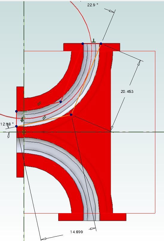
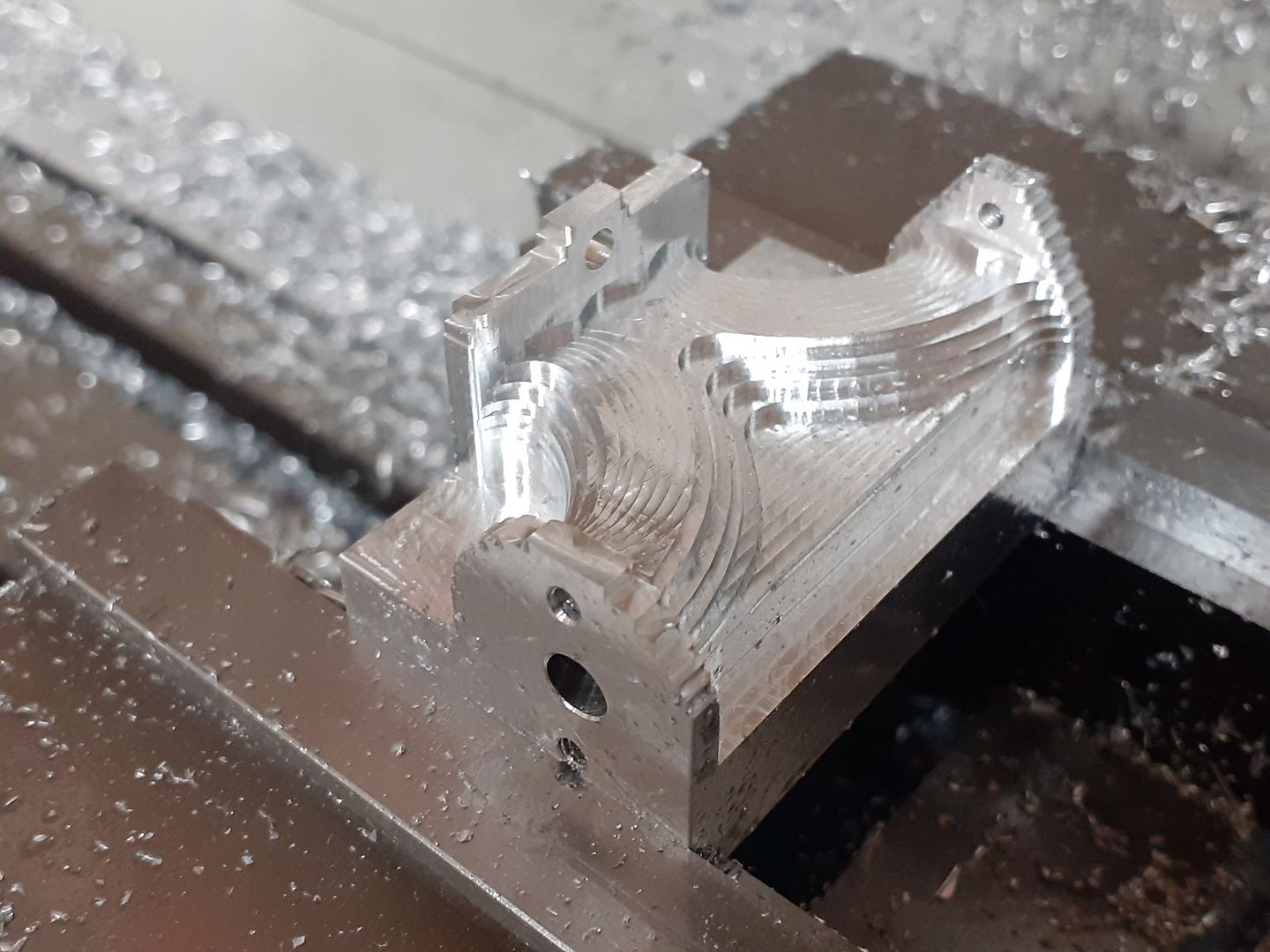
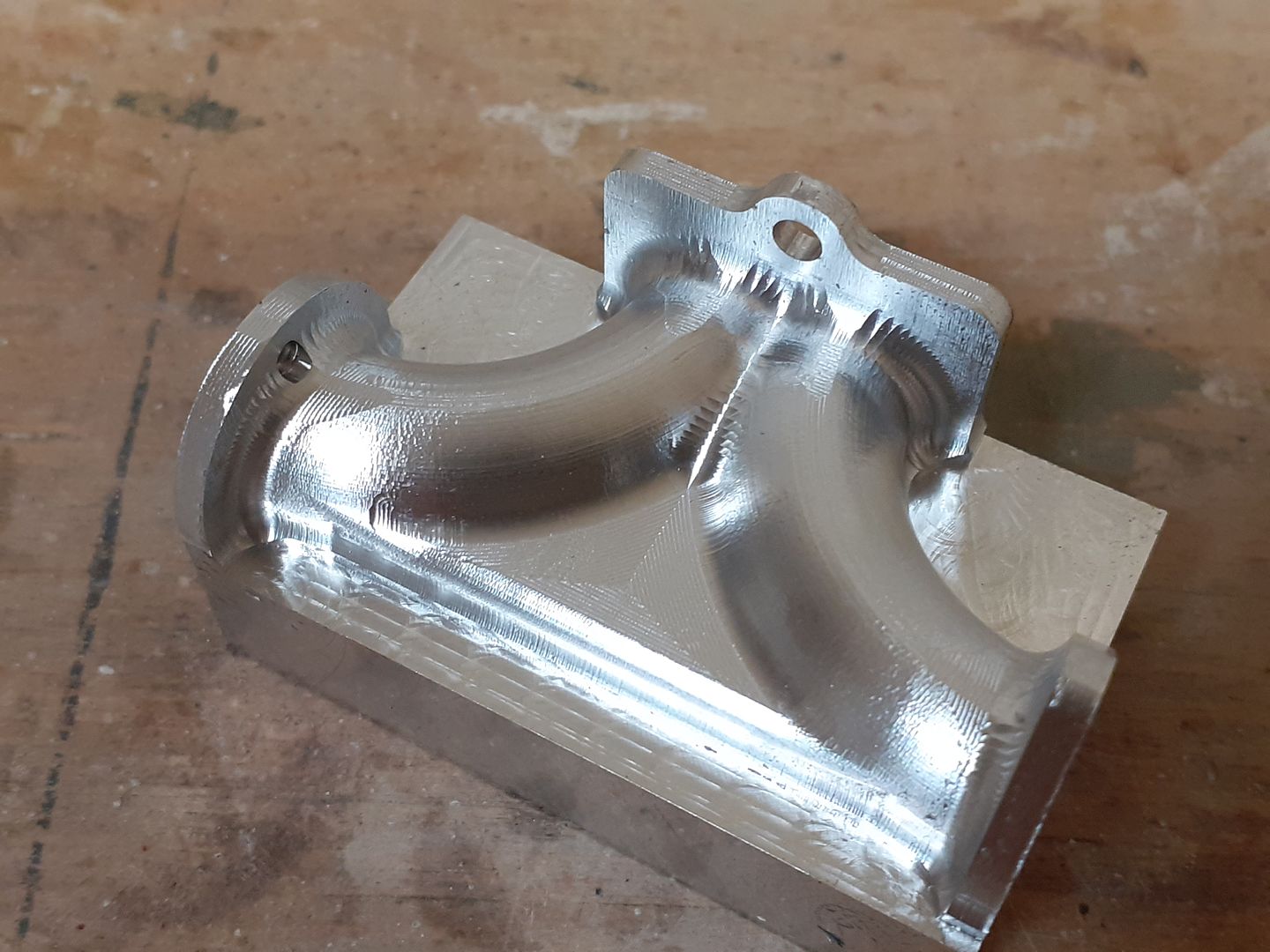
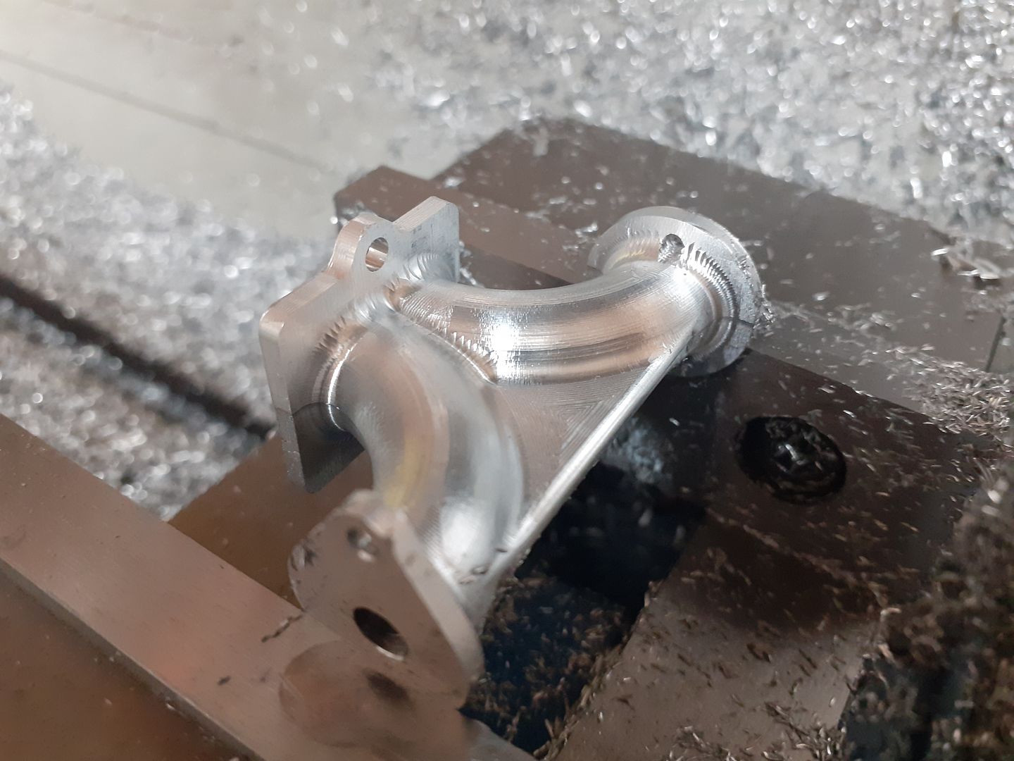
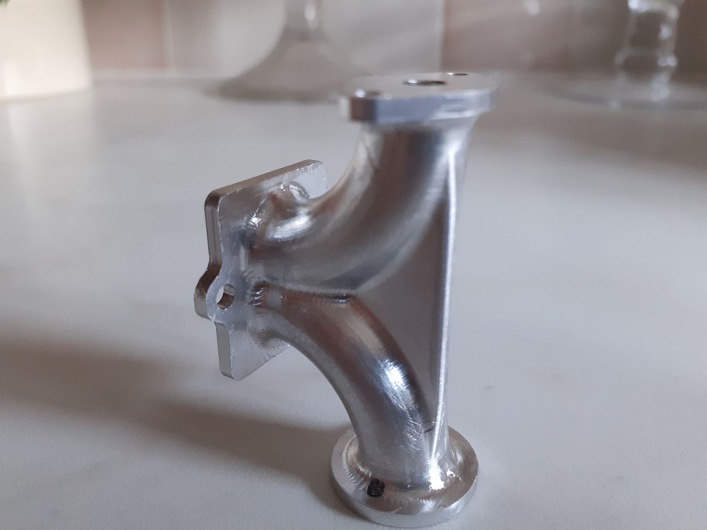
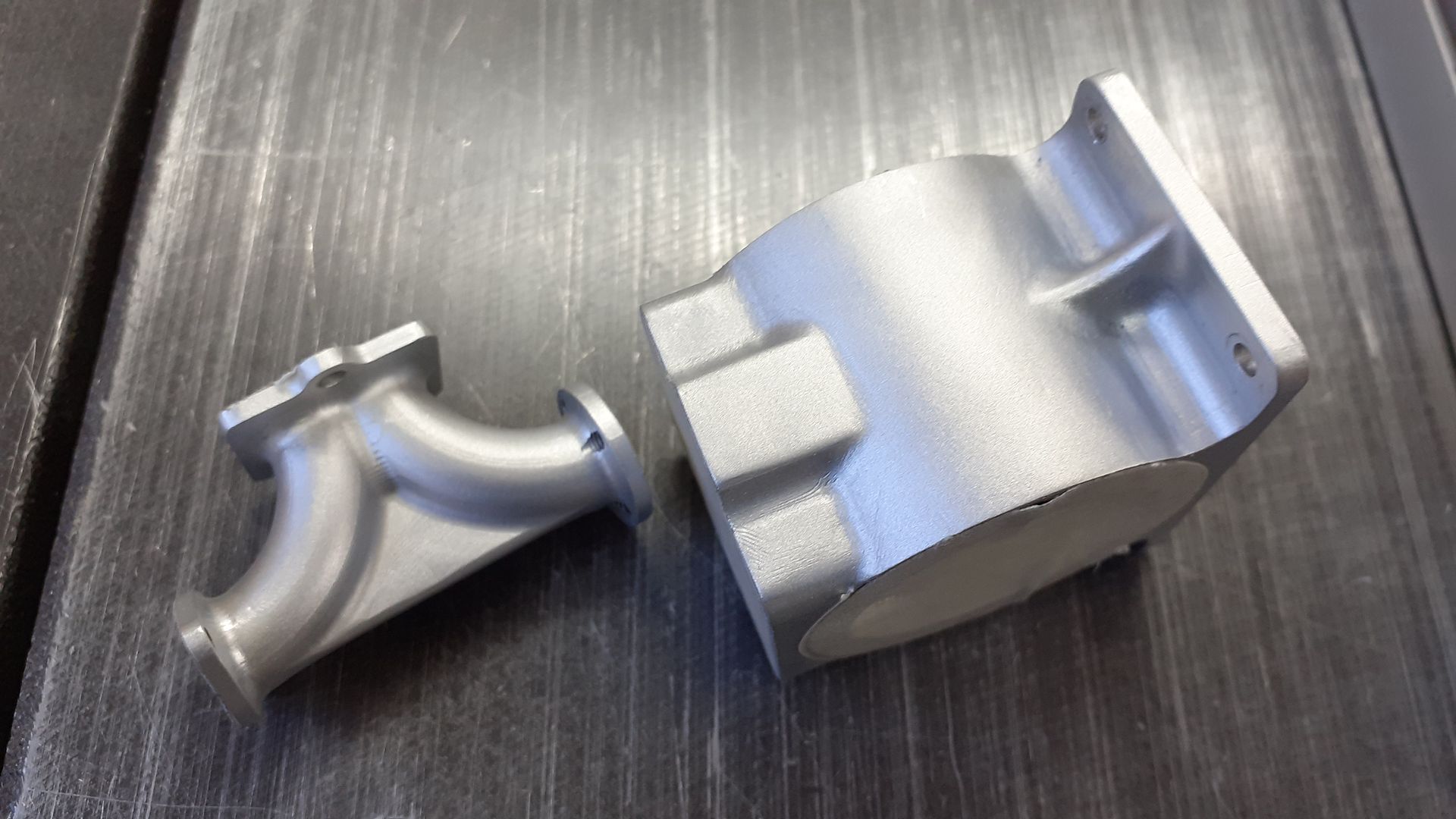
                        The engine has a rather shapely combined inlet and exhaust manifold that would have been an aluminium casting on the original and is an ideal candidate for CNC machining as that handles the curves very well. The passage s would have been cast in using cores and I did toy with the idea of making in two halves in brass so the passage could be milled out and then solder the two together. In the end I worked out tat a couple of carefully placed drill holes would meet in the middle and hopefully not come out the side so a one piece aluminium part was on the cards. You can just see the orange ctr lines of the holes on this drawing together with their depths and angle of drilling.

                        A block of 6082 was machined to overall size and held in the vice to first rough out to half depth using an adaptive tool path using a 4mm flat ended 3-flute cutter

                        .

                        Then the "steep and shallow" path was used while I still had access to refine the shape. I think that was a 3mm ball nose 4-flute cutter but may have been 4mm.

                        It was then put back into the vice the other way up and a mirrored version of the CAM used to complete the other side as the top and bottom flanges are different shapes.

                        I'm quite pleased with how it came out, probably should have run a "pencil" path that has the ball nosed cutter run along all the internal fillets which would have got rid of the slight steps.

                        I spent a little while smoothing this and the crankcase casting with needle files and then had a go at bead blasting them with a very basic Aldi spot blaster which gave the desired finish but I need to get small cabinet as glass beads on the garage floor can be a bit slippery ;D

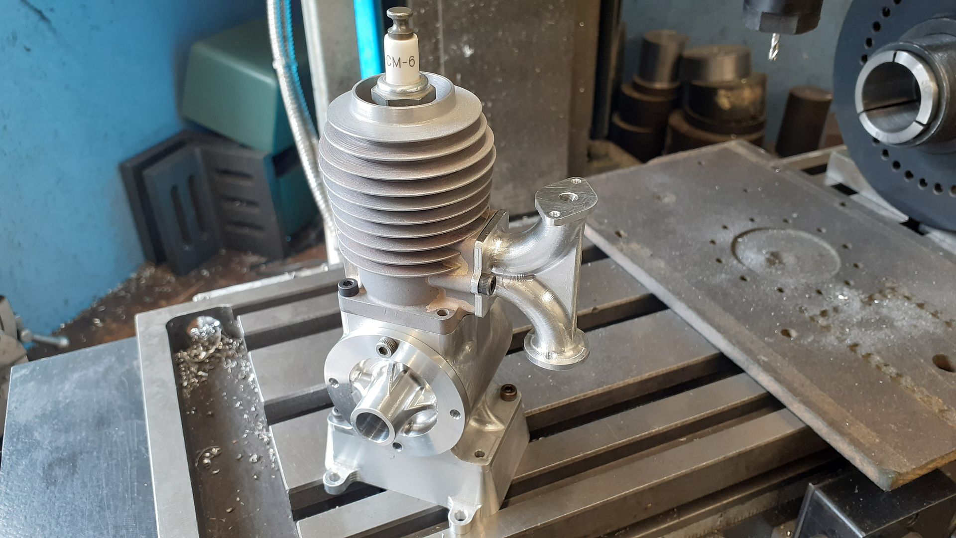
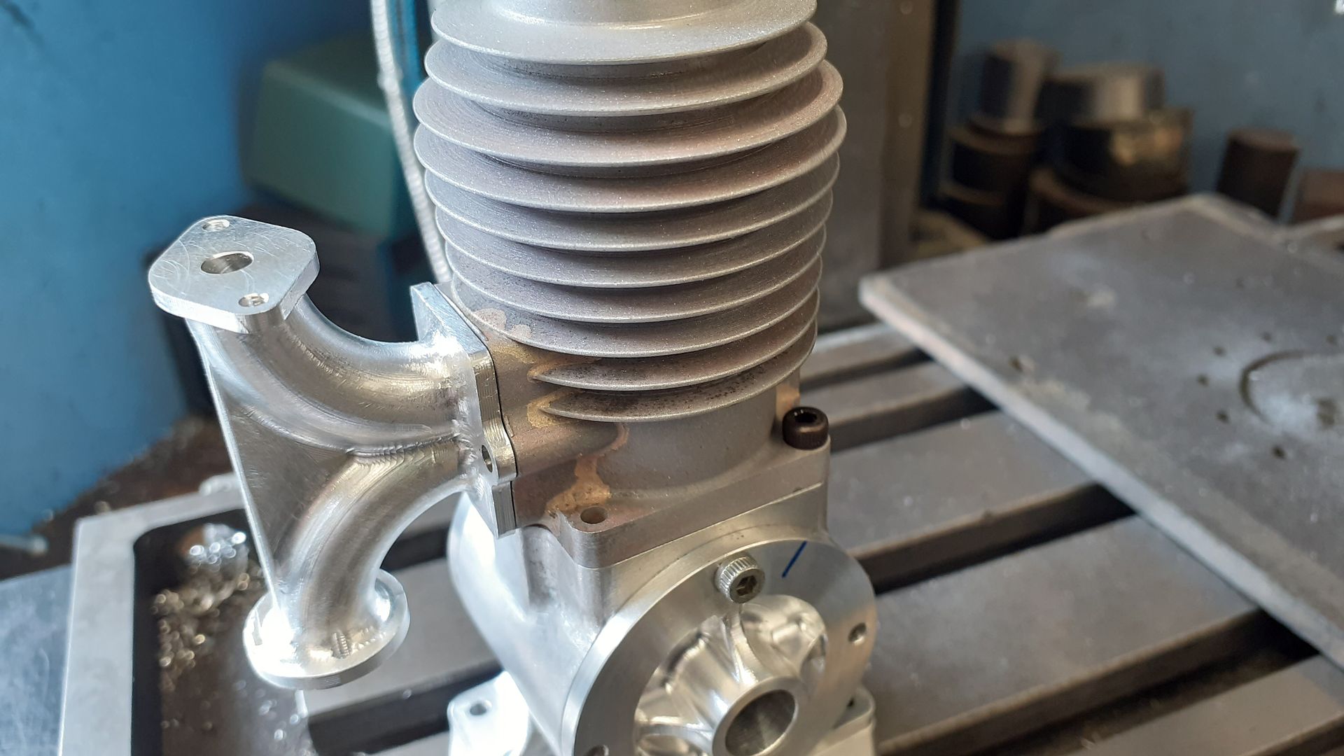
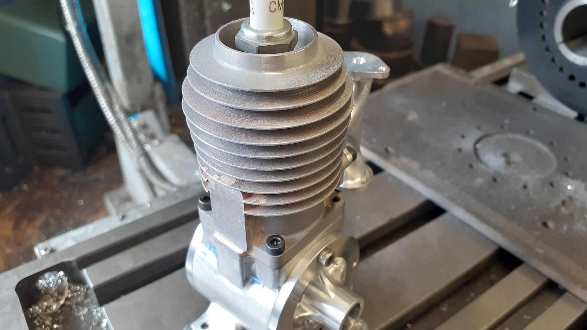
                        A couple of photos of the engine coming together taken prior to the bead blasting to round things off for tonight.

                        #594734
                        Jon Lawes
                        Participant
                          @jonlawes51698

                          This is superb.

                          #595310
                          JasonB
                          Moderator
                            @jasonb

                            Thanks for the interest

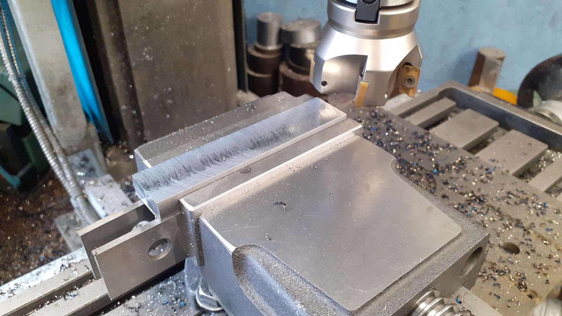
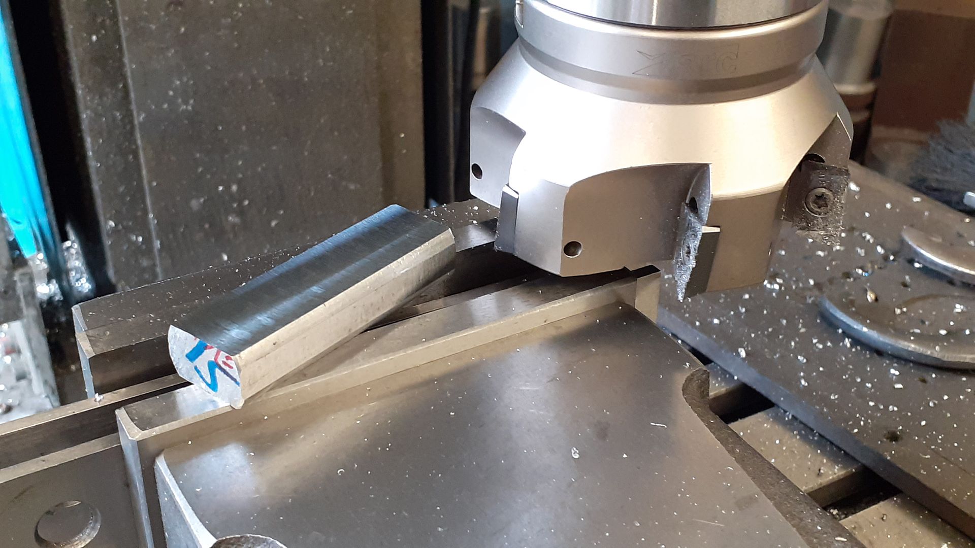
                            The crankshaft started life as a length of EN8 round bar and was reduced down to a rectangular section using a 5 insert face mill regularly flipping the bar over to minimise the risk of any distortion caused buy taking a lot of metal off one face in a single go.

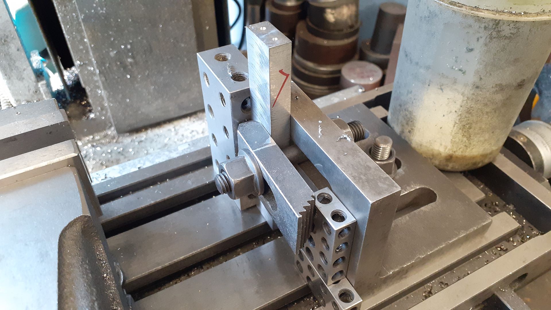
                            I then used an angle plate and 20-40-80 block to give me two reference faces to clamp the now rectangular bar to so that the ends could be centre drilled ready for subsequent turning

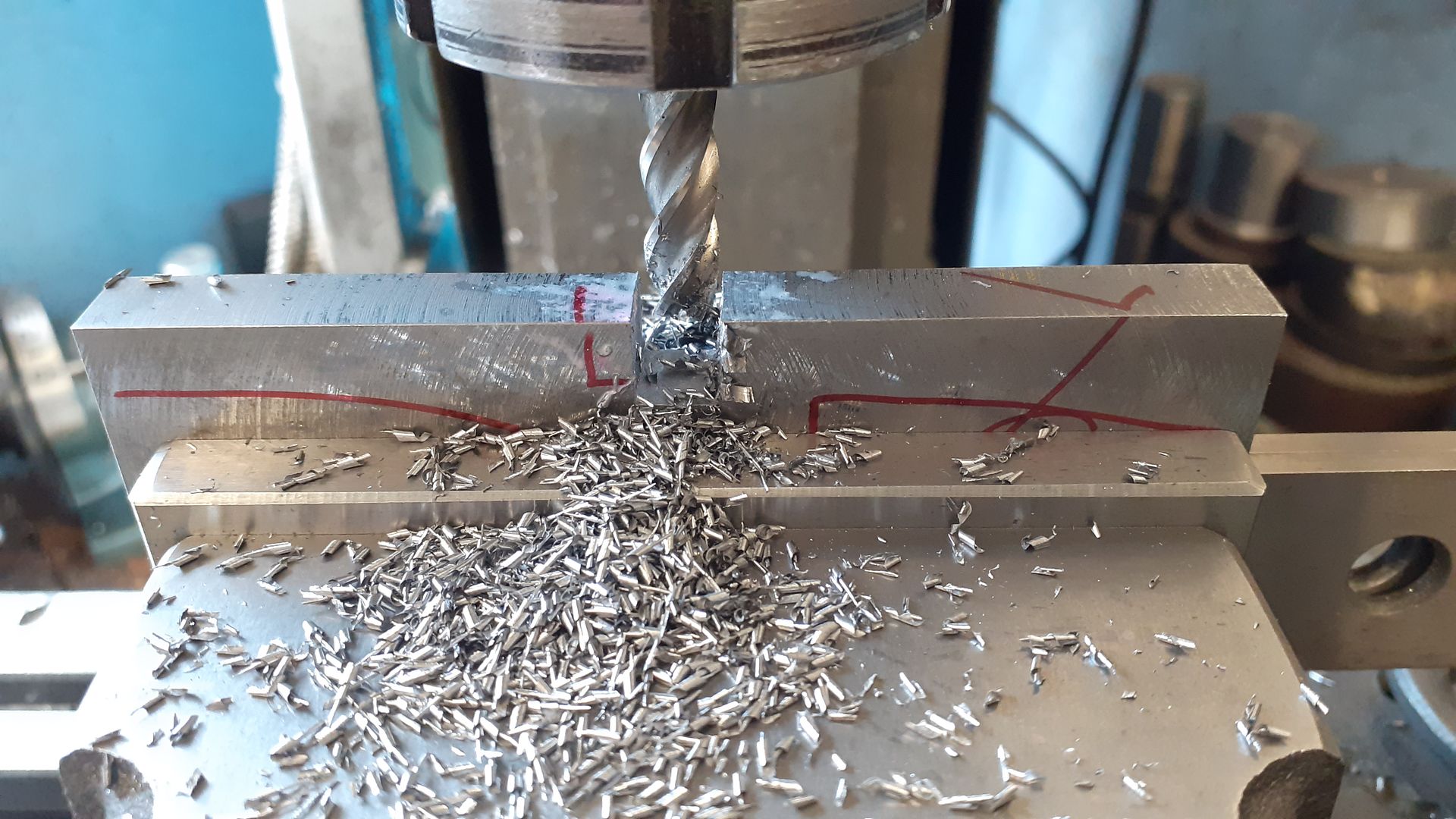
                            To avoid the knock, knock, knock of the interrupted cuts I milled out most of the waste between the webs with a 10mm cutter. A good example to those new to milling of the type of chips they should be producing rather than dust, I think I was cutting in 2mm deep passes the full 10mm width of the cutter. As the slot was just to remove waste I used a 4-flute, the turned finished width was 12mm so no worries if it did not mill to an exact size

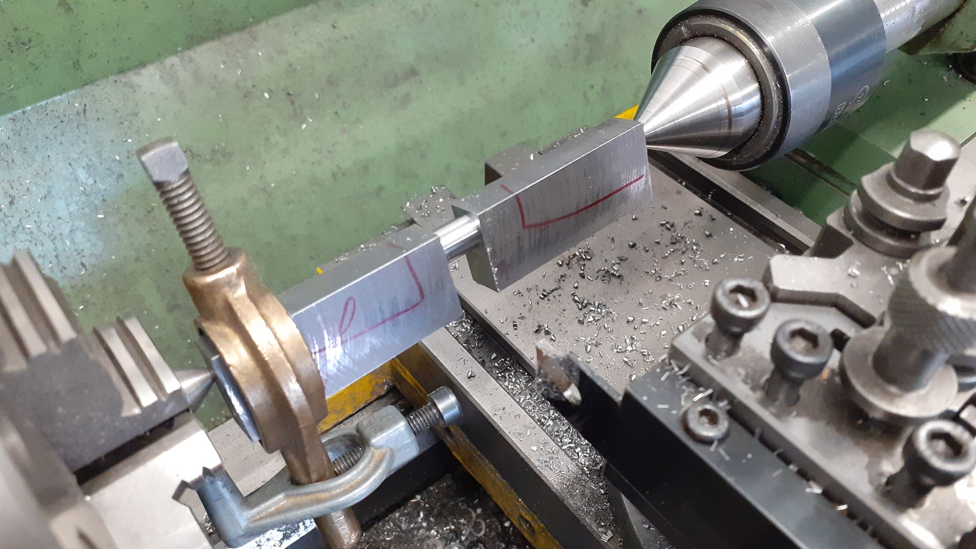
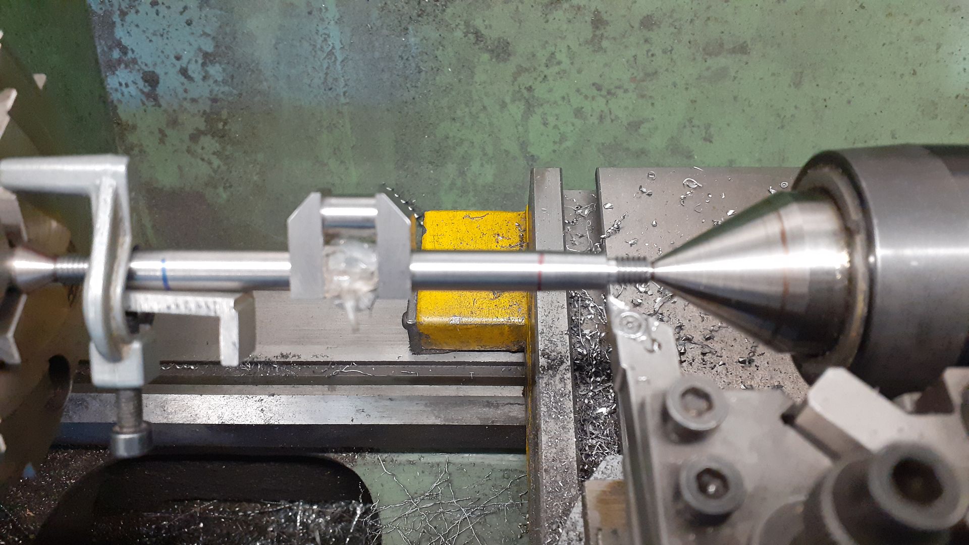
                            Over to the lathe and a soft ctr held in the 3-jaw was trued up and the chuck jaws also work well to drive the dog. I use a GTN2 insert that has been modified with a Dremel cut off disk to remove the cutting edge in the middle to do the last few finish cuts moving the tool from side to side

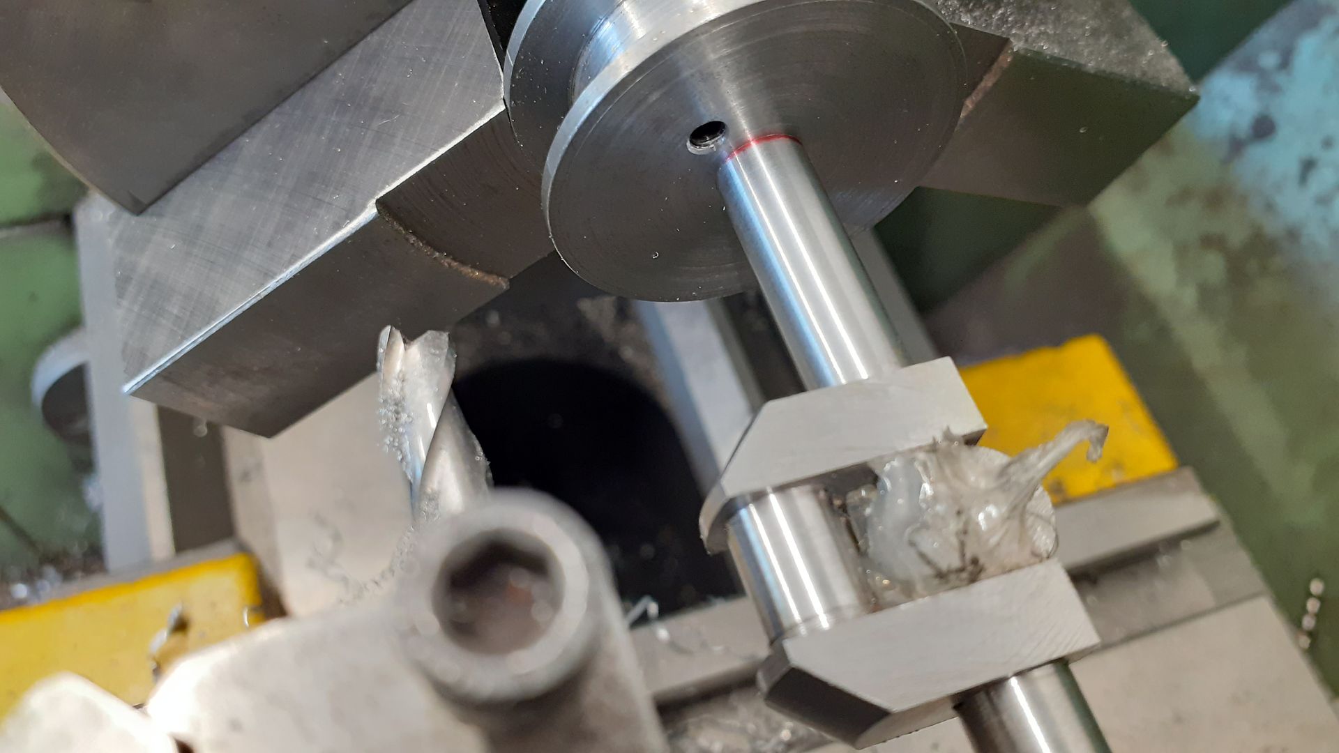
                            After milling away the waste at either end and fitting a packing piece between the webs the shaft was turned down to the required 10mm diameter 8mm diameter and the ends reduced ready to be threaded M6. The shaft was then set aside until the flywheel and pulley were ready so all the tapers could be cut with the top slide at the same setting.

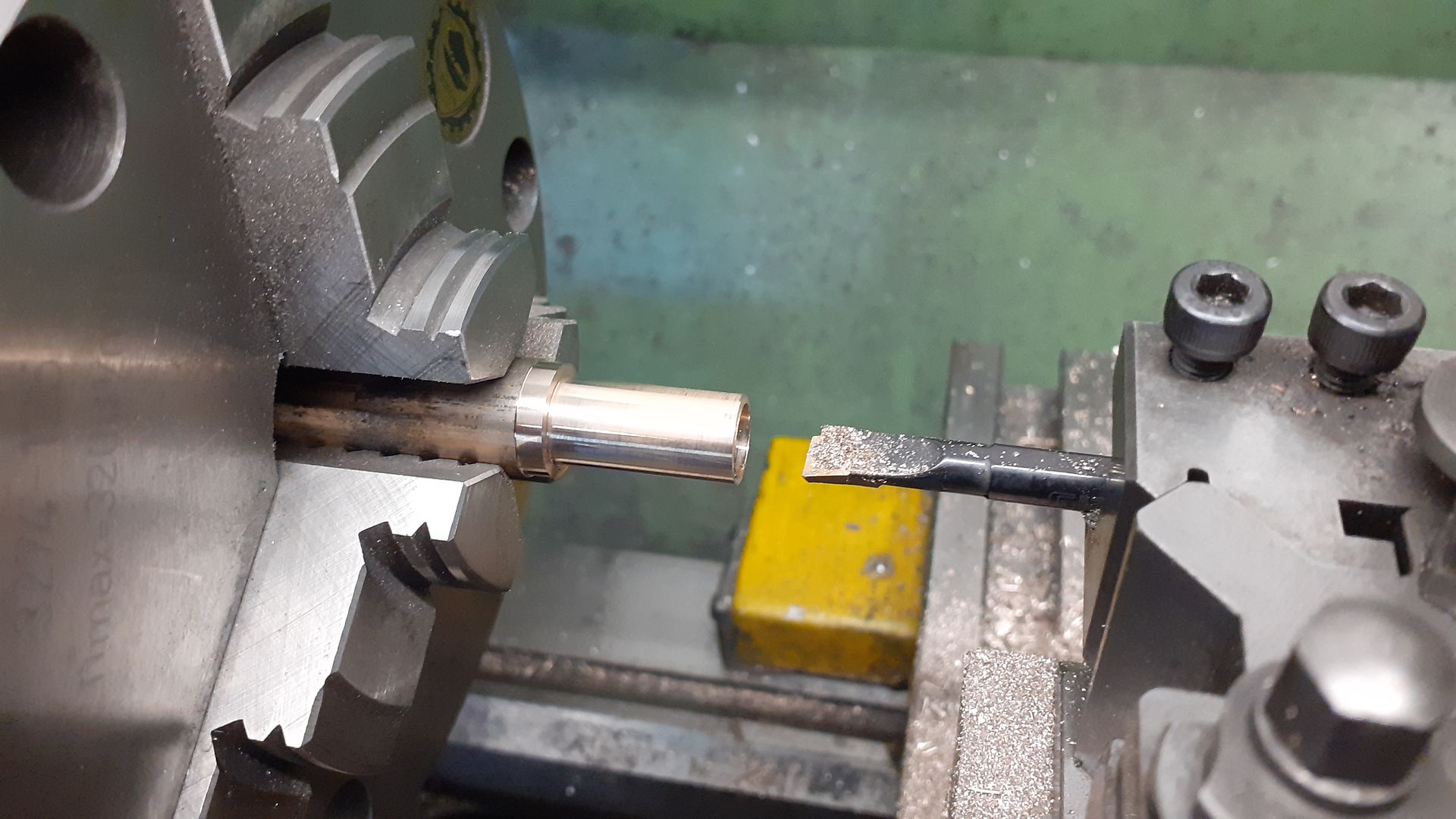
                            With the shaft diameters finished I could use that as a gauge to bore the bronze bearings which are just simple flanged ones

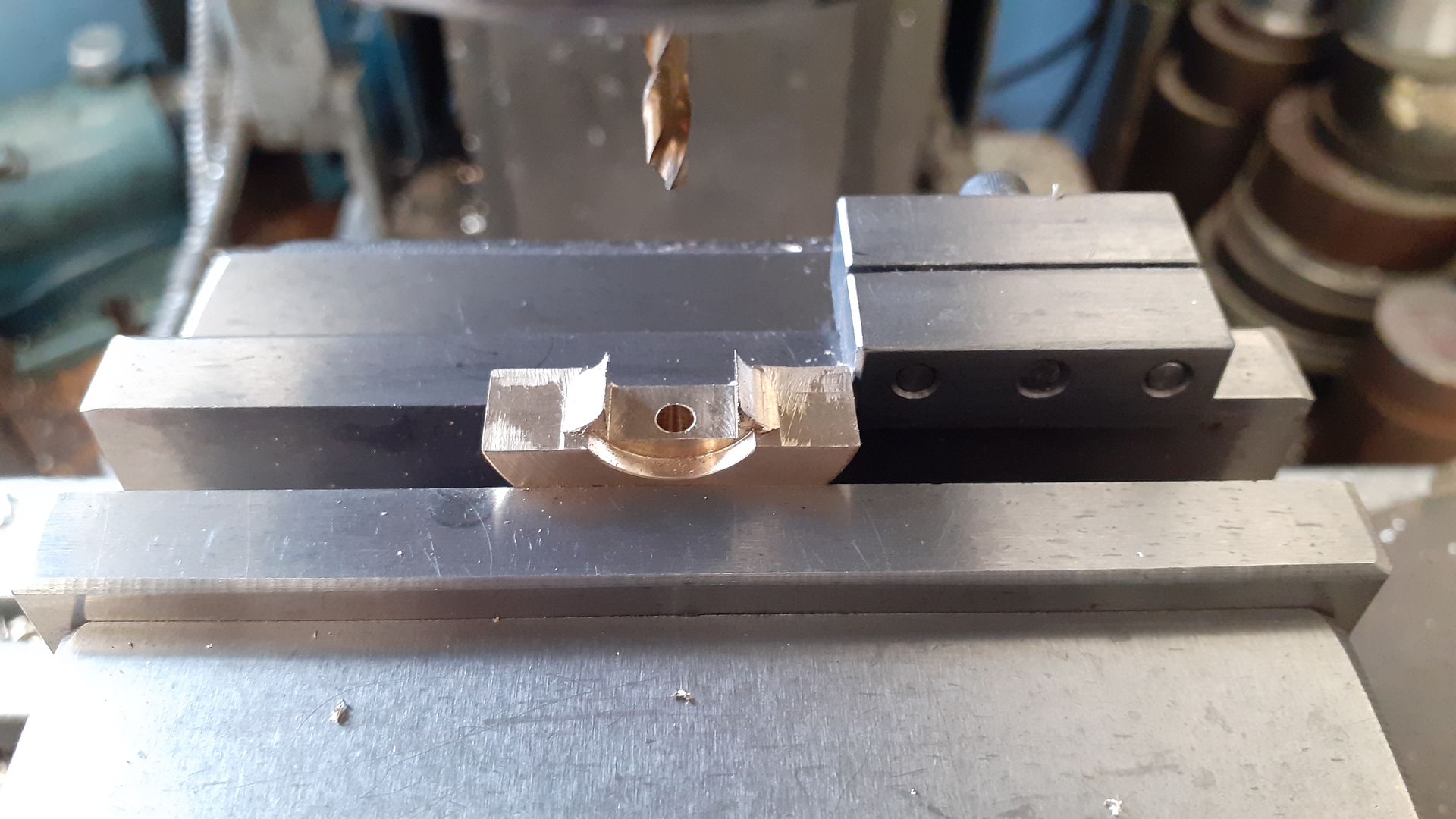
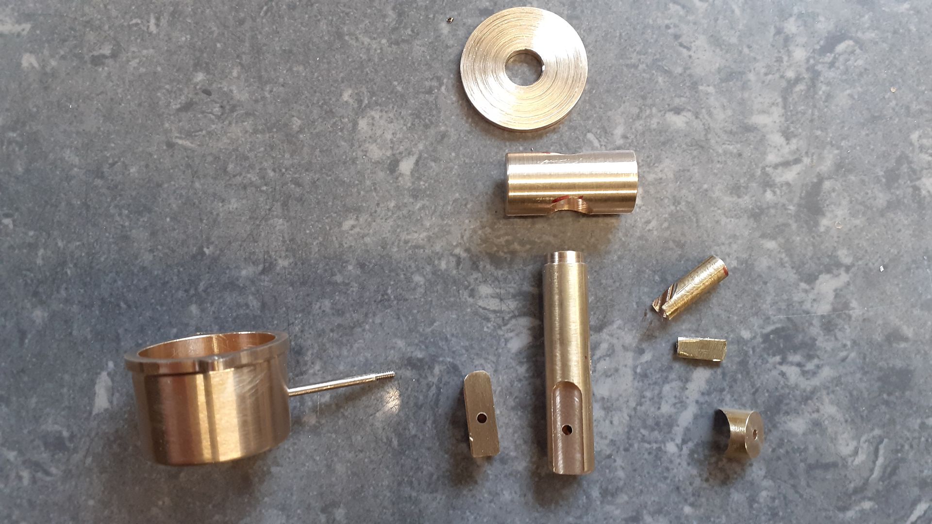
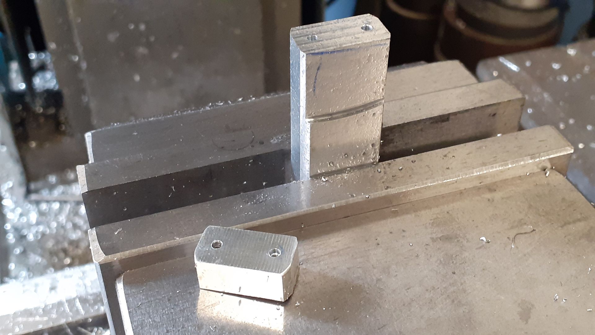
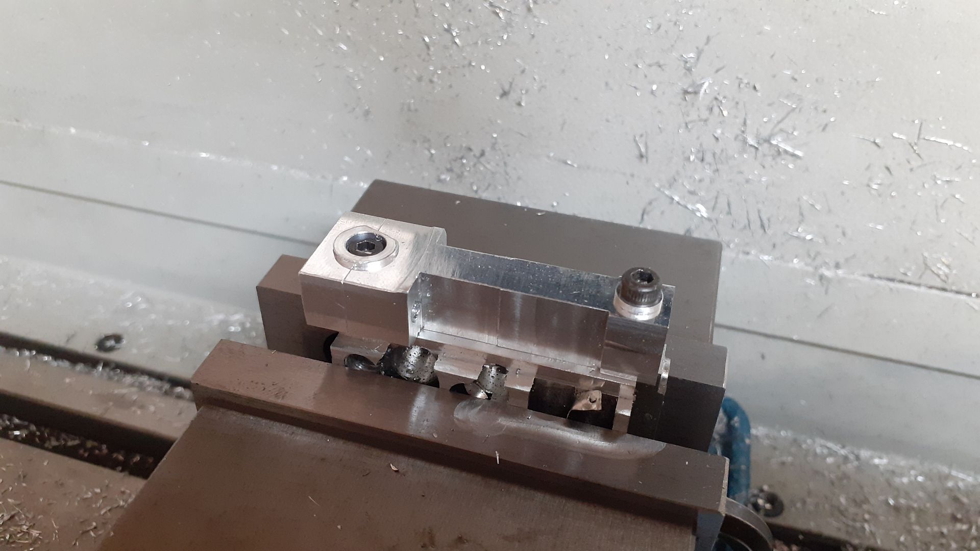
                            There are bolt on counterweights on the crank webs, I started by turning a piece of bronze.

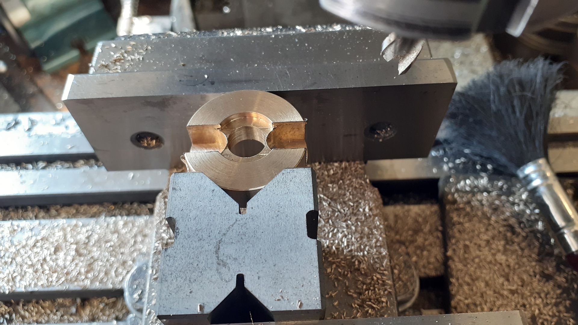
                            Then milled some slots to produce the two "half circle" weights

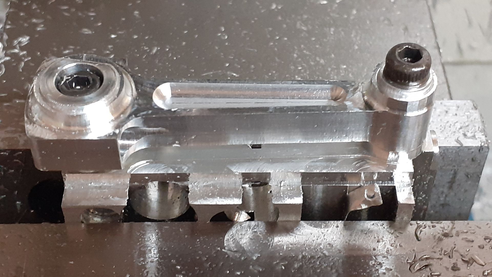
                            And then a slot to fit over the crank web's end and a hole for the retaining cap head screw

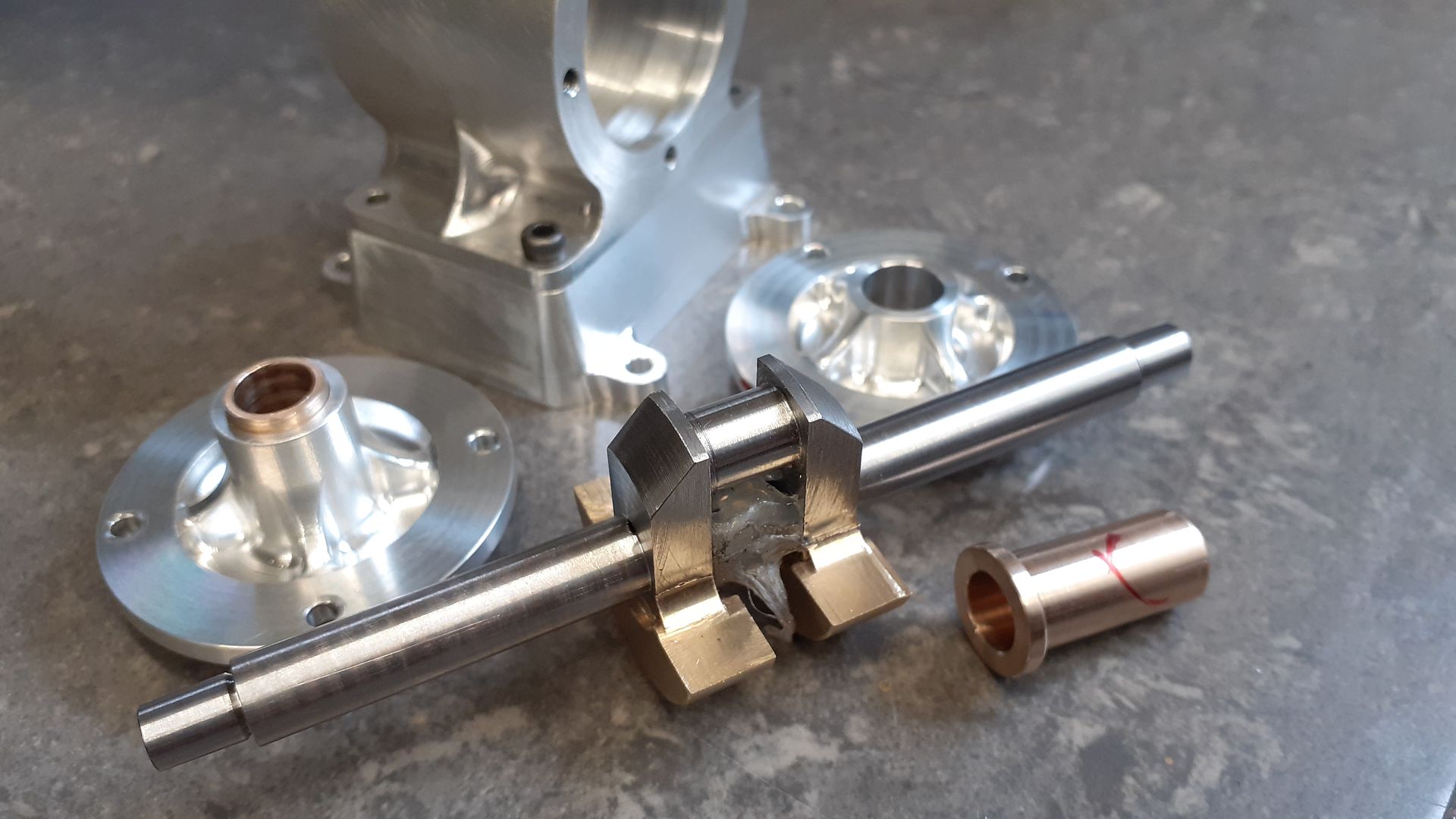
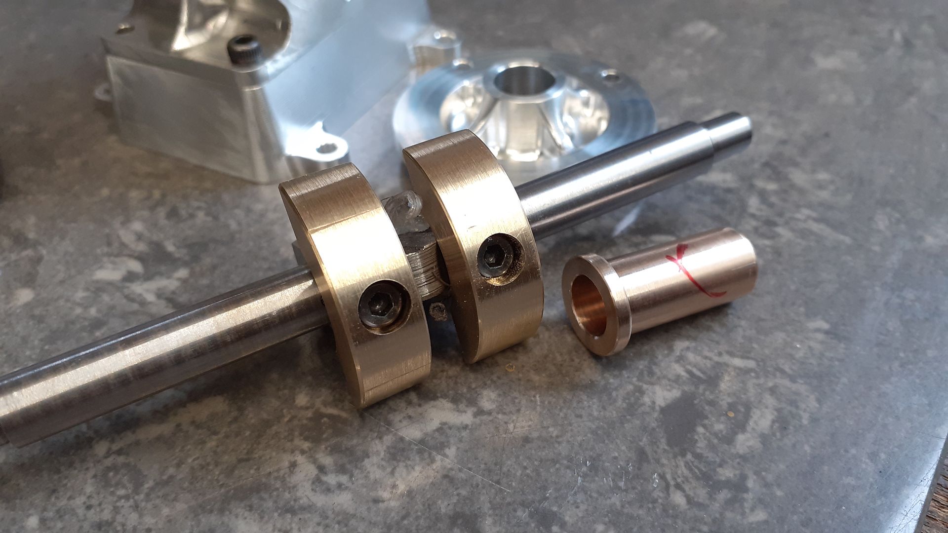
                            A couple of shots of the crankshaft with it's weights and the bearings one of which is fitted to an end cover.

                            #595445
                            DiogenesII
                            Participant
                              @diogenesii

                              ..and thanks for these updates & especially the pics – the devil's in the detail – like the little fillets on the bobweights; nice work.

                              #596609
                              JasonB
                              Moderator
                                @jasonb

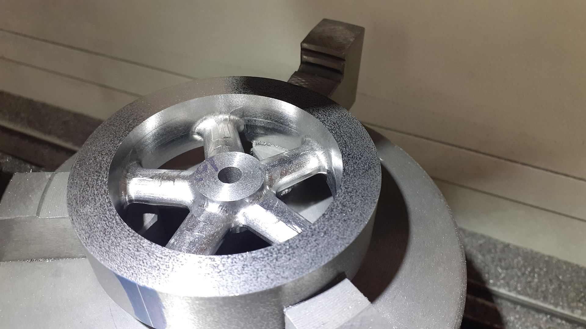
                                I did not take many photos of the flywheel being made as the process was very similar to others I have done. Basically a slice of cast iron bar was turned and bored undersize, some waste material removed on the manual mill before cutting the spokes on the CNC.

                                I also turned up the pulley for the starter cord and then it was safe to set over the topslide so all the tapers could be cut without disturbing it. First the two ends of the crankshaft were done.

                                Then the two bores. As the taper got smaller towards the headstock and the topslide was advancing the opposite way I needed to cut on the back side of the bore I needed to use one flute of a 3 flute cutter held in the topslide which worked well fiving a taper from 8mm down to approx 7mm with a little room to spare around the 6mm dia cutter. Here you can see me gauging the size using a park on the crankshaft to get the right length of taper into the hole.

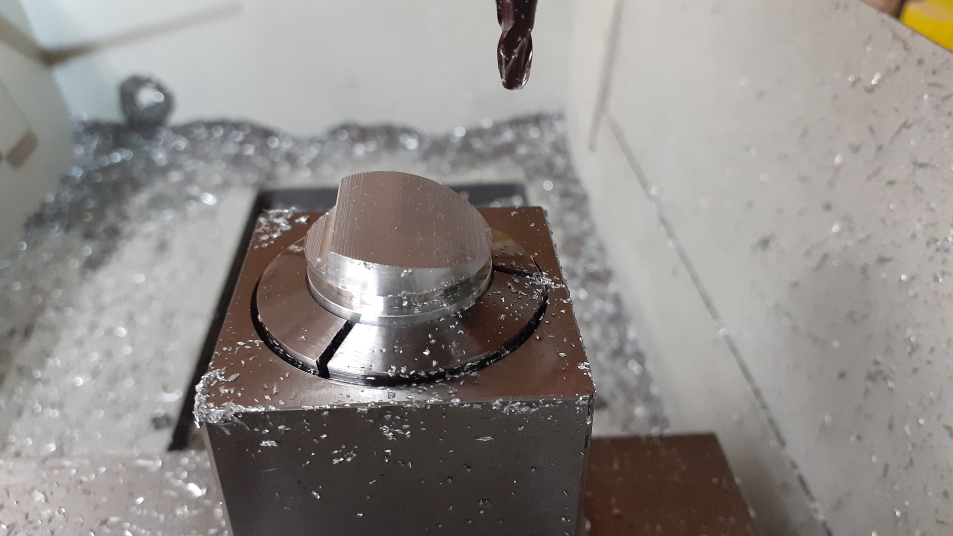
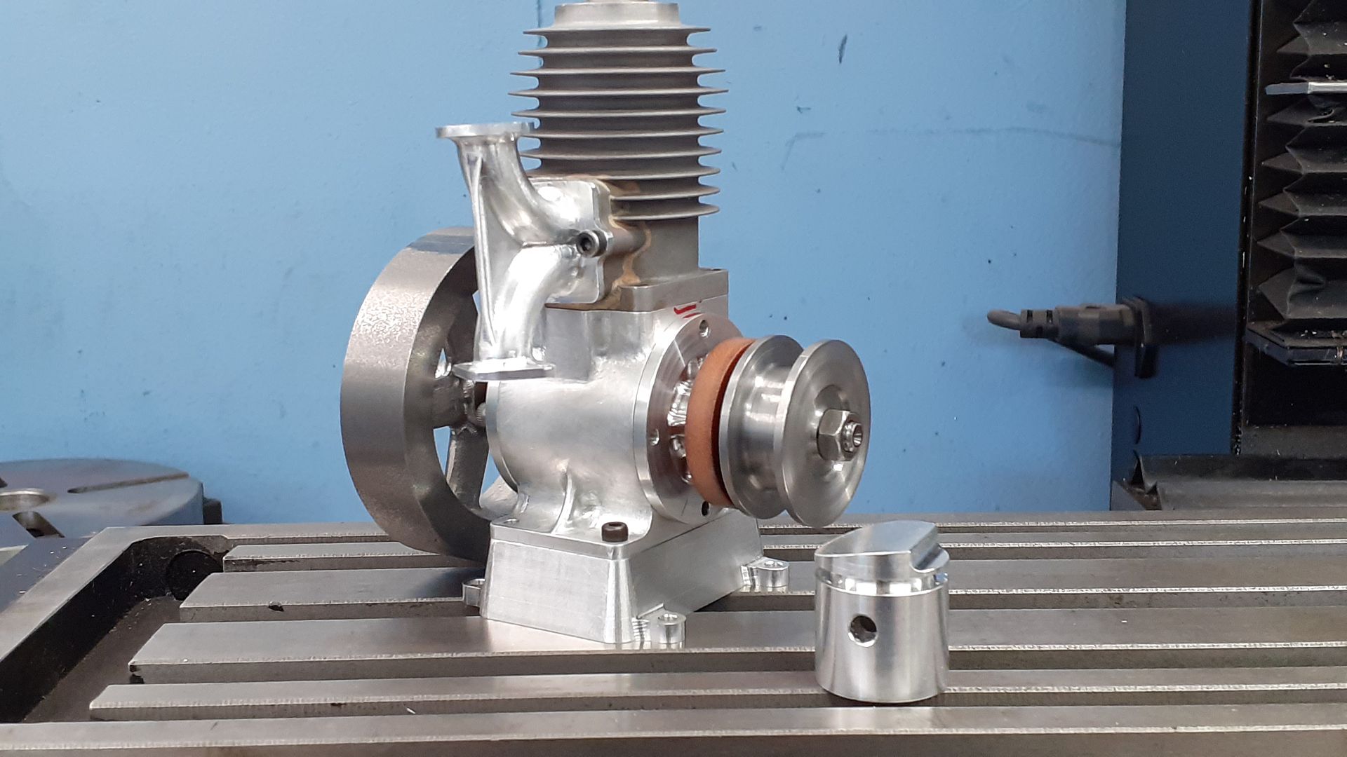
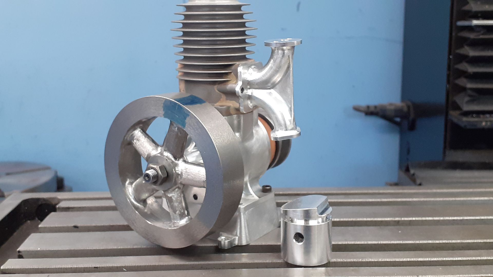
                                The piston was straight forward turning but I did use the CNC to form the dog bone recess in the underside as well as the shaped top, a flange type ER32 collet chuck comes in useful for these types of jobs and does nor damage or mark the thin skirt of the piston

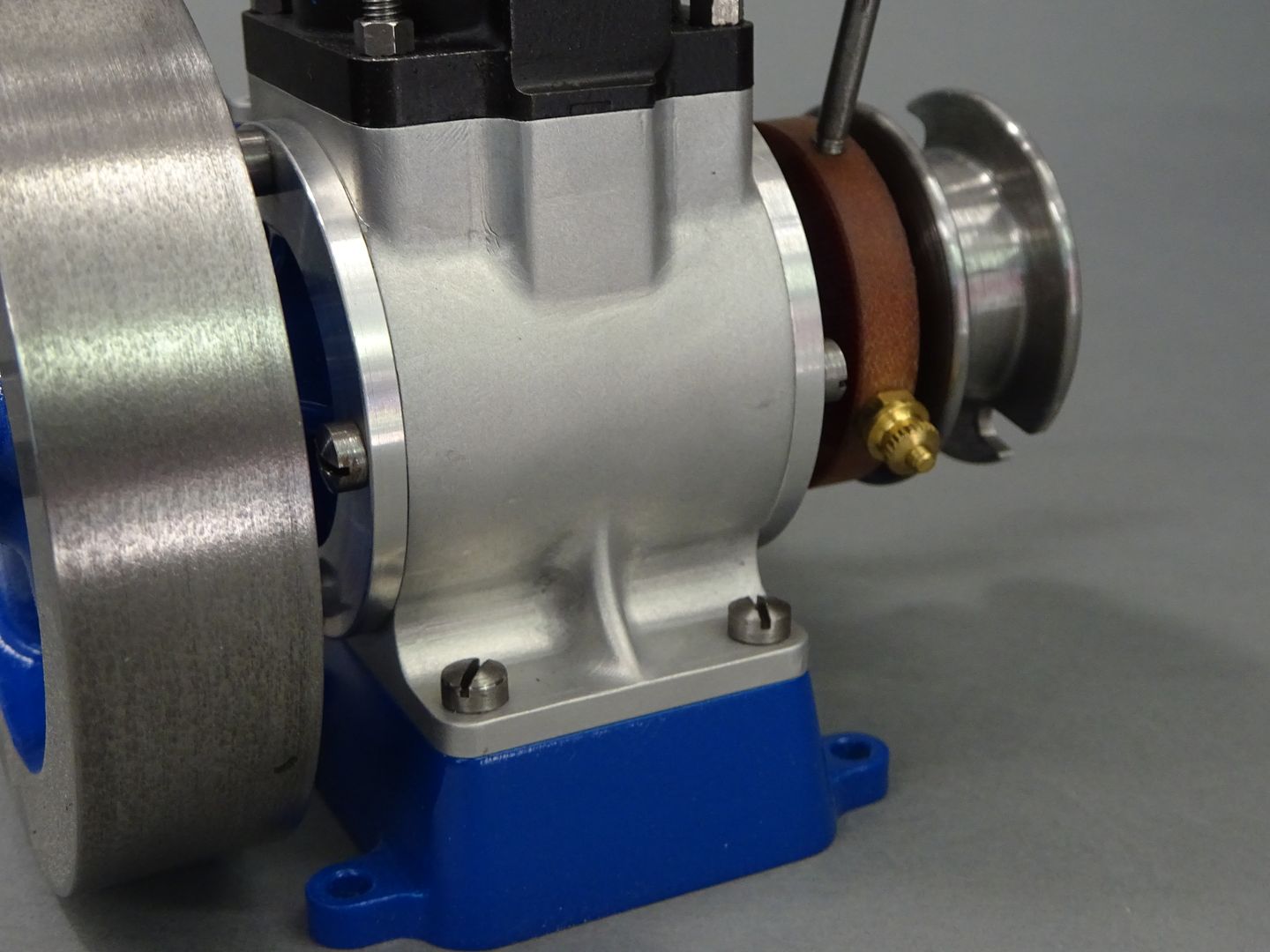
                                A group shot of progress at this stage. There is also a Tufnol disc which clamps around the end of the exposed main bearing and that carries one of the ignition contacts, rotating the disc advances or retards the timing.

                                #597338
                                JasonB
                                Moderator
                                  @jasonb

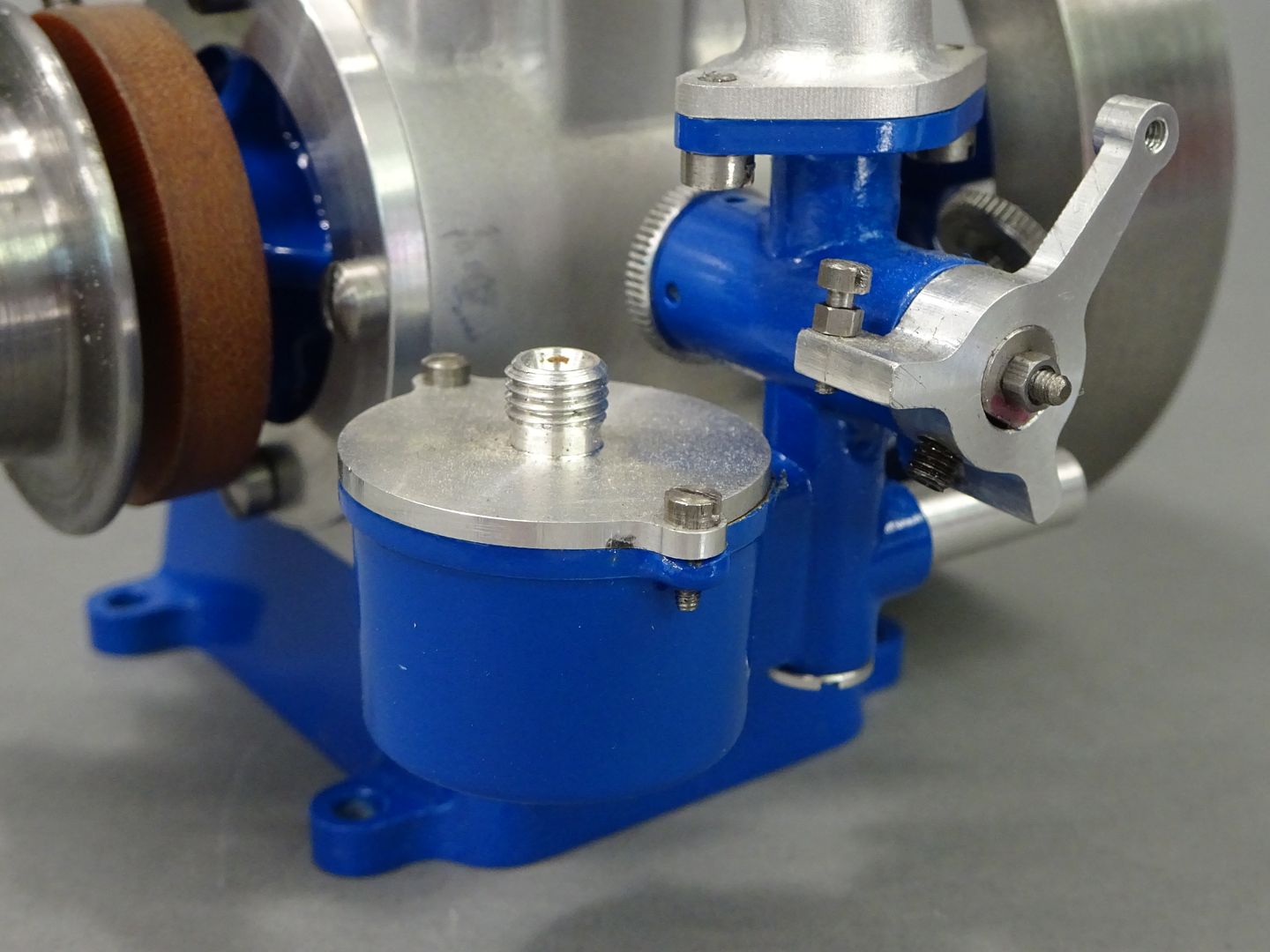
                                  The carb design for this engine is quite similar to that of the Stuart Lightweight I made some time ago and I took the same approach of silver soldering a bunch of brass parts together to replicate the casting all done on the manual machines. I did however make use of the CNC to shape the fuel bulb, first roughing it out with an adaptive cut – the inside has a shallow draft angle.

                                  And then a finishing path to tidy things up

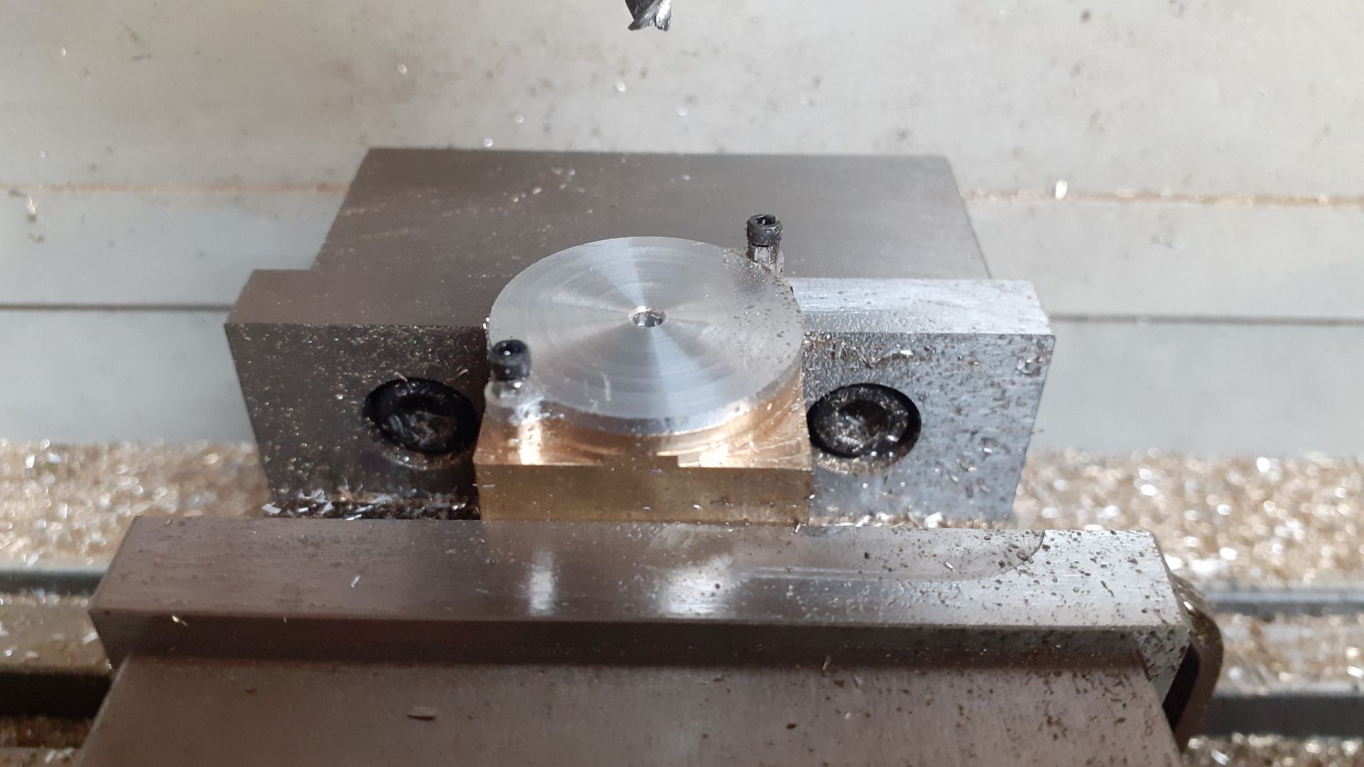
                                  While still in the vice the two lugs were drilled and tapped M1.6 and then used to hold the previously turned cover which was nounted upsid edown so as not to crash the cutter into it's threaded spigot. Again a roughing and then a finishing pass were used.

                                  Here are all the parts prior to soldering the body together

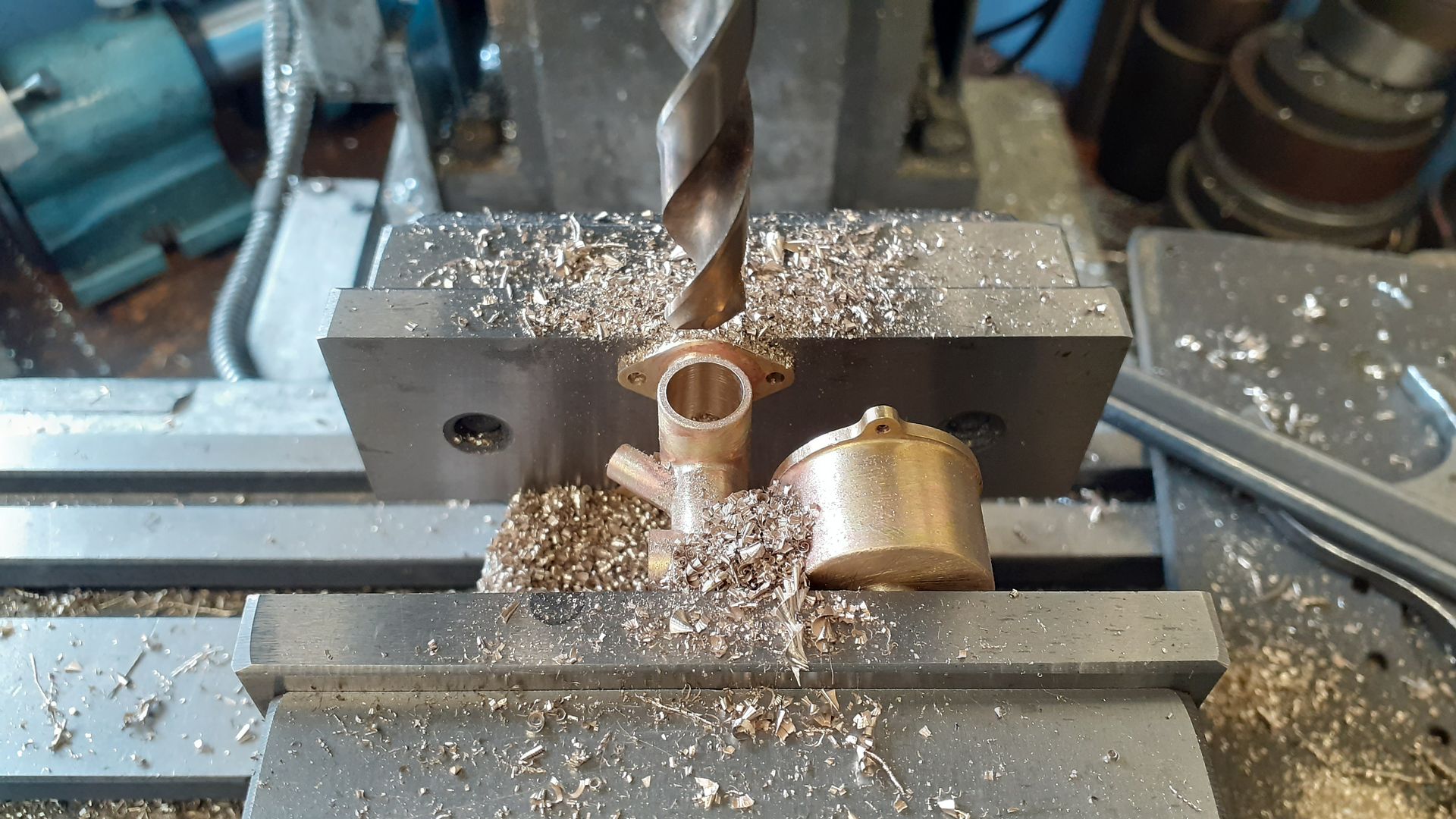
                                  Once soldered the body could be treated much like a casting and the various remaining hole sand passages added, here the throttle body is being drilled prior to reaming.

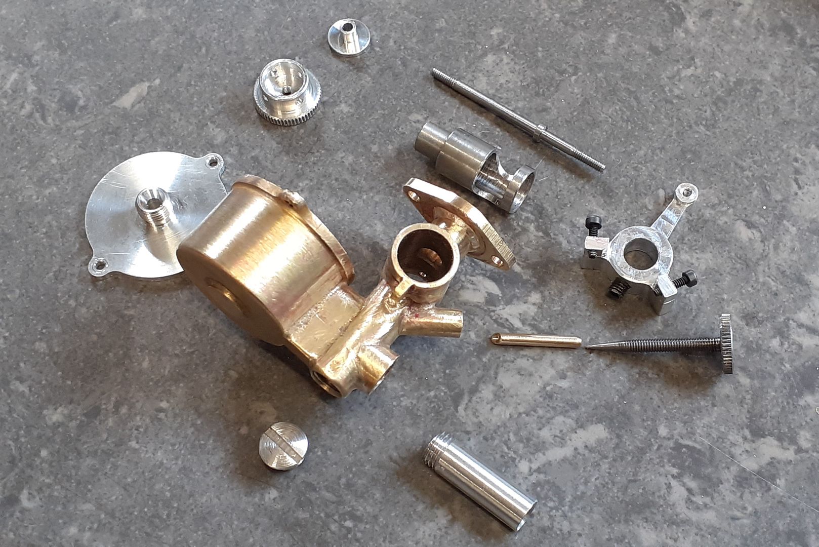
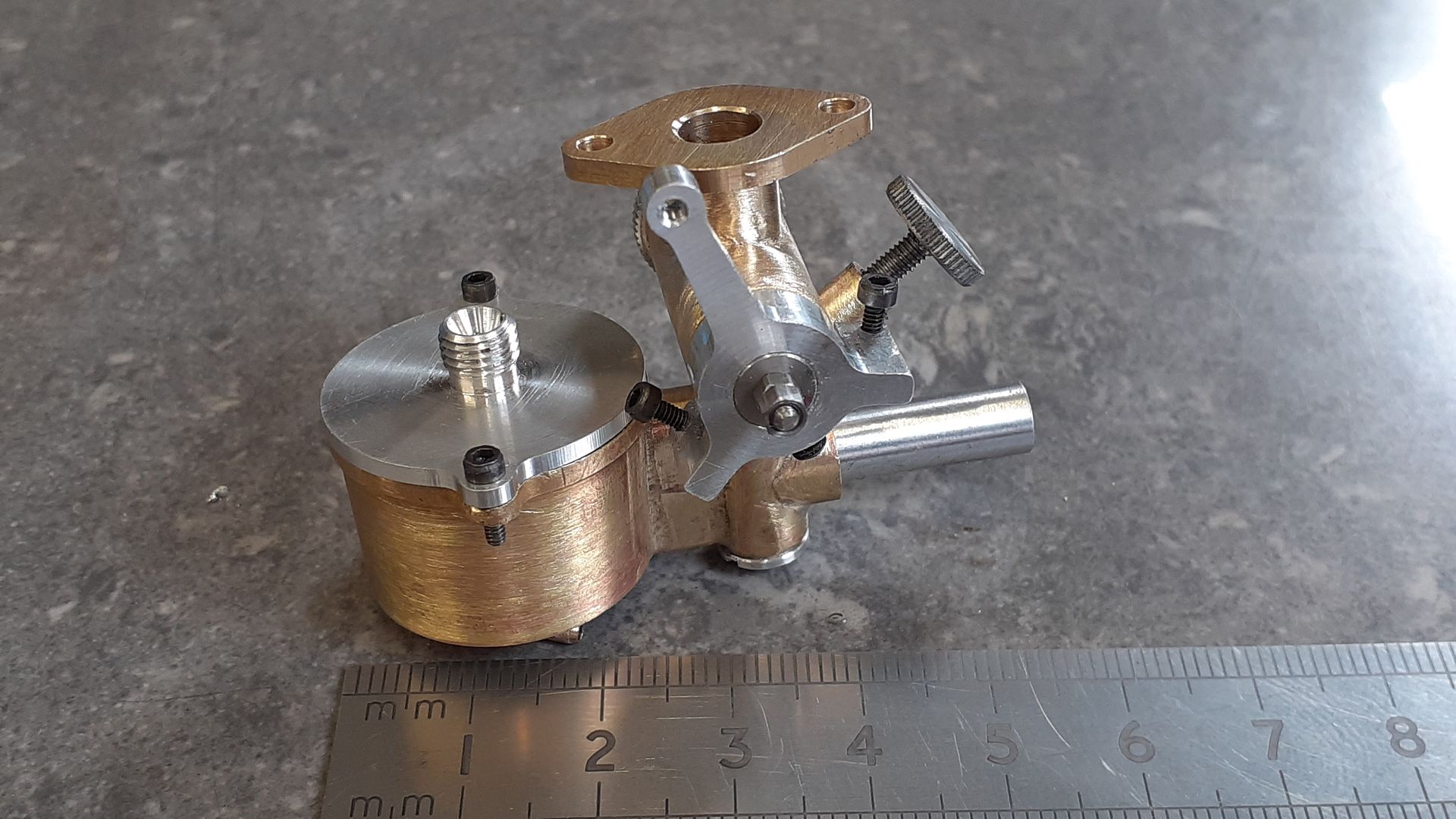
                                  And the completed carb in bits and all assembled

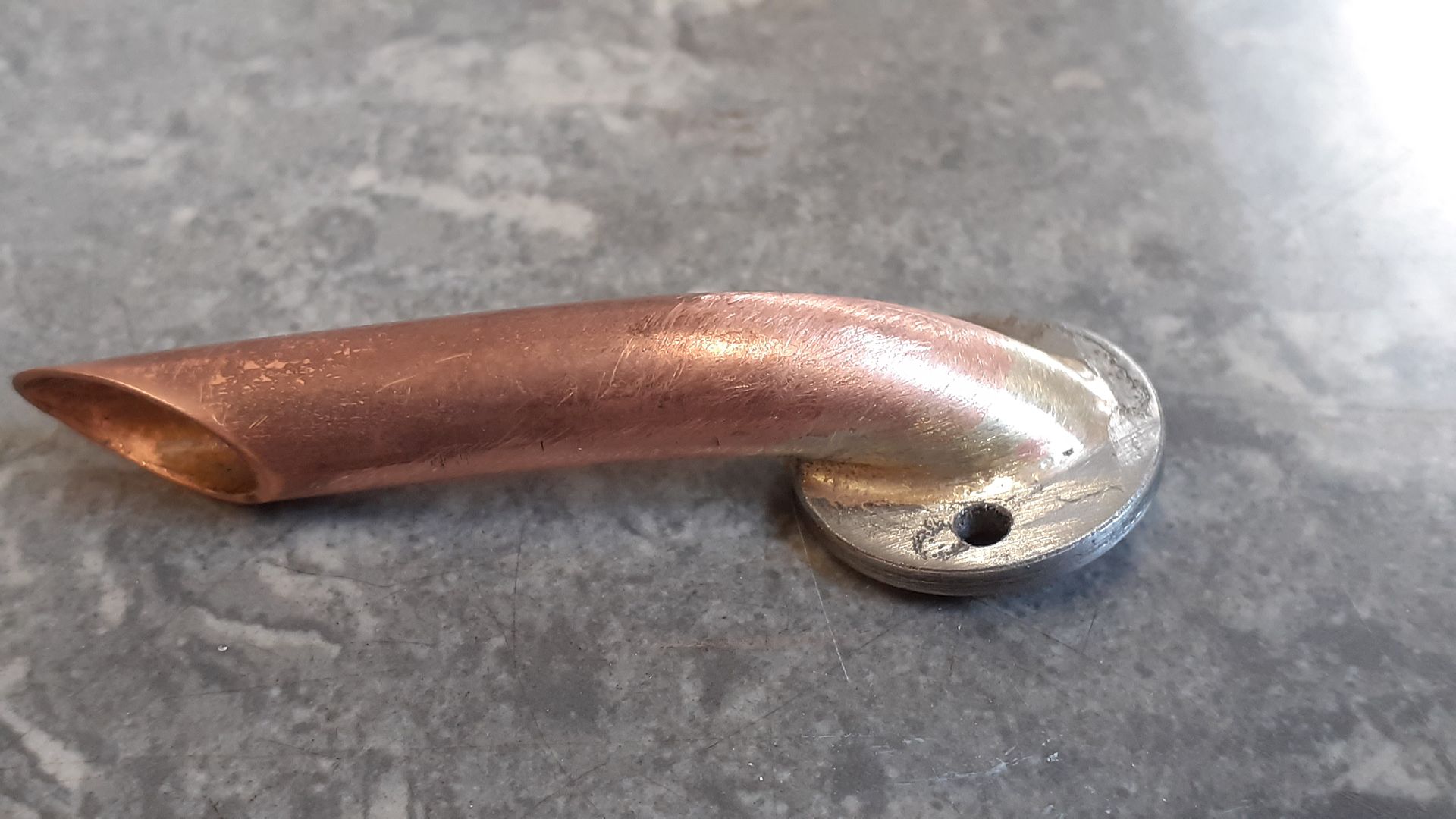
                                  I'm not one for silencers so a simple stub pipe exhaust was bent up from 8mm copper tube and silver soldered to the flange

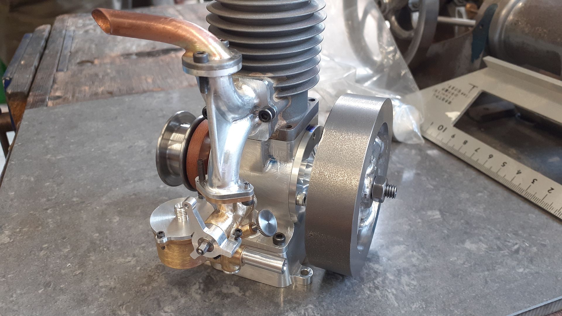
                                  Finally a quick trial fit on the manifold

                                  #597340
                                  David-Clark 1
                                  Participant
                                    @david-clark1

                                    Watching

                                    #597360
                                    DiogenesII
                                    Participant
                                      @diogenesii

                                      Likewise

                                      #598545
                                      JasonB
                                      Moderator
                                        @jasonb

                                        The conrod started out as a piece of round 2014 rod and was "squared up" on the manual mill using a facemill.

                                        I then narrowed down the big end using the same cutter before holding the rod on end to drill and tap for the big end fixings and then used a slitting saw to cut off the cap.

                                        I then drilled and reamed the two holes followed by milling away some of the waste so that the big end bolts could be fitted, I have them screwed in from the rod side not the cap side. Two top hat bushes were turned up so I could screw the rod to a piece of scrap and then mill to shape on the CNC.

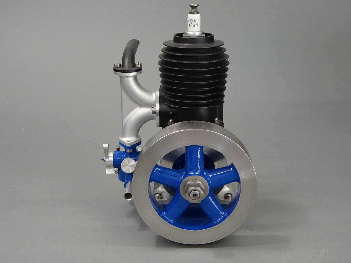
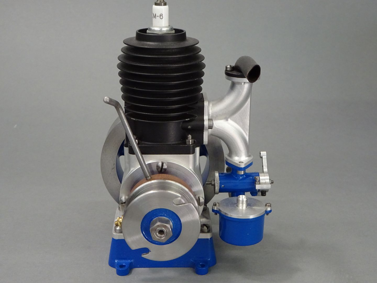
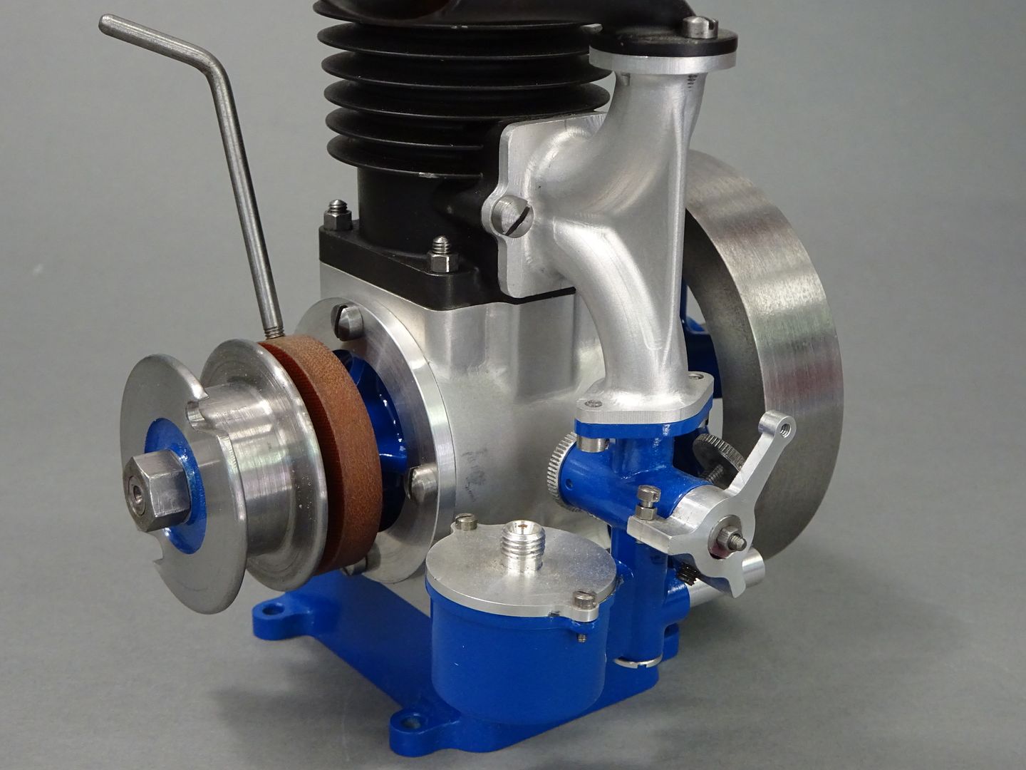
                                        Well that's about all the photos and video I took while making the engine. I finished it off with some Blue VHT and and black Thermacure paint with the crankcase and manifold left in the bear bead blasted finish.

                                        Well at this point you will all be expecting a video of the engine running but it is not obliging. I can't get a decent run out of it and by the time I have picked up the video it's already dead or dying. I know some say it's all about the journey which has been quite a fun one and I also learned a lot about the CNC but can't help feeling the journey is not really complete if you don't make it to the intended destination. Once the blisters from pulling the starter cord have healed I may have another go and make an adaptor to try a RC carb but more than likely it is destined to be eye candy on the shelf

                                        #598547
                                        derek hall 1
                                        Participant
                                          @derekhall1

                                          Fantastic work Jason – well done!

                                          What about using an electric starter, I am sure there are some still about that are (or were) used to start reluctant model ic glowplug and diesels…..

                                          Regards

                                          Derek

                                          #598548
                                          JasonB
                                          Moderator
                                            @jasonb

                                            I've had the cordless drill and my 12V RC starter on it but the pull cord still seems to be give the best results even though it is a pain to have to keep rewinding it.

                                            #598550
                                            MichaelR
                                            Participant
                                              @michaelr
                                              Posted by JasonB on 18/05/2022 18:10:40:

                                              I've had the cordless drill and my 12V RC starter on it but the pull cord still seems to be give the best results even though it is a pain to have to keep rewinding it.

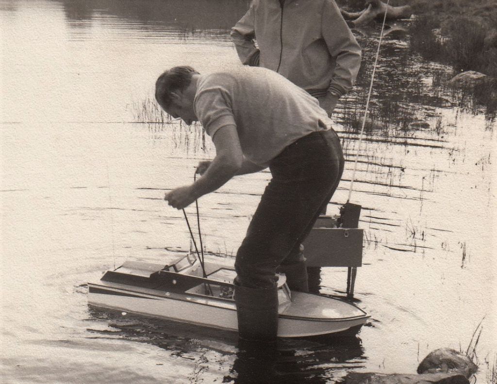
                                              Jason, In my model boating days I used a cross looped starting cord around the flywheel this method allowed you to spin the engine over without the need to rewind the starting cord, as you can see in my picture being above the the engine  when starting may not suit a bench mounted engine.

                                              The engine in my boat was a 15cc Gannet Petrol OHV

                                              Mike.Model Boat

                                              Edited By MichaelR on 18/05/2022 19:06:05

                                              Edited By MichaelR on 18/05/2022 19:11:25

                                              #598560
                                              DiogenesII
                                              Participant
                                                @diogenesii

                                                I was quite interested to see that there seems to be quite a lot of 'spare room' in the cases – 'specially given the amount of air that needs to get moving in the long inlet..

                                                ..this is a 'normal' three-port?

                                                ..it'd be interesting to hear the conclusions whatever the outcome is.. ..do you know if anyone else has one (to this design) running?

                                                Edited By DiogenesII on 18/05/2022 21:26:03

                                                #598571
                                                JasonB
                                                Moderator
                                                  @jasonb

                                                  Mike, I've seen that method used before but not tried it myself but will give it a go.

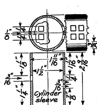
                                                  This shows the position of the ports on the original drawings. I've not been able to find any other examples of this engine, the only images are the poor ones from the original publication.

                                                  #598647
                                                  DiogenesII
                                                  Participant
                                                    @diogenesii

                                                    Thanks very much for that; it all kind of looks to be what (and where) you'd expect, hope you get a satisfactory run out of it soon..

                                                  Viewing 24 posts - 1 through 24 (of 24 total)
                                                  • Please log in to reply to this topic. Registering is free and easy using the links on the menu at the top of this page.

                                                  Advert

                                                  Latest Replies

                                                  Home Forums I/C Engines Topics

                                                  Viewing 25 topics - 1 through 25 (of 25 total)
                                                  Viewing 25 topics - 1 through 25 (of 25 total)

                                                  View full reply list.

                                                  Advert

                                                  Newsletter Sign-up